display DODGE DURANGO 2015 3.G User Guide
[x] Cancel search | Manufacturer: DODGE, Model Year: 2015, Model line: DURANGO, Model: DODGE DURANGO 2015 3.GPages: 236, PDF Size: 35.01 MB
Page 3 of 236
INTRODUCTION/WELCOME
WELCOME FROM FCA US LLC.......2
CONTROLS AT A GLANCE
DRIVER COCKPIT...............6INSTRUMENT CLUSTER...........8
GETTING STARTED
KEY FOB . . . . . . . . . . . . . . . . . . . 10REMOTE START . . . . . . . . . . . . . . . . 11KEYLESS ENTER-N-GO™.........12VEHICLE SECURITY ALARM........15SEAT BELT SYSTEMS............15SUPPLEMENTAL RESTRAINT SYSTEM(SRS) — AIR BAGS.............16CHILD RESTRAINTS............19HEAD RESTRAINTS.............25FRONT SEATS.................28REAR SEATS.................31HEATED/VENTILATED SEATS........34HEATED STEERING WHEEL........36TILT/TELESCOPING STEERINGCOLUMN...................37
OPERATING YOUR VEHICLE
ENGINE BREAK-INRECOMMENDATIONS............39TURN SIGNAL/WIPER/WASHER/HIGHBEAM LEVER.................40HEADLIGHT SWITCH............41ELECTRONIC SPEED CONTROL......42ADAPTIVE CRUISE CONTROL (ACC)....44FORWARD COLLISION WARNING (FCW)WITH MITIGATION..............49AUTOMATIC DIMMING MIRRORS.....51ELECTRONIC SHIFTER...........51AUTOSTICK..................52FUEL ECONOMY (ECO) MODE.......54AUTOMATIC CLIMATE CONTROLS.....55PA R K S E N S E®REAR PARK ASSIST.....60PA R K V I E W®REAR BACK-UP CAMERA...61BLIND SPOT MONITORING.........61POWER SUNROOF..............62WIND BUFFETING..............63
ELECTRONICSYOUR VEHICLE'S SOUND SYSTEM....64IDENTIFYING YOUR RADIO.........66Uconnect®ACCESS.............67Uconnect®5.0 . . . . . . . . . . . . . . . . 84Uconnect®8.4A...............96Uconnect®8.4AN.............124Uconnect®PHONE.............137STEERING WHEEL AUDIO CONTROLS...147DRIVER INFORMATION DISPLAY (DID)...148PROGRAMMABLE FEATURES.......150UNIVERSAL GARAGE DOOR OPENER(HomeLink®).................152
POWER INVERTER.............154POWER OUTLET..............155
OFF-ROAD CAPABILITIESALL-WHEEL DRIVE OPERATION.....157
UTILITYROOF LUGGAGE RACK..........160TRAILER TOWING WEIGHTS (MAXIMUMTRAILER WEIGHT RATINGS).......161RECREATIONAL TOWING (BEHINDMOTORHOME, ETC.)............163
WHAT TO DO IN EMERGENCIESROADSIDE ASSISTANCE..........168INSTRUMENT CLUSTER WARNINGLIGHTS....................168INSTRUMENT CLUSTER INDICATORLIGHTS...................173IF YOUR ENGINE OVERHEATS......175JACKING AND TIRE CHANGING.....176BATTERY LOCATION............186JUMP-STARTING..............186MANUAL PARK RELEASE.........189TOWING A DISABLED VEHICLE.....190FREEING A STUCK VEHICLE.......191EVENT DATA RECORDER (EDR).....192CAP-LESS FUEL FILL FUNNEL......192
MAINTAINING YOUR VEHICLE
OPENING THE HOOD...........193ENGINE COMPARTMENT.........194FLUID CAPACITIES.............198FLUIDS, LUBRICANTS AND GENUINEPA RT S....................199MAINTENANCE PROCEDURES......201MAINTENANCE SCHEDULE.......201MAINTENANCE RECORD.........205FUSES....................206TIRE PRESSURES.............209ADDING FUEL................210SPARE TIRES — IF EQUIPPED......211WHEEL AND WHEEL TRIM CARE....213REPLACEMENT BULBS..........214
CUSTOMER ASSISTANCE
FCA US LLC CUSTOMER CENTER....215CHRYSLER CANADA INC. CUSTOMERCENTER...................215ASSISTANCE FOR THE HEARINGIMPAIRED..................215PUBLICATIONS ORDERING........216REPORTING SAFETY DEFECTS IN THEUNITED STATES..............216
MOPAR® ACCESSORIESAUTHENTIC ACCESSORIES BY MOPAR®...217
FREQUENTLY ASKED QUESTIONS
FREQUENTLY ASKED QUESTIONS....218
INDEX.....................220
TABLE OF CONTENTS
Page 8 of 236
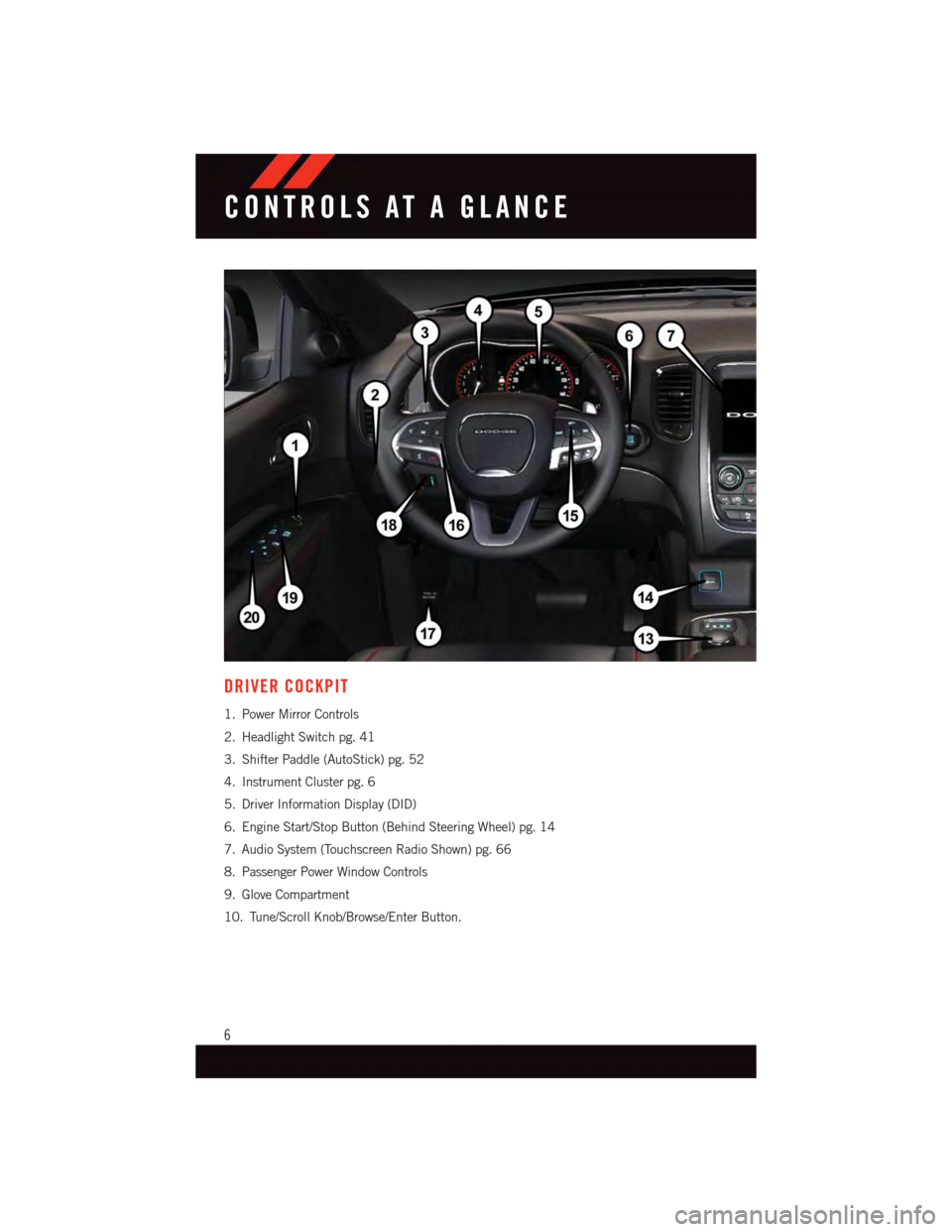
DRIVER COCKPIT
1. Power Mirror Controls
2. Headlight Switch pg. 41
3. Shifter Paddle (AutoStick) pg. 52
4. Instrument Cluster pg. 6
5. Driver Information Display (DID)
6. Engine Start/Stop Button (Behind Steering Wheel) pg. 14
7. Audio System (Touchscreen Radio Shown) pg. 66
8. Passenger Power Window Controls
9. Glove Compartment
10. Tune/Scroll Knob/Browse/Enter Button.
CONTROLS AT A GLANCE
6
Page 9 of 236
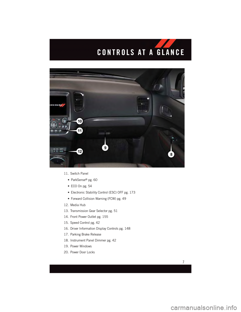
11. Switch Panel
•ParkSense®pg. 60
•ECOOnpg.54
•ElectronicStabilityControl(ESC)OFFpg.173
•ForwardCollisionWarning(FCW)pg.49
12. Media Hub
13. Transmission Gear Selector pg. 51
14. Front Power Outlet pg. 155
15. Speed Control pg. 42
16. Driver Information Display Controls pg. 148
17. Parking Brake Release
18. Instrument Panel Dimmer pg. 42
19. Power Windows
20. Power Door Locks
CONTROLS AT A GLANCE
7
Page 17 of 236
VEHICLE SECURITY ALARM
The Vehicle Security Alarm monitors the vehicle doors for unauthorized entry and the
Keyless Enter-N-Go™ START/STOP button for unauthorized operation. While the Vehicle
Security Alarm is armed, interior switches for door locks and decklid release are disabled.
If something triggers the alarm, the Vehicle Security Alarm will provide the following
audible and visible signals: the horn will pulse, the park lamps and/or turn signals will
flash, and the Vehicle Security Light in the instrument cluster will flash.
To Arm
Cycle the Keyless Enter-N-Go™ START/STOP button until the button display indicates
that the vehicle ignition is “OFF.” Push the power door lock switch while the door is open,
push the Key Fob LOCK button, or with one of the Key Fobs located outside the vehicle
and within 5 ft (1.5 m) of the driver's and passenger front door handles, push the Keyless
Enter-N-Go™ LOCK button located on the door handle.
NOTE:
After pushing the Keyless Enter-N-Go™ LOCK button, you must wait two seconds before
you can lock or unlock the vehicle via the door handle.
To Disarm
Push the Key Fob UNLOCK button or with one of the Key Fobs located outside the vehicle
and within 5 ft (1.5 m) of the driver's and passenger front door handles. Grab the Keyless
Enter-N-Go™ door handle and enter the vehicle, then push the Keyless Enter-N-Go™
START/STOP button (requires at least one valid Key Fob in the vehicle).
SEAT BELT SYSTEMS
Lap/Shoulder Belts
•Allseatingpositionsinyourvehicleareequippedwithlap/shoulderbelts.
•Besureeveryoneinyourvehicleisinaseatandusingaseatbeltproperly.
•Positionthelapbeltsothatitissnugandlieslowacrossyourhips,belowyour
abdomen. To remove slack in the lap belt portion, pull up on the shoulder belt. To loosen
the lap belt if it is too tight, tilt the latch plate and pull on the lap belt. A snug seat belt
reduces the risk of sliding under the seat belt in a collision.
•Positiontheshoulderbeltacrosstheshoulderandchestwithminimal,ifanyslackso
that it is comfortable and not resting on your neck. The retractor will withdraw any slack
in the shoulder belt.
Seat Belt Pretensioner
•Thefrontseatbeltsystemisequippedwithpretensioningdevicesthataredesignedto
remove slack from the seat belt in the event of a collision.
•Adeployedpretensioneroradeployedairbagmustbereplacedimmediately.
GETTING STARTED
15
Page 24 of 236
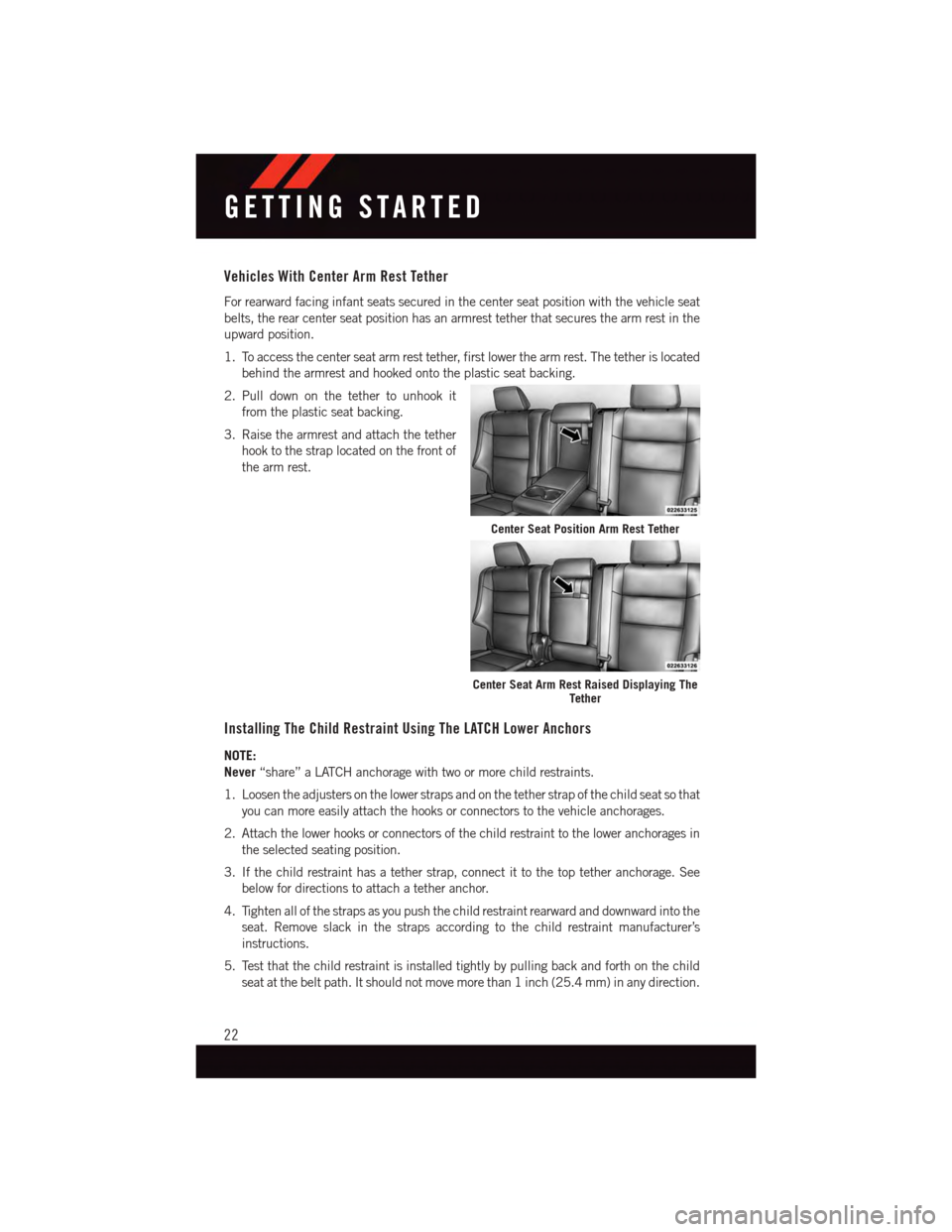
Vehicles With Center Arm Rest Tether
For rearward facing infant seats secured in the center seat position with the vehicle seat
belts, the rear center seat position has an armrest tether that secures the arm rest in the
upward position.
1. To access the center seat arm rest tether, first lower the arm rest. The tether is located
behind the armrest and hooked onto the plastic seat backing.
2. Pull down on the tether to unhook it
from the plastic seat backing.
3. Raise the armrest and attach the tether
hook to the strap located on the front of
the arm rest.
Installing The Child Restraint Using The LATCH Lower Anchors
NOTE:
Never“share” a LATCH anchorage with two or more child restraints.
1. Loosen the adjusters on the lower straps and on the tether strap of the child seat so that
you can more easily attach the hooks or connectors to the vehicle anchorages.
2. Attach the lower hooks or connectors of the child restraint to the lower anchorages in
the selected seating position.
3. If the child restraint has a tether strap, connect it to the top tether anchorage. See
below for directions to attach a tether anchor.
4. Tighten all of the straps as you push the child restraint rearward and downward into the
seat. Remove slack in the straps according to the child restraint manufacturer’s
instructions.
5. Test that the child restraint is installed tightly by pulling back and forth on the child
seat at the belt path. It should not move more than 1 inch (25.4 mm) in any direction.
Center Seat Position Arm Rest Tether
Center Seat Arm Rest Raised Displaying TheTether
GETTING STARTED
22
Page 29 of 236
Head Restraints — Rear Seats
The head restraints on the outboard seats are not adjustable. They automatically fold
forward when the rear seat is folded to a load floor position but do not return to their
normal position when the rear seat is raised. After returning either seat to its upright
position, raise the head restraint until it locks in place. The outboard head restraints are
not removable.
The center head restraint has limited adjustment. Lift upward on the head restraint to
raise it, or push downward on the head restraint to lower it.
WARNING!
Sitting in a seat with the head restraint in its lowered position could result in serious
injury or death in a collision. Always make sure the outboard head restraints are in their
upright positions when the seat is to be occupied.
NOTE:
For proper routing of a Child Seat Tether, refer to “Occupant Restraints” in “Things To
Know Before Starting” in your Owner’s Manual on the DVD for further information.
Power Folding Third Row Head Restraints
For improved visibility when in reverse, the third row head restraints can be folded using
the Uconnect®System.
Press the “Controls” button located on the bottom of the Uconnect®display.
Press the Headrest Fold buttonto power fold the third row head restraints.
NOTE:
•TheheadrestraintscanonlybefoldeddownwardusingtheHeadrestbutton.Thehead
restraints must be raised manually when occupying the third row.
•Donotfoldiftherearepassengersseatedinthethirdrowseats.
GETTING STARTED
27
Page 31 of 236
Memory Seat
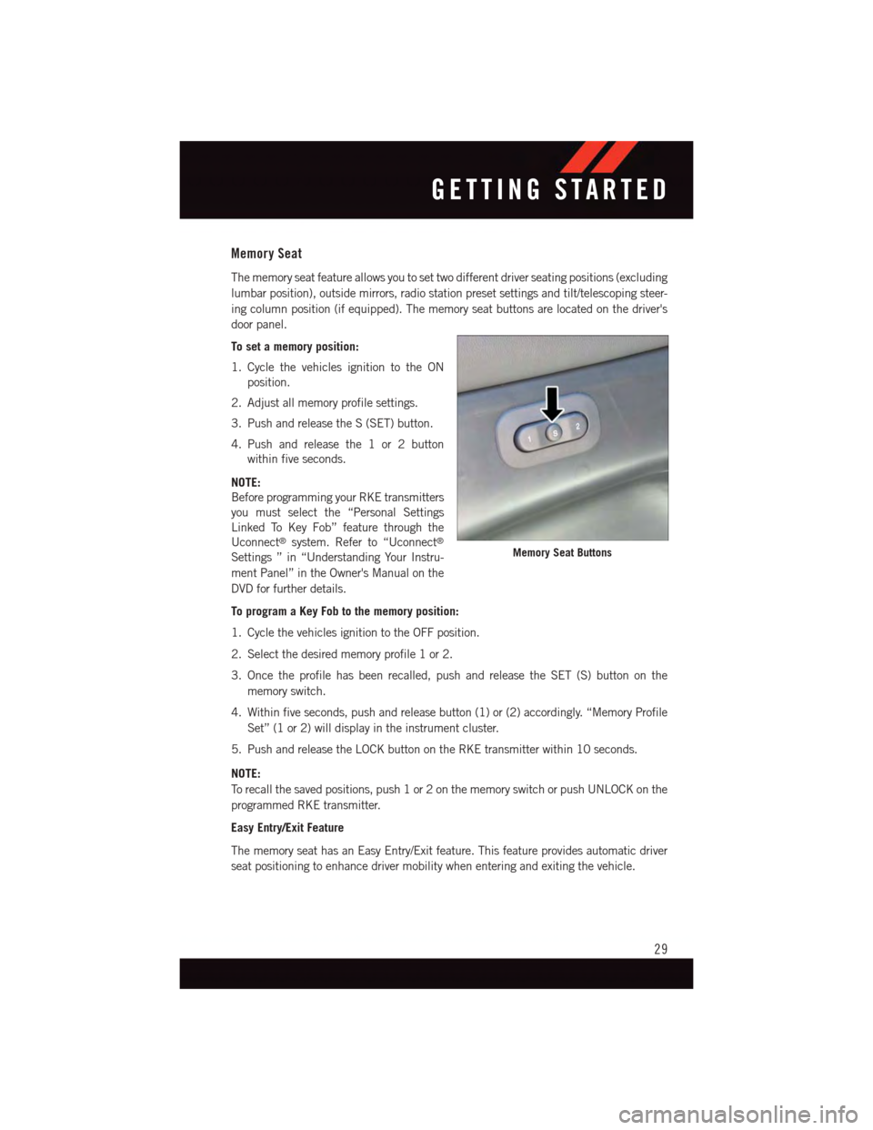
The memory seat feature allows you to set two different driver seating positions (excluding
lumbar position), outside mirrors, radio station preset settings and tilt/telescoping steer-
ing column position (if equipped). The memory seat buttons are located on the driver's
door panel.
To set a memory position:
1. Cycle the vehicles ignition to the ON
position.
2. Adjust all memory profile settings.
3. Push and release the S (SET) button.
4. Push and release the 1 or 2 button
within five seconds.
NOTE:
Before programming your RKE transmitters
you must select the “Personal Settings
Linked To Key Fob” feature through the
Uconnect®system. Refer to “Uconnect®
Settings ” in “Understanding Your Instru-
ment Panel” in the Owner's Manual on the
DVD for further details.
To program a Key Fob to the memory position:
1. Cycle the vehicles ignition to the OFF position.
2. Select the desired memory profile 1 or 2.
3. Once the profile has been recalled, push and release the SET (S) button on the
memory switch.
4. Within five seconds, push and release button (1) or (2) accordingly. “Memory Profile
Set” (1 or 2) will display in the instrument cluster.
5. Push and release the LOCK button on the RKE transmitter within 10 seconds.
NOTE:
To r e c a l l t h e s a v e d p o s i t i o n s , p u s h 1 o r 2 o n t h e m e m o r y s w i t c h o r p u s h U N L O C K o n t h e
programmed RKE transmitter.
Easy Entry/Exit Feature
The memory seat has an Easy Entry/Exit feature. This feature provides automatic driver
seat positioning to enhance driver mobility when entering and exiting the vehicle.
Memory Seat Buttons
GETTING STARTED
29
Page 36 of 236
HEATED/VENTILATED SEATS
Heated Seats
On some models, the front and rear seats may be equipped with heaters in both the seat
cushions and seatbacks.
The front driver and passenger heated seats are operated using the Uconnect®System.
WARNING!
•Personswhoareunabletofeelpaintotheskinbecauseofadvancedage,chronic
illness, diabetes, spinal cord injury, medication, alcohol use, exhaustion or other
physical condition must exercise care when using the seat heater. It may cause
burns even at low temperatures, especially if used for long periods of time.
•Donotplaceanythingontheseatorseatbackthatinsulatesagainstheat,suchas
ablanketorcushion.Thismaycausetheseatheatertooverheat.Sittinginaseat
that has been overheated could cause serious burns due to the increased surface
temperature of the seat.
Front Heated Seats
The front heated seats control buttons are located within the climate or controls screen of
the touchscreen.
Yo u c a n c h o o s e f r o m H I , L O o r O F F h e a t s e t t i n g s . T h e i n d i c a t o r l i g h t s i n e a c h s w i t c h
indicate the level of heat in use. Two indicator lights will illuminate for HI, one for LO and
none for OFF.
•Presstheheatedseatbuttononce to turn the HI setting ON.
•PresstheheatedseatbuttonasecondtimetoturntheLOsettingON.
•PresstheheatedseatbuttonathirdtimetoturntheheatingelementsOFF.
If the HI-level setting is selected, the system will automatically switch to LO-level after
approximately 60 minutes of continuous operation. At that time, the display will change
from HI to LO, indicating the change. The LO-level setting will turn OFF automatically
after approximately 45 minutes.
NOTE:
•Onceaheatsettingisselected,heatwillbefeltwithintwotofiveminutes.
•Theenginemustberunningfortheheatedseatstooperate.
Vehicles Equipped With Remote Start
On models that are equipped with remote start, the heated seats can be programed to
come on during a remote start.
This feature can be programmed through the Uconnect®system. Refer to “Uconnect®
Settings” in “Understanding Your Instrument Panel” in the Owner's Manual on the DVD.
GETTING STARTED
34
Page 44 of 236
Instrument Panel Dimmer
•Rotatethedimmercontroltotheextremebottompositiontofullydimtheinstrument
panel lights and prevent the interior lights from illuminating when a door is opened.
•Rotatethedimmercontroluptoincreasethebrightnessoftheinstrumentpanelwhen
the parking lights or headlights are on.
•Rotatethedimmercontroluptothenextdetentpositiontofullybrightentheodometer
and radio when the parking lights or headlights are on.
•Rotatethedimmercontroluptothelastdetentpositiontoturnontheinteriorlighting.
If your vehicle is equipped with a touchscreen, the dimming is programmable through the
Uconnect®system. Refer to “Uconnect®Settings ” in “Understanding Your Instrument
Panel” in the Owner's Manual on the DVD for further details.
ELECTRONIC SPEED CONTROL
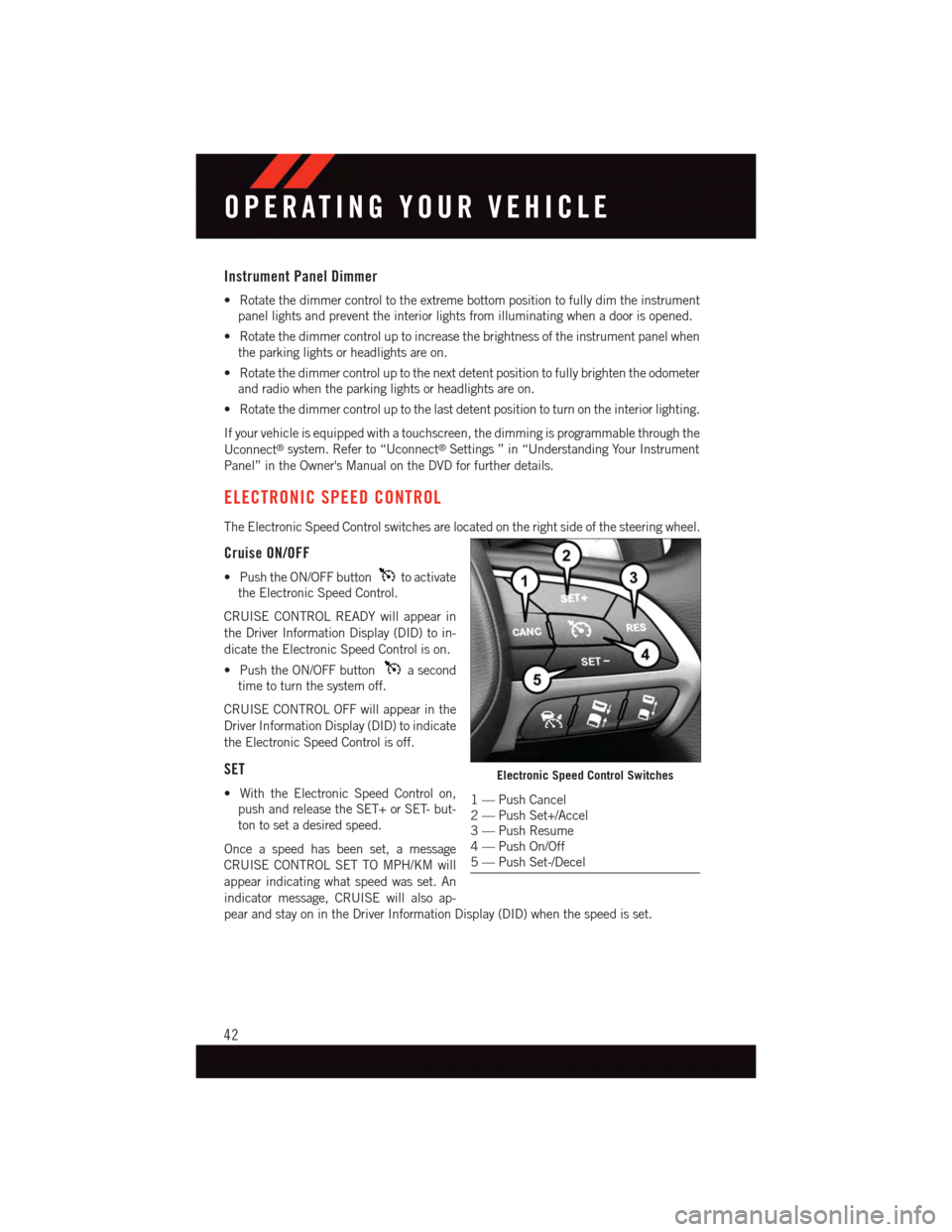
The Electronic Speed Control switches are located on the right side of the steering wheel.
Cruise ON/OFF
•PushtheON/OFFbuttonto activate
the Electronic Speed Control.
CRUISE CONTROL READY will appear in
the Driver Information Display (DID) to in-
dicate the Electronic Speed Control is on.
•PushtheON/OFFbuttonasecond
time to turn the system off.
CRUISE CONTROL OFF will appear in the
Driver Information Display (DID) to indicate
the Electronic Speed Control is off.
SET
•WiththeElectronicSpeedControlon,
push and release the SET+ or SET- but-
ton to set a desired speed.
Once a speed has been set, a message
CRUISE CONTROL SET TO MPH/KM will
appear indicating what speed was set. An
indicator message, CRUISE will also ap-
pear and stay on in the Driver Information Display (DID) when the speed is set.
Electronic Speed Control Switches
1—PushCancel2—PushSet+/Accel3—PushResume4—PushOn/Off5—PushSet-/Decel
OPERATING YOUR VEHICLE
42
Page 46 of 236
Resume
•Toresumeapreviouslyselectedsetspeedinmemory,pushtheRESbuttonand
release.
Cancel
•PushtheCANCELbutton,orapplythebrakestocancelthesetspeedandmaintainthe
set speed memory.
•PushtheON/OFFbuttontoturnthesystemoffanderasethesetspeedmemory.
WARNING!
Leaving the Electronic Speed Control system on when not in use is dangerous. You
could accidentally set the system or cause it to go faster than you want. You could lose
control and have an accident. Always leave the system OFF when you are not using it.
ADAPTIVE CRUISE CONTROL (ACC)
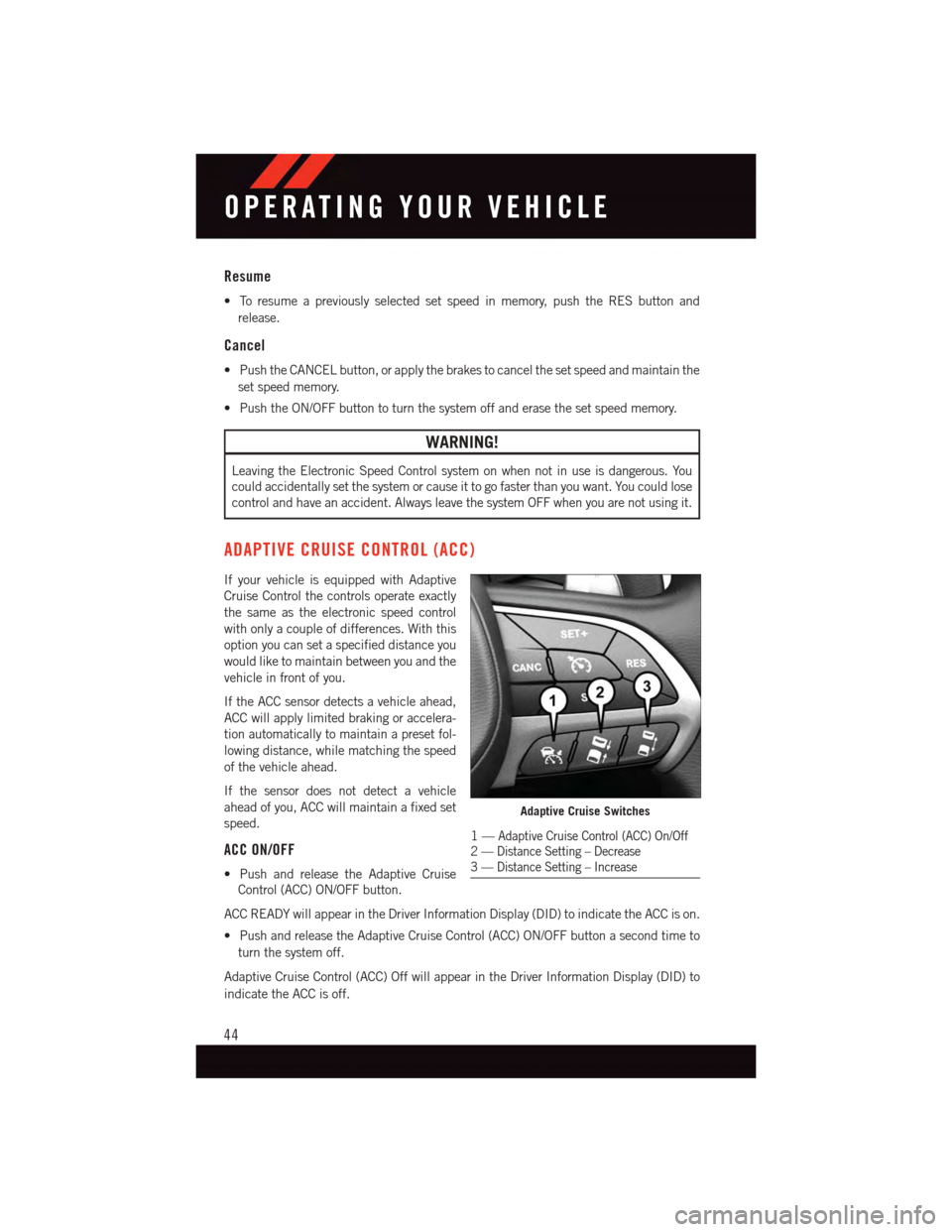
If your vehicle is equipped with Adaptive
Cruise Control the controls operate exactly
the same as the electronic speed control
with only a couple of differences. With this
option you can set a specified distance you
would like to maintain between you and the
vehicle in front of you.
If the ACC sensor detects a vehicle ahead,
ACC will apply limited braking or accelera-
tion automatically to maintain a preset fol-
lowing distance, while matching the speed
of the vehicle ahead.
If the sensor does not detect a vehicle
ahead of you, ACC will maintain a fixed set
speed.
ACC ON/OFF
•PushandreleasetheAdaptiveCruise
Control (ACC) ON/OFF button.
ACC READY will appear in the Driver Information Display (DID) to indicate the ACC is on.
•PushandreleasetheAdaptiveCruiseControl(ACC)ON/OFFbuttonasecondtimeto
turn the system off.
Adaptive Cruise Control (ACC) Off will appear in the Driver Information Display (DID) to
indicate the ACC is off.
Adaptive Cruise Switches
1—Adaptive Cruise Control (ACC) On/Off2—DistanceSetting–Decrease3—DistanceSetting–Increase
OPERATING YOUR VEHICLE
44