fuse DODGE DURANGO 2015 3.G User Guide
[x] Cancel search | Manufacturer: DODGE, Model Year: 2015, Model line: DURANGO, Model: DODGE DURANGO 2015 3.GPages: 236, PDF Size: 35.01 MB
Page 3 of 236
INTRODUCTION/WELCOME
WELCOME FROM FCA US LLC.......2
CONTROLS AT A GLANCE
DRIVER COCKPIT...............6INSTRUMENT CLUSTER...........8
GETTING STARTED
KEY FOB . . . . . . . . . . . . . . . . . . . 10REMOTE START . . . . . . . . . . . . . . . . 11KEYLESS ENTER-N-GO™.........12VEHICLE SECURITY ALARM........15SEAT BELT SYSTEMS............15SUPPLEMENTAL RESTRAINT SYSTEM(SRS) — AIR BAGS.............16CHILD RESTRAINTS............19HEAD RESTRAINTS.............25FRONT SEATS.................28REAR SEATS.................31HEATED/VENTILATED SEATS........34HEATED STEERING WHEEL........36TILT/TELESCOPING STEERINGCOLUMN...................37
OPERATING YOUR VEHICLE
ENGINE BREAK-INRECOMMENDATIONS............39TURN SIGNAL/WIPER/WASHER/HIGHBEAM LEVER.................40HEADLIGHT SWITCH............41ELECTRONIC SPEED CONTROL......42ADAPTIVE CRUISE CONTROL (ACC)....44FORWARD COLLISION WARNING (FCW)WITH MITIGATION..............49AUTOMATIC DIMMING MIRRORS.....51ELECTRONIC SHIFTER...........51AUTOSTICK..................52FUEL ECONOMY (ECO) MODE.......54AUTOMATIC CLIMATE CONTROLS.....55PA R K S E N S E®REAR PARK ASSIST.....60PA R K V I E W®REAR BACK-UP CAMERA...61BLIND SPOT MONITORING.........61POWER SUNROOF..............62WIND BUFFETING..............63
ELECTRONICSYOUR VEHICLE'S SOUND SYSTEM....64IDENTIFYING YOUR RADIO.........66Uconnect®ACCESS.............67Uconnect®5.0 . . . . . . . . . . . . . . . . 84Uconnect®8.4A...............96Uconnect®8.4AN.............124Uconnect®PHONE.............137STEERING WHEEL AUDIO CONTROLS...147DRIVER INFORMATION DISPLAY (DID)...148PROGRAMMABLE FEATURES.......150UNIVERSAL GARAGE DOOR OPENER(HomeLink®).................152
POWER INVERTER.............154POWER OUTLET..............155
OFF-ROAD CAPABILITIESALL-WHEEL DRIVE OPERATION.....157
UTILITYROOF LUGGAGE RACK..........160TRAILER TOWING WEIGHTS (MAXIMUMTRAILER WEIGHT RATINGS).......161RECREATIONAL TOWING (BEHINDMOTORHOME, ETC.)............163
WHAT TO DO IN EMERGENCIESROADSIDE ASSISTANCE..........168INSTRUMENT CLUSTER WARNINGLIGHTS....................168INSTRUMENT CLUSTER INDICATORLIGHTS...................173IF YOUR ENGINE OVERHEATS......175JACKING AND TIRE CHANGING.....176BATTERY LOCATION............186JUMP-STARTING..............186MANUAL PARK RELEASE.........189TOWING A DISABLED VEHICLE.....190FREEING A STUCK VEHICLE.......191EVENT DATA RECORDER (EDR).....192CAP-LESS FUEL FILL FUNNEL......192
MAINTAINING YOUR VEHICLE
OPENING THE HOOD...........193ENGINE COMPARTMENT.........194FLUID CAPACITIES.............198FLUIDS, LUBRICANTS AND GENUINEPA RT S....................199MAINTENANCE PROCEDURES......201MAINTENANCE SCHEDULE.......201MAINTENANCE RECORD.........205FUSES....................206TIRE PRESSURES.............209ADDING FUEL................210SPARE TIRES — IF EQUIPPED......211WHEEL AND WHEEL TRIM CARE....213REPLACEMENT BULBS..........214
CUSTOMER ASSISTANCE
FCA US LLC CUSTOMER CENTER....215CHRYSLER CANADA INC. CUSTOMERCENTER...................215ASSISTANCE FOR THE HEARINGIMPAIRED..................215PUBLICATIONS ORDERING........216REPORTING SAFETY DEFECTS IN THEUNITED STATES..............216
MOPAR® ACCESSORIESAUTHENTIC ACCESSORIES BY MOPAR®...217
FREQUENTLY ASKED QUESTIONS
FREQUENTLY ASKED QUESTIONS....218
INDEX.....................220
TABLE OF CONTENTS
Page 157 of 236

POWER OUTLET
The front power outlet is located in the front center storage bin of the instrument panel.
There is one power outlet located in the
center console.
The rear power outlet is located in the right
rear cargo area.
The power outlets are labeled with either a
“key” or a “battery” symbol to indicate how
the outlet is powered. Power outlets labeled
with a “key” are powered when the ignition
switch is in the ON/RUN or ACC position,
while the outlets labeled with a “battery”
are connected directly to the battery and
powered at all times.
NOTE:
•Donotexceedthemaximumpowerof
160 Watts (13 Amps) at 12 Volts. If the
160 Watt (13 Amp) power rating is ex-
ceeded, the fuse protecting the system
will need to be replaced. See below im-
age for fuse locations.
•Poweroutletsaredesignedforaccessory
plugs only. Do not insert any other object
in the power outlet as this will damage
the outlet and blow the fuse. Improper use of the power outlet can cause damage not
covered by your new vehicle warranty.
Front Power Outlet
Center Console Outlet
ELECTRONICS
155
Page 158 of 236
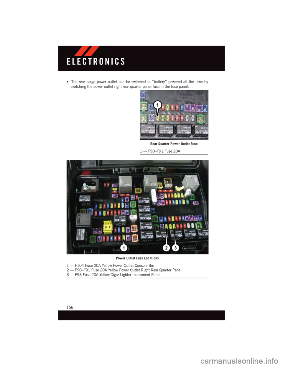
•Therearcargopoweroutletcanbeswitchedto“battery”poweredallthetimeby
switching the power outlet right rear quarter panel fuse in the fuse panel.
Rear Quarter Power Outlet Fuse
1—F90–F91Fuse20A
Power Outlet Fuse Locations
1—F104Fuse20AYellowPowerOutletConsoleBin2—F90–F91Fuse20AYellowPowerOutletRightRearQuarterPanel3—F93Fuse20AYellowCigarLighterInstrumentPanel
ELECTRONICS
156
Page 197 of 236
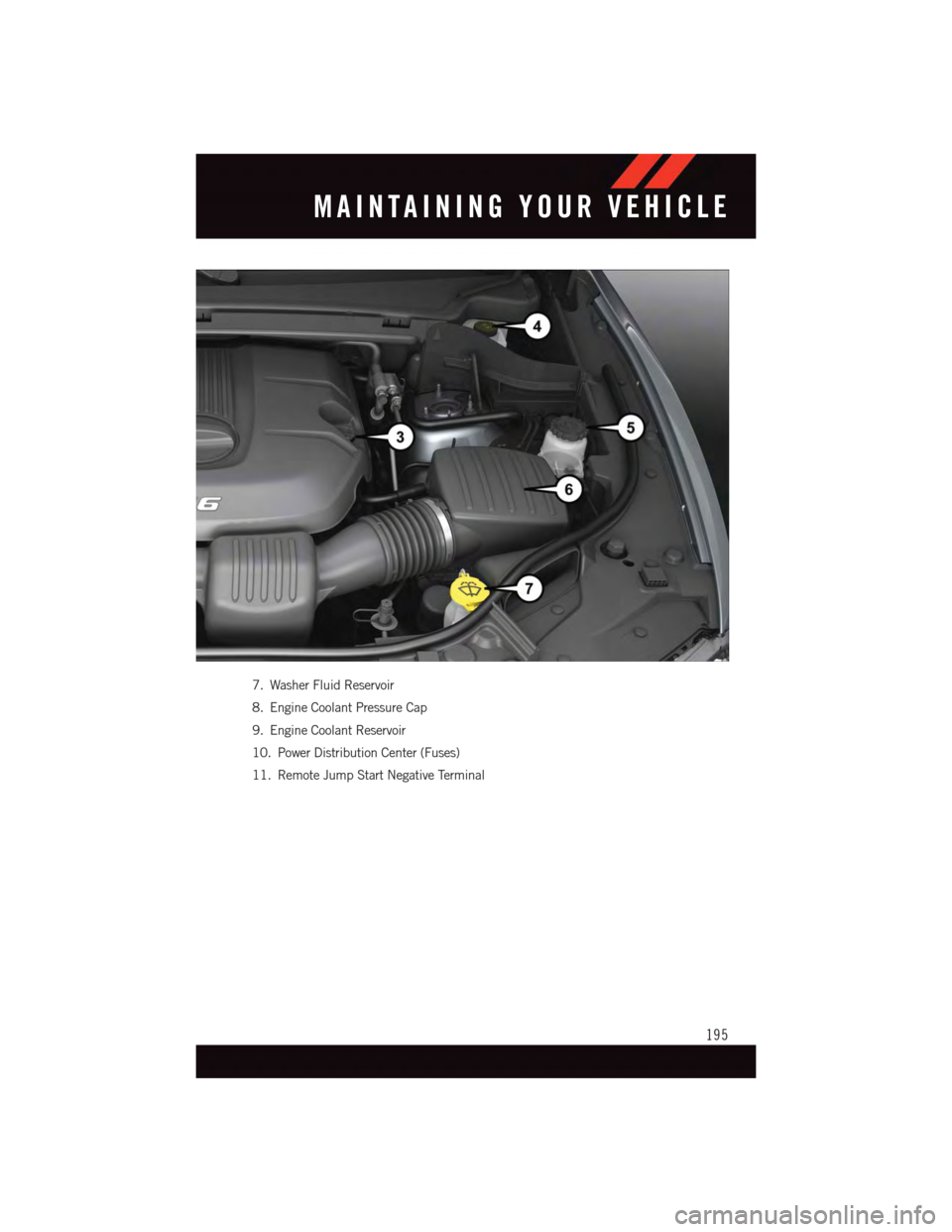
7. Washer Fluid Reservoir
8. Engine Coolant Pressure Cap
9. Engine Coolant Reservoir
10. Power Distribution Center (Fuses)
11. Remote Jump Start Negative Terminal
MAINTAINING YOUR VEHICLE
195
Page 199 of 236
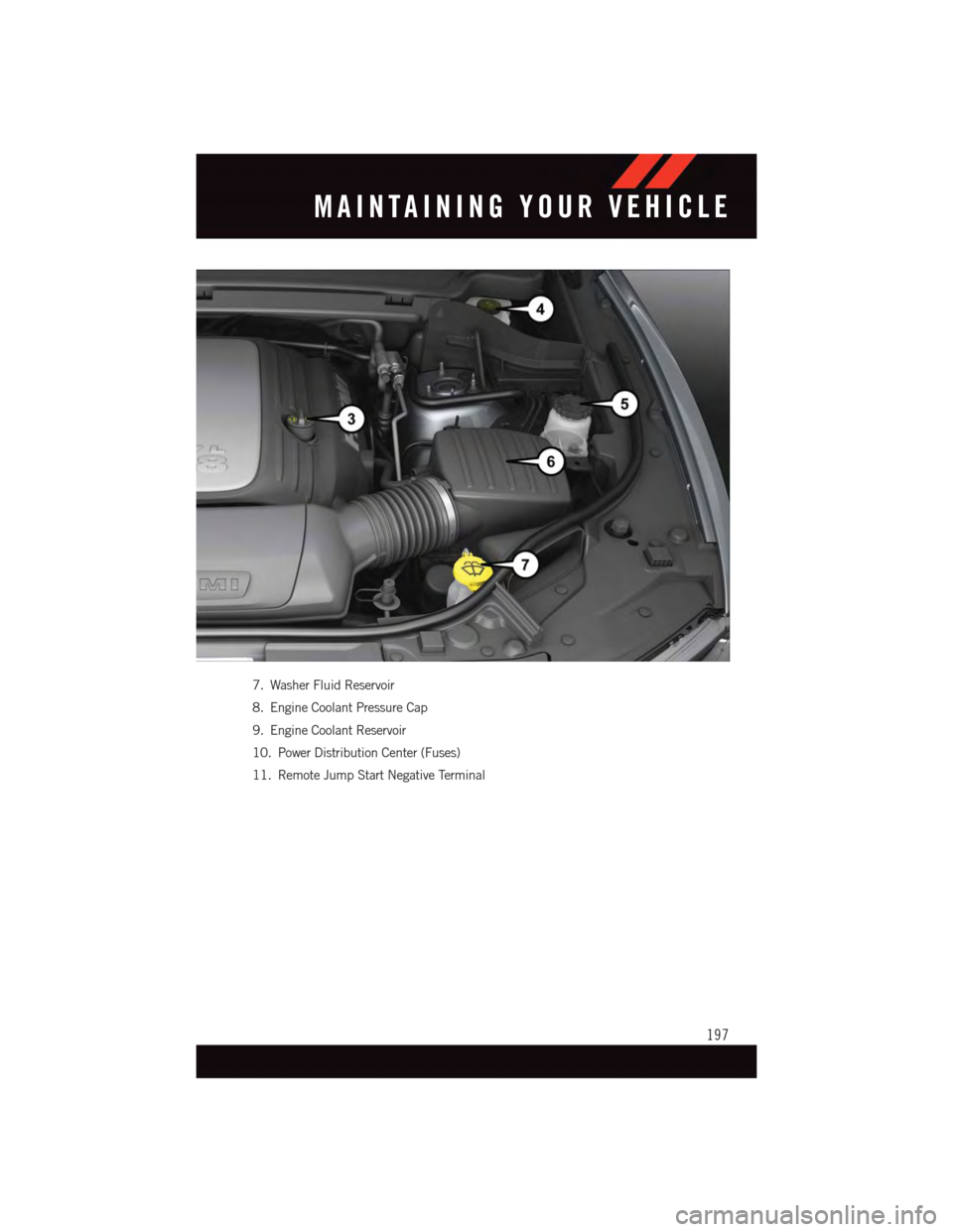
7. Washer Fluid Reservoir
8. Engine Coolant Pressure Cap
9. Engine Coolant Reservoir
10. Power Distribution Center (Fuses)
11. Remote Jump Start Negative Terminal
MAINTAINING YOUR VEHICLE
197
Page 208 of 236
FUSES
WARNING!
•Whenreplacingablownfuse,alwaysuseanappropriatereplacementfusewiththe
same amp rating as the original fuse. Never replace a fuse with another fuse of
higher amp rating. Never replace a blown fuse with metal wires or any other
material. Failure to use proper fuses may result in serious personal injury, fire and/or
property damage.
•Beforereplacingafuse,makesurethattheignitionisoffandthatalltheother
services are switched off and/or disengaged.
•Ifthereplacedfuseblowsagain,contactanauthorizeddealer.
•Ifageneralprotectionfuseforsafetysystems(airbagsystem,brakingsystem),
power unit systems (engine system, gearbox system) or steering system blows,
contact an authorized dealer.
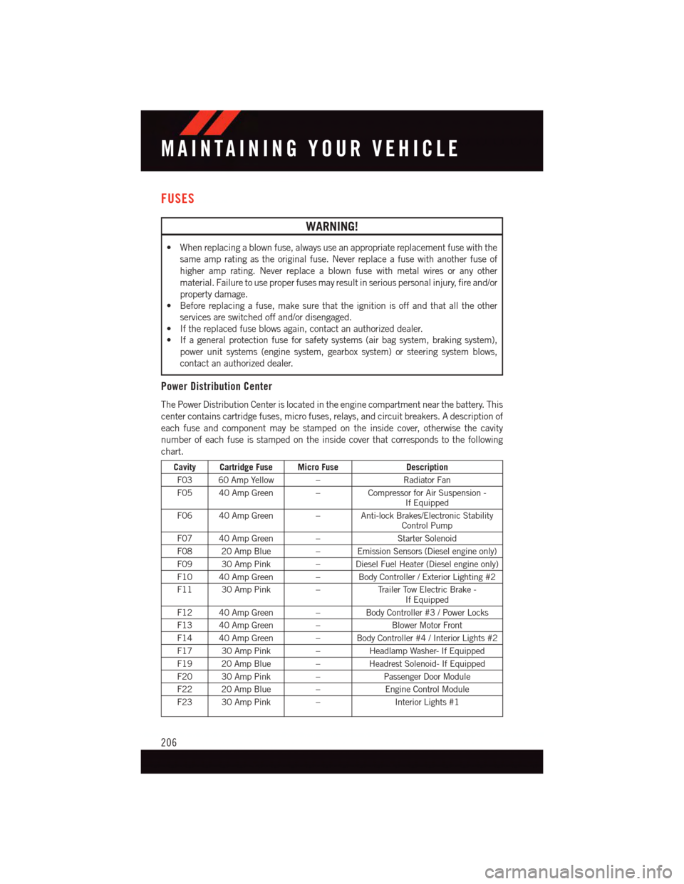
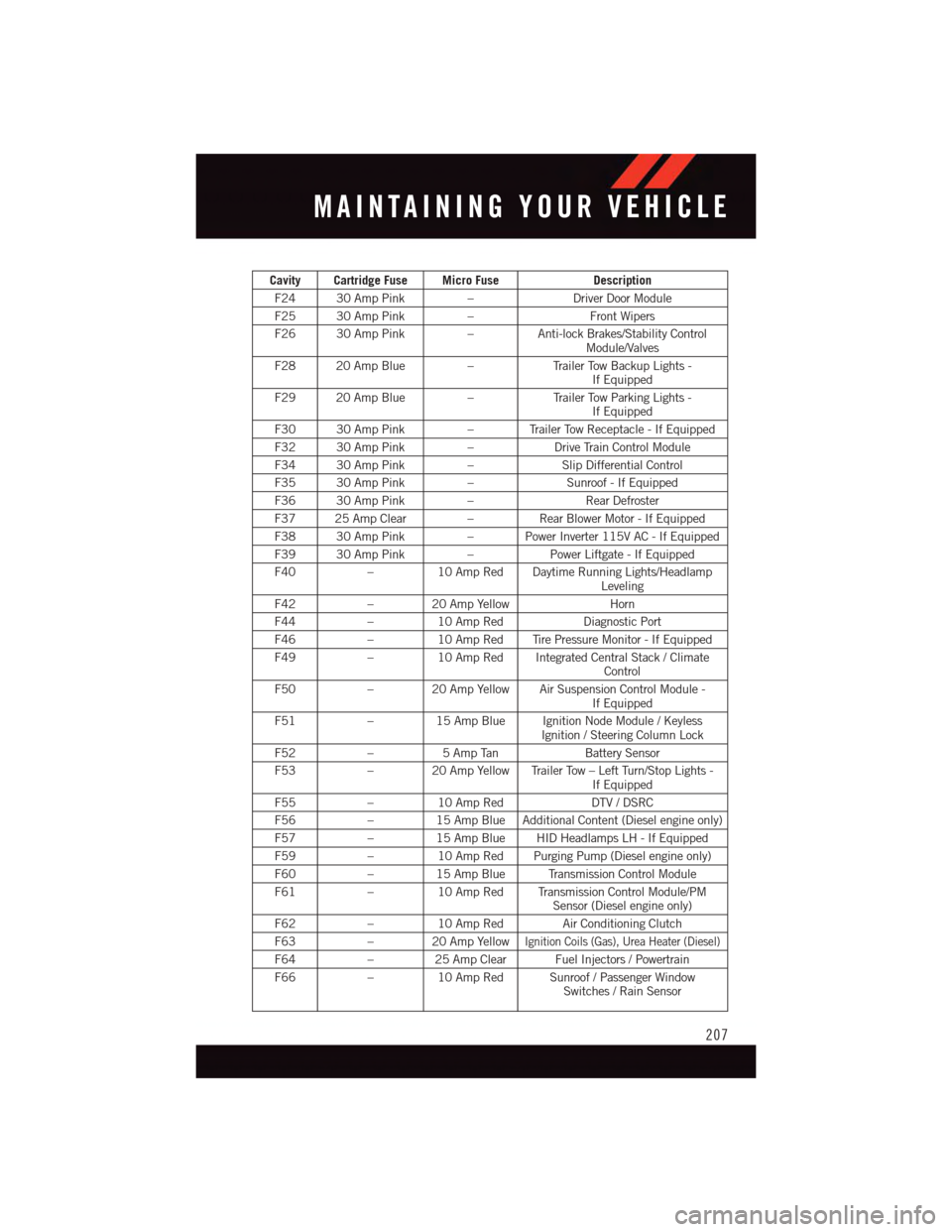
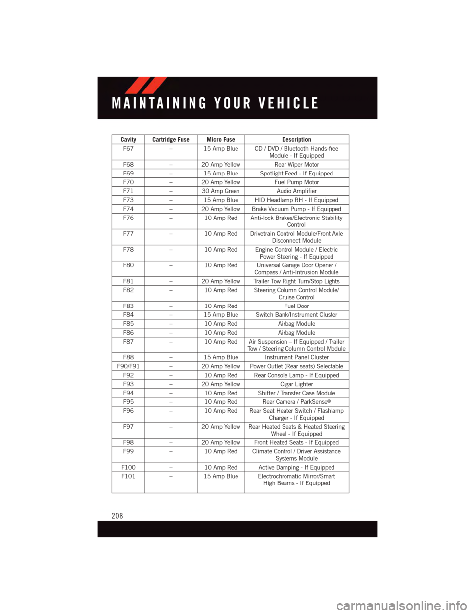
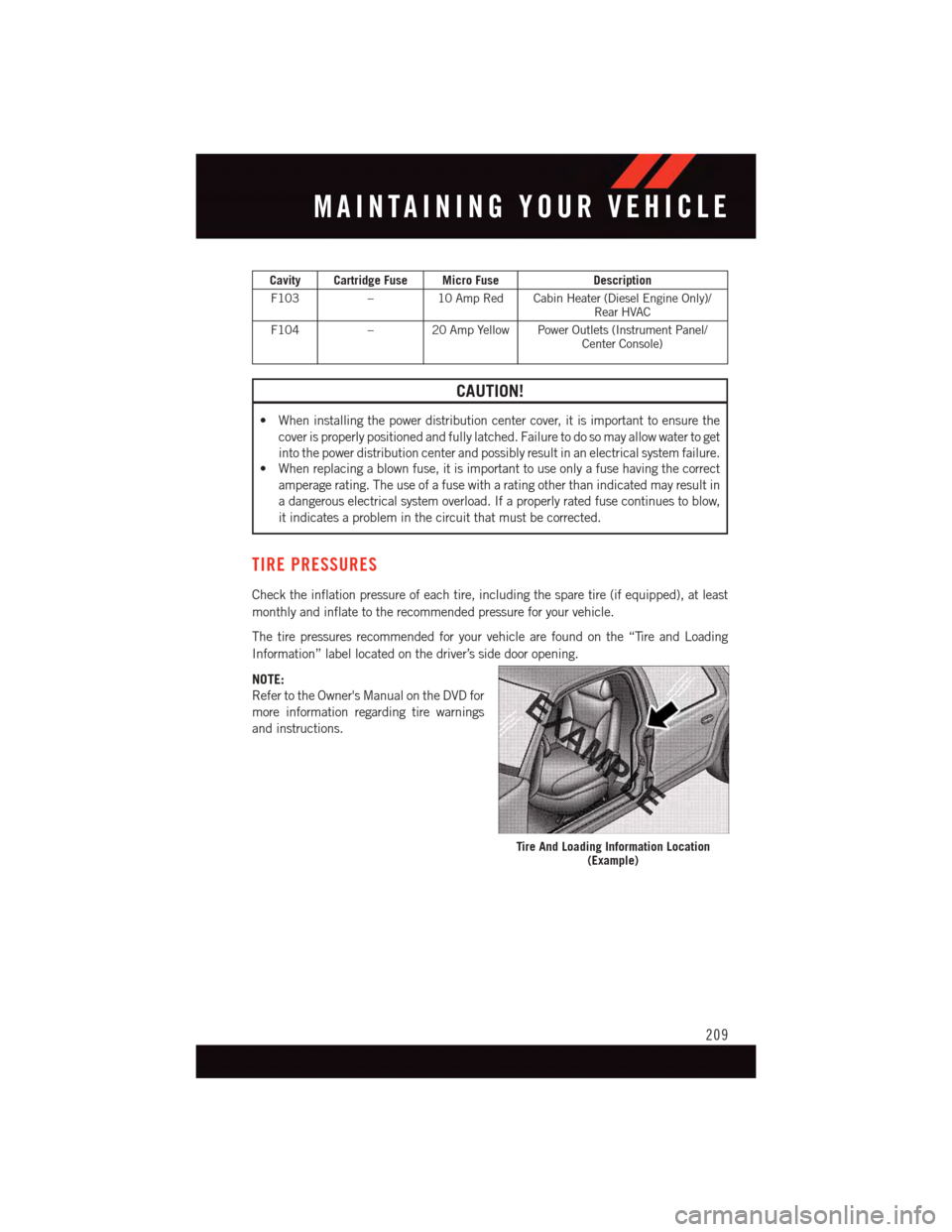
Power Distribution Center
The Power Distribution Center is located in the engine compartment near the battery. This
center contains cartridge fuses, micro fuses, relays, and circuit breakers. A description of
each fuse and component may be stamped on the inside cover, otherwise the cavity
number of each fuse is stamped on the inside cover that corresponds to the following
chart.
Cavity Cartridge Fuse Micro FuseDescription
F03 60 Amp Yellow –Radiator Fan
F05 40 Amp Green –Compressor for Air Suspension -If Equipped
F06 40 Amp Green – Anti-lock Brakes/Electronic StabilityControl Pump
F07 40 Amp Green –Starter Solenoid
F08 20 Amp Blue–EmissionSensors(Dieselengineonly)
F09 30 Amp Pink–DieselFuelHeater(Dieselengineonly)
F10 40 Amp Green – Body Controller / Exterior Lighting #2
F11 30 Amp Pink–Tr a i l e r To w E l e c t r i c B r a k e -If Equipped
F12 40 Amp Green –Body Controller #3 / Power Locks
F13 40 Amp Green –Blower Motor Front
F14 40 Amp Green – Body Controller #4 / Interior Lights #2
F17 30 Amp Pink–Headlamp Washer- If Equipped
F19 20 Amp Blue–Headrest Solenoid- If Equipped
F20 30 Amp Pink–Passenger Door Module
F22 20 Amp Blue–Engine Control Module
F23 30 Amp Pink–Interior Lights #1
MAINTAINING YOUR VEHICLE
206
Page 209 of 236
Cavity Cartridge Fuse Micro FuseDescription
F24 30 Amp Pink–Driver Door Module
F25 30 Amp Pink–Front Wipers
F26 30 Amp Pink–Anti-lock Brakes/Stability ControlModule/Valves
F28 20 Amp Blue–Tr a i l e r To w B a c k u p L i g h t s -If Equipped
F29 20 Amp Blue–Tr a i l e r To w P a r k i n g L i g h t s -If Equipped
F30 30 Amp Pink–TrailerTowReceptacle-IfEquipped
F32 30 Amp Pink–Drive Train Control Module
F34 30 Amp Pink–Slip Differential Control
F35 30 Amp Pink–Sunroof - If Equipped
F36 30 Amp Pink–Rear Defroster
F37 25 Amp Clear –Rear Blower Motor - If Equipped
F38 30 Amp Pink–PowerInverter115VAC-IfEquipped
F39 30 Amp Pink–Power Liftgate - If Equipped
F40–10 Amp Red Daytime Running Lights/HeadlampLeveling
F42–20AmpYellowHorn
F44–10 Amp RedDiagnostic Port
F46–10 Amp Red Tire Pressure Monitor - If Equipped
F49–10 Amp Red Integrated Central Stack / ClimateControl
F50–20AmpYellowAirSuspensionControlModule-If Equipped
F51–15 Amp Blue Ignition Node Module / KeylessIgnition / Steering Column Lock
F52–5AmpTanBattery Sensor
F53–20AmpYellowTrailerTow–LeftTurn/StopLights-If Equipped
F55–10 Amp RedDTV / DSRC
F56–15 Amp Blue Additional Content (Diesel engine only)
F57–15 Amp Blue HID Headlamps LH - If Equipped
F59–10 Amp Red Purging Pump (Diesel engine only)
F60–15 Amp Blue Transmission Control Module
F61–10 Amp Red Transmission Control Module/PMSensor (Diesel engine only)
F62–10 Amp Red Air Conditioning Clutch
F63–20AmpYellowIgnition Coils (Gas), Urea Heater (Diesel)
F64–25AmpClearFuelInjectors/Powertrain
F66–10 Amp Red Sunroof / Passenger WindowSwitches / Rain Sensor
MAINTAINING YOUR VEHICLE
207
Page 210 of 236
Cavity Cartridge Fuse Micro FuseDescription
F67–15 Amp Blue CD / DVD / Bluetooth Hands-freeModule - If Equipped
F68–20AmpYellowRear Wiper Motor
F69–15 Amp Blue Spotlight Feed - If Equipped
F70–20AmpYellowFuel Pump Motor
F71–30AmpGreenAudio Amplifier
F73–15 Amp Blue HID Headlamp RH - If Equipped
F74–20AmpYellowBrakeVacuumPump-IfEquipped
F76–10 Amp Red Anti-lock Brakes/Electronic StabilityControl
F77–10 Amp Red Drivetrain Control Module/Front AxleDisconnect Module
F78–10 Amp Red Engine Control Module / ElectricPower Steering - If Equipped
F80–10 Amp Red Universal Garage Door Opener /Compass / Anti-Intrusion Module
F81–20AmpYellowTrailerTowRightTurn/StopLights
F82–10 Amp Red Steering Column Control Module/Cruise Control
F83–10 Amp RedFuel Door
F84–15 Amp Blue Switch Bank/Instrument Cluster
F85–10 Amp RedAirbag Module
F86–10 Amp RedAirbag Module
F87–10 Amp Red Air Suspension – If Equipped / TrailerTo w / S t e e r i n g C o l u m n C o n t r o l M o d u l e
F88–15 Amp Blue Instrument Panel Cluster
F90/F91 – 20 Amp Yellow Power Outlet (Rear seats) Selectable
F92–10 Amp Red Rear Console Lamp - If Equipped
F93–20AmpYellowCigar Lighter
F94–10 Amp Red Shifter / Transfer Case Module
F95–10 Amp Red Rear Camera / ParkSense®
F96–10 Amp Red Rear Seat Heater Switch / FlashlampCharger - If Equipped
F97–20AmpYellowRearHeatedSeats&HeatedSteeringWheel - If Equipped
F98–20AmpYellowFrontHeatedSeats-IfEquipped
F99–10 Amp Red Climate Control / Driver AssistanceSystems Module
F100–10 Amp Red Active Damping - If Equipped
F101–15 Amp Blue Electrochromatic Mirror/SmartHigh Beams - If Equipped
MAINTAINING YOUR VEHICLE
208
Page 211 of 236
Cavity Cartridge Fuse Micro FuseDescription
F103–10 Amp Red Cabin Heater (Diesel Engine Only)/Rear HVAC
F104–20AmpYellowPowerOutlets(InstrumentPanel/Center Console)
CAUTION!
•Wheninstallingthepowerdistributioncentercover,itisimportanttoensurethe
cover is properly positioned and fully latched. Failure to do so may allow water to get
into the power distribution center and possibly result in an electrical system failure.•Whenreplacingablownfuse,itisimportanttouseonlyafusehavingthecorrect
amperage rating. The use of a fuse with a rating other than indicated may result in
adangerouselectricalsystemoverload.Ifaproperlyratedfusecontinuestoblow,
it indicates a problem in the circuit that must be corrected.
TIRE PRESSURES
Check the inflation pressure of each tire, including the spare tire (if equipped), at least
monthly and inflate to the recommended pressure for your vehicle.
The tire pressures recommended for your vehicle are found on the “Tire and Loading
Information” label located on the driver’s side door opening.
NOTE:
Refer to the Owner's Manual on the DVD for
more information regarding tire warnings
and instructions.
Tire And Loading Information Location(Example)
MAINTAINING YOUR VEHICLE
209
Page 221 of 236
WHAT TO DO IN EMERGENCIES
What do I do if my TPMS warning light is blinking? pg. 168
How do I change a flat tire? pg. 176
How do I Jump-Start my vehicle? pg. 186
MAINTAINING YOUR VEHICLE
Where is my Fuse Block located? pg. 206
What type of oil do I use? pg. 198
How often should I change my engine’s oil? pg. 201
What should my tire pressure be set at? pg. 209
FREQUENTLY ASKED QUESTIONS
219