headrest DODGE DURANGO 2015 3.G User Guide
[x] Cancel search | Manufacturer: DODGE, Model Year: 2015, Model line: DURANGO, Model: DODGE DURANGO 2015 3.GPages: 236, PDF Size: 35.01 MB
Page 26 of 236

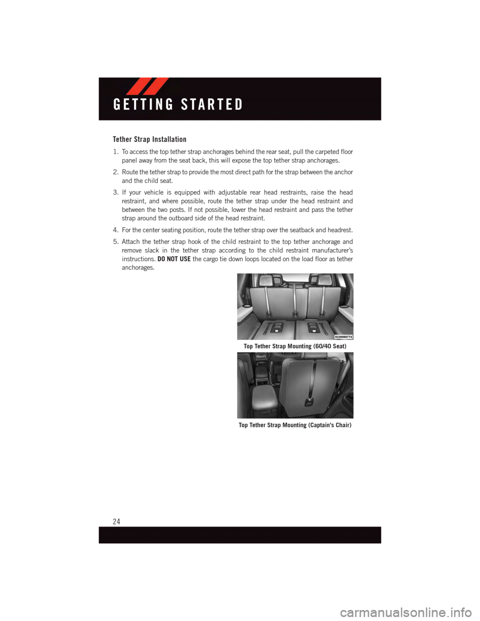
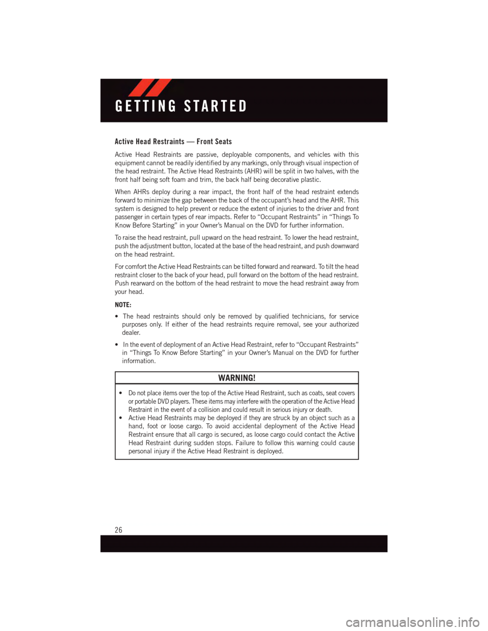
Tether Strap Installation
1. To access the top tether strap anchorages behind the rear seat, pull the carpeted floor
panel away from the seat back, this will expose the top tether strap anchorages.
2. Route the tether strap to provide the most direct path for the strap between the anchor
and the child seat.
3. If your vehicle is equipped with adjustable rear head restraints, raise the head
restraint, and where possible, route the tether strap under the head restraint and
between the two posts. If not possible, lower the head restraint and pass the tether
strap around the outboard side of the head restraint.
4. For the center seating position, route the tether strap over the seatback and headrest.
5. Attach the tether strap hook of the child restraint to the top tether anchorage and
remove slack in the tether strap according to the child restraint manufacturer’s
instructions.DO NOT USEthe cargo tie down loops located on the load floor as tether
anchorages.
Top Tether Strap Mounting (60/40 Seat)
Top Tether Strap Mounting (Captain's Chair)
GETTING STARTED
24
Page 28 of 236

Active Head Restraints — Front Seats
Active Head Restraints are passive, deployable components, and vehicles with this
equipment cannot be readily identified by any markings, only through visual inspection of
the head restraint. The Active Head Restraints (AHR) will be split in two halves, with the
front half being soft foam and trim, the back half being decorative plastic.
When AHRs deploy during a rear impact, the front half of the head restraint extends
forward to minimize the gap between the back of the occupant’s head and the AHR. This
system is designed to help prevent or reduce the extent of injuries to the driver and front
passenger in certain types of rear impacts. Refer to “Occupant Restraints” in “Things To
Know Before Starting” in your Owner’s Manual on the DVD for further information.
To r a i s e t h e h e a d r e s t r a i n t , p u l l u p w a r d o n t h e h e a d r e s t r a i n t . To l o w e r t h e h e a d r e s t r a i n t ,
push the adjustment button, located at the base of the head restraint, and push downward
on the head restraint.
For comfort the Active Head Restraints can be tilted forward and rearward. To tilt the head
restraint closer to the back of your head, pull forward on the bottom of the head restraint.
Push rearward on the bottom of the head restraint to move the head restraint away from
your head.
NOTE:
•Theheadrestraintsshouldonlyberemovedbyqualifiedtechnicians,forservice
purposes only. If either of the head restraints require removal, see your authorized
dealer.
•IntheeventofdeploymentofanActiveHeadRestraint,referto“OccupantRestraints”
in “Things To Know Before Starting” in your Owner’s Manual on the DVD for further
information.
WARNING!
•Do not place items over the top of the Active Head Restraint, such as coats, seat covers
or portable DVD players. These items may interfere with the operation of the Active Head
Restraint in the event of a collision and could result in serious injury or death.
•ActiveHeadRestraintsmaybedeployediftheyarestruckbyanobjectsuchasa
hand, foot or loose cargo. To avoid accidental deployment of the Active Head
Restraint ensure that all cargo is secured, as loose cargo could contact the Active
Head Restraint during sudden stops. Failure to follow this warning could cause
personal injury if the Active Head Restraint is deployed.
GETTING STARTED
26
Page 29 of 236

Head Restraints — Rear Seats
The head restraints on the outboard seats are not adjustable. They automatically fold
forward when the rear seat is folded to a load floor position but do not return to their
normal position when the rear seat is raised. After returning either seat to its upright
position, raise the head restraint until it locks in place. The outboard head restraints are
not removable.
The center head restraint has limited adjustment. Lift upward on the head restraint to
raise it, or push downward on the head restraint to lower it.
WARNING!
Sitting in a seat with the head restraint in its lowered position could result in serious
injury or death in a collision. Always make sure the outboard head restraints are in their
upright positions when the seat is to be occupied.
NOTE:
For proper routing of a Child Seat Tether, refer to “Occupant Restraints” in “Things To
Know Before Starting” in your Owner’s Manual on the DVD for further information.
Power Folding Third Row Head Restraints
For improved visibility when in reverse, the third row head restraints can be folded using
the Uconnect®System.
Press the “Controls” button located on the bottom of the Uconnect®display.
Press the Headrest Fold buttonto power fold the third row head restraints.
NOTE:
•TheheadrestraintscanonlybefoldeddownwardusingtheHeadrestbutton.Thehead
restraints must be raised manually when occupying the third row.
•Donotfoldiftherearepassengersseatedinthethirdrowseats.
GETTING STARTED
27
Page 208 of 236

FUSES
WARNING!
•Whenreplacingablownfuse,alwaysuseanappropriatereplacementfusewiththe
same amp rating as the original fuse. Never replace a fuse with another fuse of
higher amp rating. Never replace a blown fuse with metal wires or any other
material. Failure to use proper fuses may result in serious personal injury, fire and/or
property damage.
•Beforereplacingafuse,makesurethattheignitionisoffandthatalltheother
services are switched off and/or disengaged.
•Ifthereplacedfuseblowsagain,contactanauthorizeddealer.
•Ifageneralprotectionfuseforsafetysystems(airbagsystem,brakingsystem),
power unit systems (engine system, gearbox system) or steering system blows,
contact an authorized dealer.
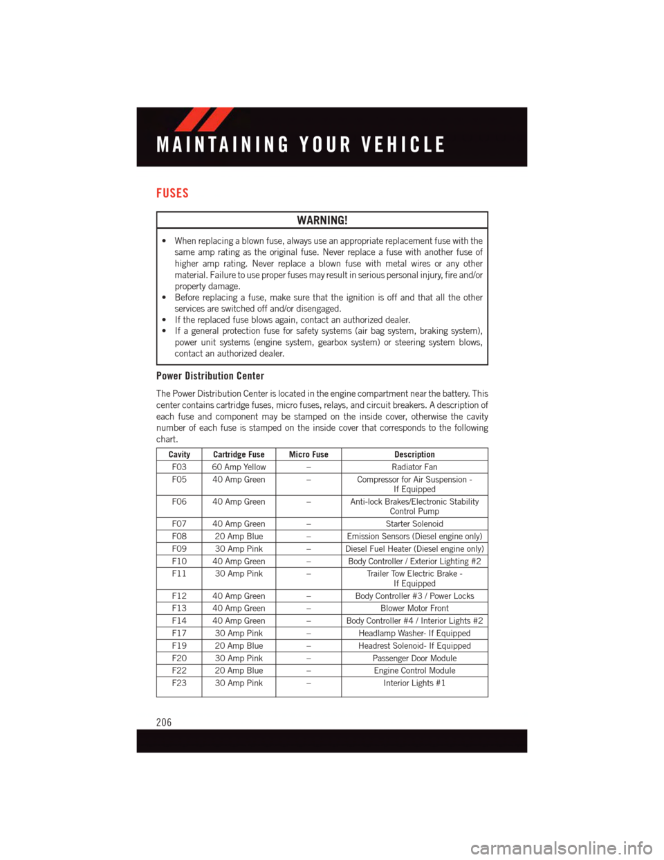
Power Distribution Center
The Power Distribution Center is located in the engine compartment near the battery. This
center contains cartridge fuses, micro fuses, relays, and circuit breakers. A description of
each fuse and component may be stamped on the inside cover, otherwise the cavity
number of each fuse is stamped on the inside cover that corresponds to the following
chart.
Cavity Cartridge Fuse Micro FuseDescription
F03 60 Amp Yellow –Radiator Fan
F05 40 Amp Green –Compressor for Air Suspension -If Equipped
F06 40 Amp Green – Anti-lock Brakes/Electronic StabilityControl Pump
F07 40 Amp Green –Starter Solenoid
F08 20 Amp Blue–EmissionSensors(Dieselengineonly)
F09 30 Amp Pink–DieselFuelHeater(Dieselengineonly)
F10 40 Amp Green – Body Controller / Exterior Lighting #2
F11 30 Amp Pink–Tr a i l e r To w E l e c t r i c B r a k e -If Equipped
F12 40 Amp Green –Body Controller #3 / Power Locks
F13 40 Amp Green –Blower Motor Front
F14 40 Amp Green – Body Controller #4 / Interior Lights #2
F17 30 Amp Pink–Headlamp Washer- If Equipped
F19 20 Amp Blue–Headrest Solenoid- If Equipped
F20 30 Amp Pink–Passenger Door Module
F22 20 Amp Blue–Engine Control Module
F23 30 Amp Pink–Interior Lights #1
MAINTAINING YOUR VEHICLE
206