buttons DODGE DURANGO 2020 User Guide
[x] Cancel search | Manufacturer: DODGE, Model Year: 2020, Model line: DURANGO, Model: DODGE DURANGO 2020Pages: 464, PDF Size: 22.14 MB
Page 66 of 464

64GETTING TO KNOW YOUR VEHICLE
Icon Description
Rear Mode ControlRear Mode Control
The rear airflow distribution mode can be adjusted so air comes from the headliner outlets, the floor outlets or both.
Headliner Mode Headliner Mode
Air comes from the outlets in the headliner. Each of these outlets can be individually adjusted to direct the flow of air. Moving
the air vanes of the outlets to one side shuts off the airflow.
Bi-Level Mode Bi-Level Mode
Air comes from both the headliner outlets and the floor outlets.
NOTE:
In many temperature positions, the Bi-Level mode is designed to provide cooler air out of the headliner outlets and warmer air
from the floor outlets.
Floor Mode Floor Mode
Air comes from the floor outlets.
Rear Blower Control
Rear Blower Control is used to regulate the amount of air forced through the rear climate system. There are seven blower
speeds available. The speeds can be selected using the buttons on the touchscreen. Use the small blower icon (or blower icon
with the downward arrow) to reduce the blower setting, and the large blower icon (or blower icon with the upward arrow) to
increase the blower setting. Blower can also be selected by pressing the blower bar area between the icons.
20_WD_OM_EN_USC_t.book Page 64
Page 68 of 464
66GETTING TO KNOW YOUR VEHICLE
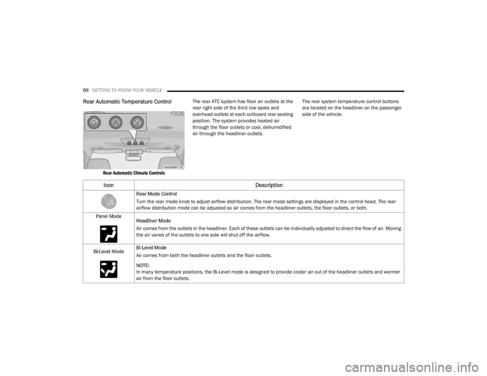
Rear Automatic Temperature Control
Rear Automatic Climate Controls
The rear ATC system has floor air outlets at the
rear right side of the third row seats and
overhead outlets at each outboard rear seating
position. The system provides heated air
through the floor outlets or cool, dehumidified
air through the headliner outlets.
The rear system temperature control buttons
are located on the headliner on the passenger
side of the vehicle.
Icon
Description
Rear Mode Control
Turn the rear mode knob to adjust airflow distribution. The rear mode settings are displayed in the control head. The rear
airflow distribution mode can be adjusted so air comes from the headliner outlets, the floor outlets, or both.
Panel Mode Headliner Mode
Air comes from the outlets in the headliner. Each of these outlets can be individually adjusted to direct the flow of air. Moving
the air vanes of the outlets to one side will shut off the airflow.
Bi-Level Mode Bi-Level Mode
Air comes from both the headliner outlets and the floor outlets.
NOTE:
In many temperature positions, the Bi-Level mode is designed to provide cooler air out of the headliner outlets and warmer
air from the floor outlets.
20_WD_OM_EN_USC_t.book Page 66
Page 78 of 464
76GETTING TO KNOW YOUR VEHICLE
NOTE:
When using the liftgate button on the key fob
to open the liftgate while the vehicle is
locked, only the liftgate will unlock leaving
the other doors to remain locked. Closing the
liftgate will not re-lock the liftgate. The lock
button on the key fob, or the Passive Entry
lock button must be pushed to re-lock.
When using the Passive Entry button to open
the liftgate, and the vehicle doors unlock
(if “Unlock All Doors 1st Press” is selected in
the Passive Entry settings), the liftgate and
vehicle doors must be locked using the lock
button on the key fob, the Passive Entry lock
button, or the lock buttons on the interior
front door panels.
The power liftgate may also be opened or closed
by pushing the liftgate button located on the
front overhead console. If the liftgate is fully
open, the liftgate can be closed by pushing the
liftgate button located on left rear trim panel,
near the liftgate opening. If the liftgate is in
motion, pushing the liftgate button located on
left rear trim panel will reverse the liftgate. When the liftgate button on the key fob is
pushed two times, the turn signals will flash to
signal that the liftgate is opening or closing
(if "Flash Lamps with Lock" is enabled in the
Uconnect settings), and the liftgate chime will
be audible. Refer to "Uconnect Settings" in
"Multimedia” for further information.
NOTE:In the event of a power malfunction to the lift
-
gate, an emergency liftgate latch release can
be used to open the liftgate. The emergency
liftgate latch release can be accessed
through a snap-in cover located on the lift-
gate trim panel.
If liftgate is left open for an extended period
of time, the liftgate may need to be closed
manually to reset power liftgate functionality. NOTE:
The power liftgate buttons will not operate if
the vehicle is in gear or the vehicle speed is
above 0 mph (0 km/h).
The power liftgate will not operate in
temperatures below −22°F (−30°C) or
temperatures above 150°F (65°C). Be sure
to remove any buildup of snow or ice from the
liftgate before pushing any of the power lift
-
gate switches.
If anything obstructs the power liftgate while
it is closing or opening, the liftgate will auto -
matically reverse to the closed or open posi -
tion, provided it meets sufficient resistance.
There are also pinch sensors attached to the
side of the liftgate. Light pressure anywhere
along these strips will cause the liftgate to
return to the open position.
If the liftgate is not fully open, push the lift -
gate button on the key fob twice to operate
the liftgate.WARNING!
During power operation, personal injury or
cargo damage may occur. Ensure the liftgate
travel path is clear. Make sure the liftgate is
closed and latched before driving away.
20_WD_OM_EN_USC_t.book Page 76
Page 80 of 464
78GETTING TO KNOW YOUR VEHICLE
(Continued)
(Continued)
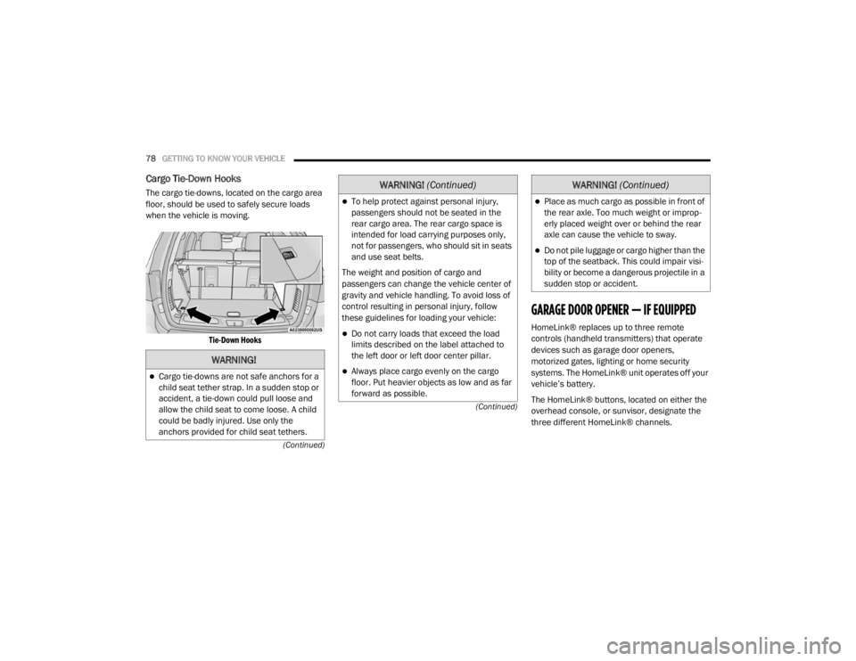
Cargo Tie-Down Hooks
The cargo tie-downs, located on the cargo area
floor, should be used to safely secure loads
when the vehicle is moving.
Tie-Down Hooks
GARAGE DOOR OPENER — IF EQUIPPED
HomeLink® replaces up to three remote
controls (handheld transmitters) that operate
devices such as garage door openers,
motorized gates, lighting or home security
systems. The HomeLink® unit operates off your
vehicle’s battery.
The HomeLink® buttons, located on either the
overhead console, or sunvisor, designate the
three different HomeLink® channels.
WARNING!
Cargo tie-downs are not safe anchors for a
child seat tether strap. In a sudden stop or
accident, a tie-down could pull loose and
allow the child seat to come loose. A child
could be badly injured. Use only the
anchors provided for child seat tethers.
To help protect against personal injury,
passengers should not be seated in the
rear cargo area. The rear cargo space is
intended for load carrying purposes only,
not for passengers, who should sit in seats
and use seat belts.
The weight and position of cargo and
passengers can change the vehicle center of
gravity and vehicle handling. To avoid loss of
control resulting in personal injury, follow
these guidelines for loading your vehicle:
Do not carry loads that exceed the load
limits described on the label attached to
the left door or left door center pillar.
Always place cargo evenly on the cargo
floor. Put heavier objects as low and as far
forward as possible.
WARNING! (Continued)
Place as much cargo as possible in front of
the rear axle. Too much weight or improp -
erly placed weight over or behind the rear
axle can cause the vehicle to sway.
Do not pile luggage or cargo higher than the
top of the seatback. This could impair visi-
bility or become a dangerous projectile in a
sudden stop or accident.
WARNING! (Continued)
20_WD_OM_EN_USC_t.book Page 78
Page 81 of 464
GETTING TO KNOW YOUR VEHICLE79
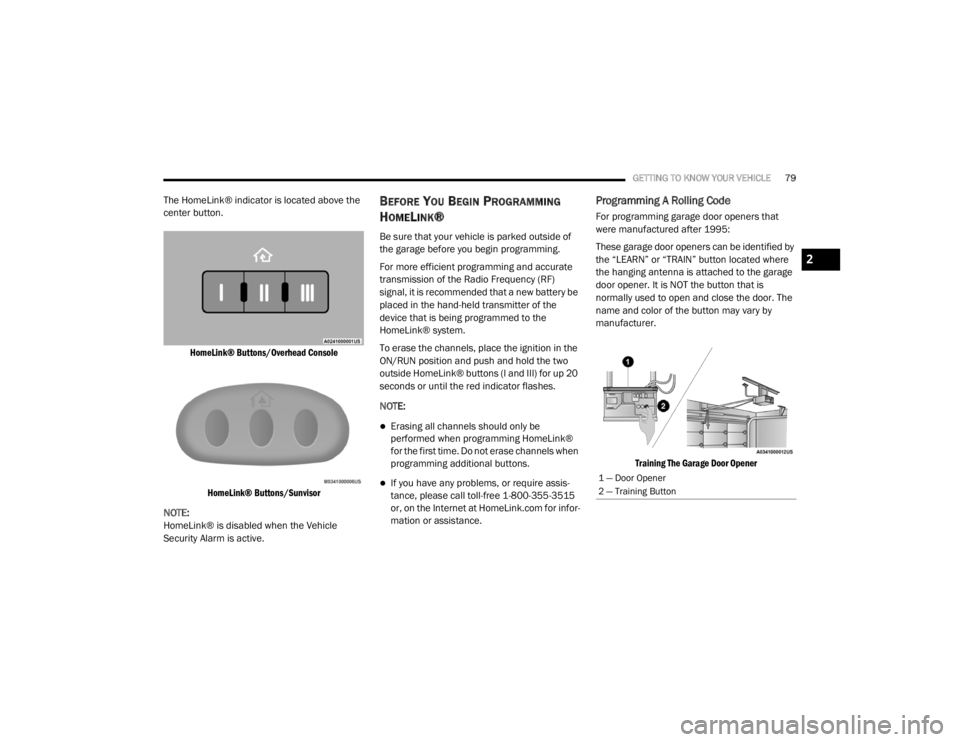
The HomeLink® indicator is located above the
center button.
HomeLink® Buttons/Overhead ConsoleHomeLink® Buttons/Sunvisor
NOTE:
HomeLink® is disabled when the Vehicle
Security Alarm is active.BEFORE YOU BEGIN PROGRAMMING
H
OMELINK®
Be sure that your vehicle is parked outside of
the garage before you begin programming.
For more efficient programming and accurate
transmission of the Radio Frequency (RF)
signal, it is recommended that a new battery be
placed in the hand-held transmitter of the
device that is being programmed to the
HomeLink® system.
To erase the channels, place the ignition in the
ON/RUN position and push and hold the two
outside HomeLink® buttons (I and III) for up 20
seconds or until the red indicator flashes.
NOTE:
Erasing all channels should only be
performed when programming HomeLink®
for the first time. Do not erase channels when
programming additional buttons.
If you have any problems, or require assis -
tance, please call toll-free 1-800-355-3515
or, on the Internet at HomeLink.com for infor -
mation or assistance.
Programming A Rolling Code
For programming garage door openers that
were manufactured after 1995:
These garage door openers can be identified by
the “LEARN” or “TRAIN” button located where
the hanging antenna is attached to the garage
door opener. It is NOT the button that is
normally used to open and close the door. The
name and color of the button may vary by
manufacturer.
Training The Garage Door Opener
1 — Door Opener
2 — Training Button
2
20_WD_OM_EN_USC_t.book Page 79
Page 82 of 464
80GETTING TO KNOW YOUR VEHICLE
1. Place the ignition in the ON/RUN position.
NOTE:
For vehicles equipped with Keyless Enter-N-Go,
place the ignition in the RUN position with the
engine on. Make sure while programming
HomeLink® with the engine on that your vehicle
is outside of your garage, or that the garage
door remains open at all times.
2. Place the hand-held transmitter 1 to
3 inches (3 to 8 cm) away from the
HomeLink® button you wish to program
while keeping the HomeLink® indicator
light in view.
3. Push and hold the HomeLink® button you want to program while you push and hold
the hand-held transmitter button.
4. Continue to hold both buttons and observe the indicator light. The HomeLink®
indicator will flash slowly and then rapidly
after HomeLink® has received the
frequency signal from the hand-held
transmitter. Release both buttons after the
indicator light changes from slow to rapid. 5. At the garage door opener (in the garage),
locate the “LEARN” or “TRAINING” button.
This can usually be found where the
hanging antenna wire is attached to the
garage door opener/device motor. Firmly
push and release the “LEARN” or
“TRAINING” button. On some garage door
openers/devices there may be a light that
blinks when the garage door opener/device
is in the LEARN/TRAIN mode.
NOTE:
You have 30 seconds in which to initiate the
next step after the LEARN button has been
pushed.
6. Return to the vehicle and push the programmed HomeLink® button twice
(holding the button for two seconds each
time). If the garage door opener/device
activates, programming is complete.
NOTE:
If the garage door opener/device does not acti -
vate, push the button a third time (for two
seconds) to complete the training.
To program the remaining two HomeLink®
buttons, repeat each step for each remain -
ing button. DO NOT erase the channels.Programming A Non-Rolling Code
For programming garage door openers
manufactured before 1995:
1. Place the ignition in the ON/RUN position.
NOTE:
For vehicles equipped with Keyless Enter-N-Go,
place the ignition in the RUN position with the
engine on. Make sure while programming
HomeLink® with the engine on that your vehicle
is outside of your garage, or that the garage
door remains open at all times.
2. Place the hand-held transmitter 1 to 3 inches (3 to 8 cm) away from the
HomeLink® button you wish to program
while keeping the HomeLink® indicator
light in view.
3. Push and hold the Homelink® button you want to program while you push and hold
the hand-held transmitter button.
4. Continue to hold both buttons and observe the indicator light. The Homelink® indicator
will flash slowly and then rapidly after
HomeLink® has received the frequency
signal from the hand-held transmitter.
20_WD_OM_EN_USC_t.book Page 80
Page 83 of 464

GETTING TO KNOW YOUR VEHICLE81
Release both buttons after the indicator
light changes from slow to rapid.
5. Push and hold the programmed HomeLink® button and observe the
indicator light.
If the indicator light stays on constantly,
programming is complete and the garage
door/device should activate when the
HomeLink® button is pushed.
To program the two remaining Home -
Link® buttons, repeat each step for each
remaining button. DO NOT erase the
channels.
CANADIAN/GATE OPERATOR
P
ROGRAMMING
For programming transmitters in Canada/
United States that require the transmitter
signals to “time-out” after several seconds of
transmission:
Canadian Radio Frequency (RF) laws require
transmitter signals to time-out (or quit) after
several seconds of transmission, which may not
be long enough for HomeLink® to pick up the
signal during programming. Similar to this Canadian law, some U.S. gate
operators are designed to time-out in the same
manner.
It may be helpful to unplug the device during the
cycling process to prevent possible overheating
of the garage door or gate motor.
1. Place the ignition in the ON/RUN position.
NOTE:
For vehicles equipped with Keyless Enter-N-Go,
place the ignition in the RUN position with the
engine on. Make sure while programming
HomeLink® with the engine on that your vehicle
is outside of your garage, or that the garage
door remains open at all times.
2. Place the hand-held transmitter 1 to
3 inches (3 to 8 cm) away from the
HomeLink® button you wish to program
while keeping the HomeLink® indicator
light in view.
3. Continue to push and hold the HomeLink® button while you push and release (“cycle”)
your hand-held transmitter every two
seconds until HomeLink® has successfully
accepted the frequency signal. The indicator light will flash slowly and then
rapidly when fully trained.
4. Watch for the HomeLink® indicator to change flash rates. When it changes, it is
programmed. It may take up to 30 seconds
or longer in rare cases. The garage door
may open and close while you are
programming.
5. Push and hold the programmed HomeLink® button and observe the
indicator light.
NOTE:
If the indicator light stays on constantly,
programming is complete and the garage
door/device should activate when the Home -
Link® button is pushed.
To program the two remaining HomeLink®
buttons, repeat each step for each remaining
button. DO NOT erase the channels.
If you unplugged the garage door opener/
device for programming, plug it back in at this
time.
2
20_WD_OM_EN_USC_t.book Page 81
Page 84 of 464
82GETTING TO KNOW YOUR VEHICLE
USING HOMELINK®
To operate, place the ignition in the ON/RUN
position and then press and release the
programmed HomeLink® button. Activation will
now occur for the programmed device (i.e.,
garage door opener, gate operator, security
system, entry door lock, home/office lighting,
etc.,). The hand-held transmitter of the device
may also be used at any time. If the ignition is
placed in the OFF position, HomeLink® will
remain active for three minutes. During this
time, if the vehicle is locked, HomeLink® is
disabled.
SECURITY
It is advised to erase all channels before you sell
or turn in your vehicle.
To do this, push and hold the two outside
buttons for 20 seconds until the red indicator
flashes. NOTE:
All channels will be erased. Individual channels
cannot be erased.
The HomeLink® Universal Transceiver is
disabled when the Vehicle Security Alarm is
active.
TROUBLESHOOTING TIPS
If you are having trouble programming
HomeLink®, here are some of the most
common solutions:
Replace the battery in the garage door
opener hand-held transmitter.
Push the LEARN button on the garage door
opener to complete the training for a rolling
code.
Did you unplug the device for programming
and remember to plug it back in?
If you have any problems, or require assistance,
please call toll-free 1-800-355-3515 or, on the
Internet at HomeLink.com for information or
assistance.
WARNING!
Vehicle exhaust contains carbon monoxide,
a dangerous gas. Do not run your vehicle in
the garage while programming the trans -
ceiver. Exhaust gas can cause serious
injury or death.
Your motorized door or gate will open and
close while you are programming the
universal transceiver. Do not program the
transceiver if people, pets or other objects
are in the path of the door or gate. Only use
this transceiver with a garage door opener
that has a “stop and reverse” feature as
required by Federal safety standards. This
includes most garage door opener models
manufactured after 1982. Do not use a
garage door opener without these safety
features.
20_WD_OM_EN_USC_t.book Page 82
Page 102 of 464
100GETTING TO KNOW YOUR INSTRUMENT PANEL
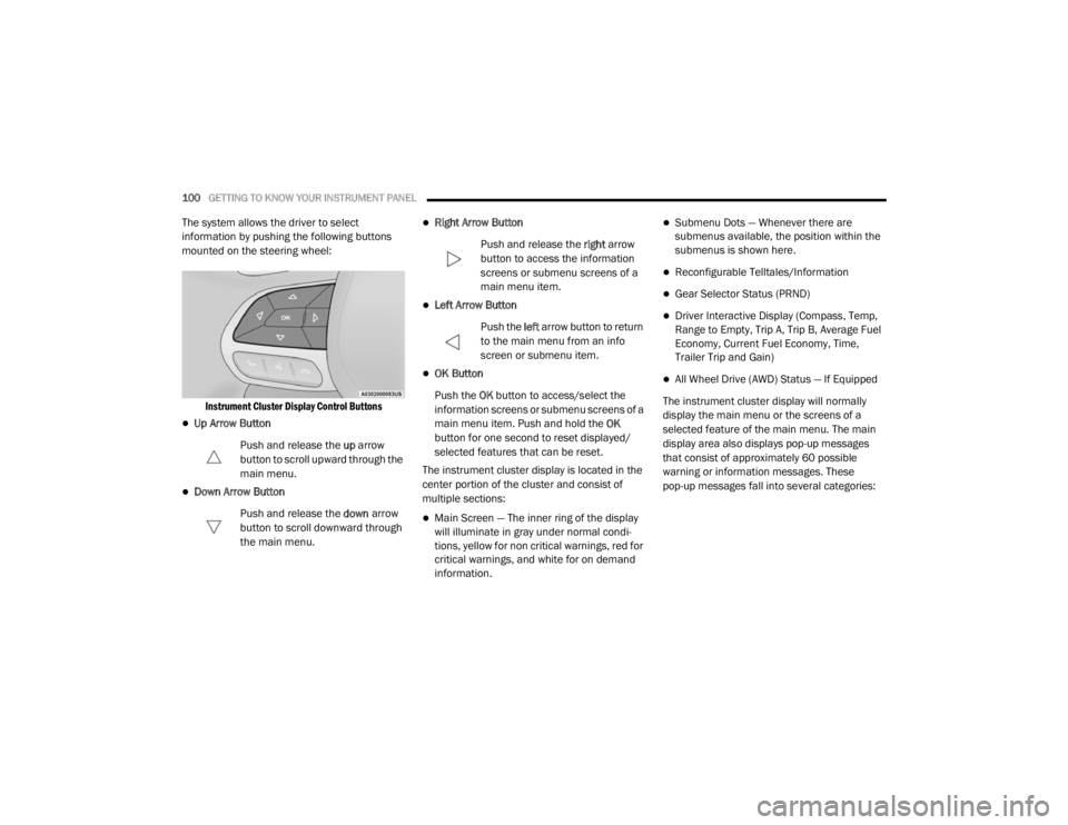
The system allows the driver to select
information by pushing the following buttons
mounted on the steering wheel:
Instrument Cluster Display Control Buttons
Up Arrow Button
Push and release the up arrow
button to scroll upward through the
main menu.
Down Arrow Button
Push and release the down arrow
button to scroll downward through
the main menu.
Right Arrow Button
Push and release the right arrow
button to access the information
screens or submenu screens of a
main menu item.
Left Arrow Button
Push the left arrow button to return
to the main menu from an info
screen or submenu item.
OK Button
Push the OK button to access/select the
information screens or submenu screens of a
main menu item. Push and hold the OK
button for one second to reset displayed/
selected features that can be reset.
The instrument cluster display is located in the
center portion of the cluster and consist of
multiple sections:
Main Screen — The inner ring of the display
will illuminate in gray under normal condi -
tions, yellow for non critical warnings, red for
critical warnings, and white for on demand
information.
Submenu Dots — Whenever there are
submenus available, the position within the
submenus is shown here.
Reconfigurable Telltales/Information
Gear Selector Status (PRND)
Driver Interactive Display (Compass, Temp,
Range to Empty, Trip A, Trip B, Average Fuel
Economy, Current Fuel Economy, Time,
Trailer Trip and Gain)
All Wheel Drive (AWD) Status — If Equipped
The instrument cluster display will normally
display the main menu or the screens of a
selected feature of the main menu. The main
display area also displays pop-up messages
that consist of approximately 60 possible
warning or information messages. These
pop-up messages fall into several categories:
20_WD_OM_EN_USC_t.book Page 100
Page 103 of 464

GETTING TO KNOW YOUR INSTRUMENT PANEL101
Five Second Stored Messages
When the appropriate conditions occur, this
type of message takes control of the main
display area for five seconds and then
returns to the previous screen. Most of the
messages of this type are then stored (as
long as the condition that activated it
remains active) and can be reviewed from
the “Messages” main menu item. Examples
of this message type are “Right Front Turn
Signal Lamp Out” and “Low Tire Pressure.”
Unstored Messages
This message type is displayed indefinitely or
until the condition that activated the
message is cleared. Examples of this
message type are “Turn Signal On” (if a turn
signal is left on) and “Lights On” (if driver
leaves the vehicle with the lights on).
Unstored Messages Until RUN
These messages deal primarily with the
Remote Start feature. This message type is
displayed until the ignition is in the RUN
state. Examples of this message type are
“Remote Start Canceled - Door Ajar” and
“Press Brake Pedal and Push Button to
Start.”
Five Second Unstored Messages
When the appropriate conditions occur, this
type of message takes control of the main
display area for five seconds and then
returns to the previous screen. An example of
this message type is “Automatic High Beams
On.”
ENGINE OIL LIFE RESET
Oil Change Required
Your vehicle is equipped with an engine oil
change indicator system. The “Oil Change
Required” message will display in the
instrument cluster display for five seconds after
a single chime has sounded, to indicate the next
scheduled oil change interval. The engine oil
change indicator system is duty cycle based,
which means the engine oil change interval may
fluctuate, dependent upon your personal
driving style.
Unless reset, this message will continue to
display each time the ignition is placed in the
ON/RUN position. To turn off the message
temporarily, push and release the OK or arrow
buttons. To reset the oil change indicator system (after
performing the scheduled maintenance), refer
to the following procedure.
Vehicles Equipped With Keyless Enter-N-Go —
Ignition
Use the steering wheel instrument cluster
display controls for the following procedure(s):
1. Without pressing the brake pedal, push the
ENGINE START/STOP button and place the
ignition in the ON/RUN position (do not
start the engine).
2. Push and release the down arrow button to
scroll downward through the main menu to
“Vehicle Info.”
3. Push and release the right arrow button to
access the ”Oil Life” screen.
4. Push and hold the OK button to reset oil life.
If conditions are met, the gauge and
numeric display will update to show 100%.
If conditions are not met a pop-up message
of “To reset oil life engine must be off with
ignition in run” will be displayed (for five
seconds), and the user will remain at the Oil
Life screen.
3
20_WD_OM_EN_USC_t.book Page 101