warning light DODGE DURANGO 2020 Manual PDF
[x] Cancel search | Manufacturer: DODGE, Model Year: 2020, Model line: DURANGO, Model: DODGE DURANGO 2020Pages: 464, PDF Size: 22.14 MB
Page 278 of 464
276IN CASE OF EMERGENCY
RUN FLAT TIRES
SRT models are equipped with “run flat” tires.
Run flat tires allow the vehicle to be driven
approximately 50 miles (80 km) at 50 mph
(80 km/h). Tire service should be obtained to
avoid prolonged run flat feature usage.
JACK LOCATION
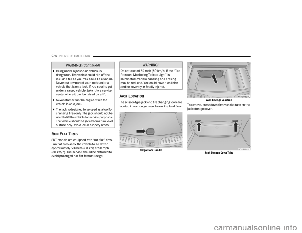
The scissor-type jack and tire changing tools are
located in rear cargo area, below the load floor.
Cargo Floor Handle Jack Storage Location
To remove, press down firmly on the tabs on the
jack storage cover.
Jack Storage Cover Tabs
Being under a jacked-up vehicle is
dangerous. The vehicle could slip off the
jack and fall on you. You could be crushed.
Never put any part of your body under a
vehicle that is on a jack. If you need to get
under a raised vehicle, take it to a service
center where it can be raised on a lift.
Never start or run the engine while the
vehicle is on a jack.
The jack is designed to be used as a tool for
changing tires only. The jack should not be
used to lift the vehicle for service purposes.
The vehicle should be jacked on a firm level
surface only. Avoid ice or slippery areas.
WARNING! (Continued)WARNING!
Do not exceed 50 mph (80 km/h) if the “Tire
Pressure Monitoring Telltale Light” is
illuminated. Vehicle handling and braking
may be reduced. You could have a collision
and be severely or fatally injured.
20_WD_OM_EN_USC_t.book Page 276
Page 283 of 464
IN CASE OF EMERGENCY281
Front Jacking Location
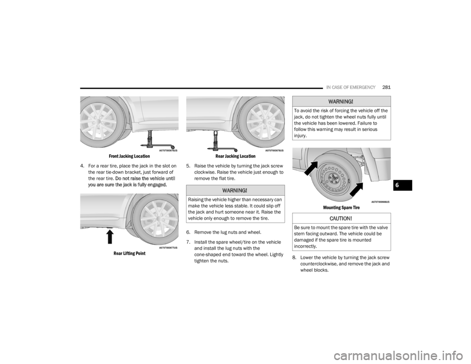
4. For a rear tire, place the jack in the slot on the rear tie-down bracket, just forward of
the rear tire. Do not raise the vehicle until
you are sure the jack is fully engaged.
Rear Lifting Point Rear Jacking Location
5. Raise the vehicle by turning the jack screw clockwise. Raise the vehicle just enough to
remove the flat tire.
6. Remove the lug nuts and wheel.
7. Install the spare wheel/tire on the vehicle and install the lug nuts with the
cone-shaped end toward the wheel. Lightly
tighten the nuts.
Mounting Spare Tire
8. Lower the vehicle by turning the jack screw counterclockwise, and remove the jack and
wheel blocks.
WARNING!
Raising the vehicle higher than necessary can
make the vehicle less stable. It could slip off
the jack and hurt someone near it. Raise the
vehicle only enough to remove the tire.
WARNING!
To avoid the risk of forcing the vehicle off the
jack, do not tighten the wheel nuts fully until
the vehicle has been lowered. Failure to
follow this warning may result in serious
injury.
CAUTION!
Be sure to mount the spare tire with the valve
stem facing outward. The vehicle could be
damaged if the spare tire is mounted
incorrectly.
6
20_WD_OM_EN_USC_t.book Page 281
Page 285 of 464
IN CASE OF EMERGENCY283
NOTE:
Double check to ensure the tire is snug against
the underbody of the vehicle. Damage to the
winch cable may result if the vehicle is driven
with the tire loose.
13. Lower the jack to the fully closed position.
Return the tools to the proper positions in
the tool bag. Fold the flap on the tool bag
under the tools and roll the tools in the bag
underneath the others. Use the hook and
loop fasteners to secure the tool bag to the
jack with the lug wrench on the forward side
of the jack. Expand the jack on the bracket
by turning the thumb screw clockwise until
it is tight to prevent rattles.
14. Reinstall the plastic plug into the floor of the cargo area. Roll up and store the Jack, Tool
Kit and Tire Changing Instructions. Reinstall
the cover for the jack in the rear storage bin. 15. Have the aluminum road wheel and tire
repaired as soon as possible and properly
secure the spare tire, jack and tool kit.
ROAD TIRE INSTALLATION
1. Mount the road tire on the axle.
2. Install the remaining lug nuts with the cone shaped end of the nut toward the wheel.
Lightly tighten the lug nuts. 3. Lower the vehicle to the ground by turning
the jack handle counterclockwise.
4. Refer to “Wheel and Tire Torque Specifi -
cations” in “Technical Specifications” for
proper lug nut torque.
5. After 25 miles (40 km), check the lug nut torque with a torque wrench to ensure that
all lug nuts are properly seated against the
wheel.
JUMP STARTING
If your vehicle has a discharged battery, it can
be jump started using a set of jumper cables
and a battery in another vehicle, or by using a
portable battery booster pack. Jump starting
can be dangerous if done improperly, so please
follow the procedures in this section carefully.
CAUTION!
The winch mechanism is designed for use
with the jack wrench extension tool only. Use
of air wrench or power tool may damage the
winch.
WARNING!
A loose tire or jack thrown forward in a
collision or hard stop, could endanger the
occupants of the vehicle. Always stow the jack
parts and the spare tire in the places
provided.
WARNING!
To avoid the risk of forcing the vehicle off the
jack, do not tighten the wheel nuts fully until
the vehicle has been lowered. Failure to
follow this warning may result in serious
injury.
WARNING!
Do not attempt jump starting if the battery is
frozen. It could rupture or explode and cause
personal injury.
6
20_WD_OM_EN_USC_t.book Page 283
Page 309 of 464
SERVICING AND MAINTENANCE307
(Continued)
CHECKING OIL LEVEL
To ensure proper lubrication of your vehicle's
engine, the engine oil must be maintained at
the correct level. Check the oil level at regular
intervals, such as every fuel stop. The best time
to check the engine oil level is about five
minutes after a fully warmed up engine is shut
off.
Checking the oil while the vehicle is on level
ground will improve the accuracy of the oil level
readings. Always maintain the oil level within
the SAFE zone on the dipstick. Adding one quart
of oil when the reading is at the bottom of the
SAFE zone will result in a reading at the top of
the safe zone on these engines.
ADDING WASHER FLUID
The instrument cluster display will indicate
when the washer fluid level is low. When the
sensor detects a low fluid level, the windshield
will light on the vehicle graphic outline and the
“WASHER FLUID LOW” message will be
displayed.
The fluid reservoir for the windshield washers
and the rear window washer is shared. The fluid
reservoir is located in the engine compartment,
be sure to check the fluid level at regular
intervals. Fill the reservoir with windshield
washer solvent only (not radiator antifreeze).
When refilling the washer fluid reservoir, take
some washer fluid and apply it to a cloth or
towel and wipe clean the wiper blades, this will
help blade performance. To prevent freeze-up
of your windshield washer system in cold
weather, select a solution or mixture that meets
or exceeds the temperature range of your
climate. This rating information can be found on
most washer fluid containers.
MAINTENANCE-FREE BATTERY
Your vehicle is equipped with a
maintenance-free battery. Water will never have
to be added, nor is periodic maintenance
required.
CAUTION!
Overfilling or underfilling will cause oil
aeration or loss of oil pressure. This could
damage your engine.
WARNING!
Commercially available windshield washer
solvents are flammable. They could ignite and
burn you. Care must be exercised when filling
or working around the washer solution.
WARNING!
Battery fluid is a corrosive acid solution and
can burn or even blind you. Do not allow
battery fluid to contact your eyes, skin, or
clothing. Do not lean over a battery when
attaching clamps. If acid splashes in eyes
or on skin, flush the area immediately with
large amounts of water. Refer to “Jump
Starting Procedure” in “In Case Of Emer -
gency” for further information.
7
20_WD_OM_EN_USC_t.book Page 307
Page 327 of 464
SERVICING AND MAINTENANCE325
(Continued)
BRAKE SYSTEM
In order to ensure brake system performance,
all brake system components should be
inspected periodically. Refer to the
“Maintenance Plan” in this section for the
proper maintenance intervals.
Fluid Level Check — Brake Master Cylinder
The fluid level of the master cylinder should be
checked whenever the vehicle is serviced, or
immediately if the brake system warning light is
on. If necessary, add fluid to bring level within
the designated marks on the side of the
reservoir of the brake master cylinder. Be sure
to clean the top of the master cylinder area
before removing cap. With disc brakes, fluid level can be expected to
fall as the brake pads wear. Brake fluid level
should be checked when pads are replaced. If
the brake fluid is abnormally low, check the
system for leaks.
Refer to “Fluids And Lubricants” in “Technical
Specifications” for further information.
WARNING!
Riding the brakes can lead to brake failure
and possibly a collision. Driving with your foot
resting or riding on the brake pedal can result
in abnormally high brake temperatures,
excessive lining wear, and possible brake
damage. You would not have your full braking
capacity in an emergency.WARNING!
Use only manufacturer's recommended
brake fluid. Refer to “Fluids And Lubri
-
cants” in “Technical Specifications” for
further information. Using the wrong type of
brake fluid can severely damage your brake
system and/or impair its performance. The
proper type of brake fluid for your vehicle
is also identified on the original factory
installed hydraulic master cylinder
reservoir.
To avoid contamination from foreign matter
or moisture, use only new brake fluid or
fluid that has been in a tightly closed
container. Keep the master cylinder reser -
voir cap secured at all times. Brake fluid in
a open container absorbs moisture from
the air resulting in a lower boiling point. This
may cause it to boil unexpectedly during
hard or prolonged braking, resulting in
sudden brake failure. This could result in a
collision.
Overfilling the brake fluid reservoir can
result in spilling brake fluid on hot engine
parts, causing the brake fluid to catch fire.
Brake fluid can also damage painted and
vinyl surfaces, care should be taken to
avoid its contact with these surfaces.
Do not allow petroleum based fluid to
contaminate the brake fluid. Brake seal
components could be damaged, causing
partial or complete brake failure. This could
result in a collision.
WARNING! (Continued)
7
20_WD_OM_EN_USC_t.book Page 325
Page 340 of 464
338SERVICING AND MAINTENANCE
Tread Wear Indicators
Tread wear indicators are in the original
equipment tires to help you in determining
when your tires should be replaced.
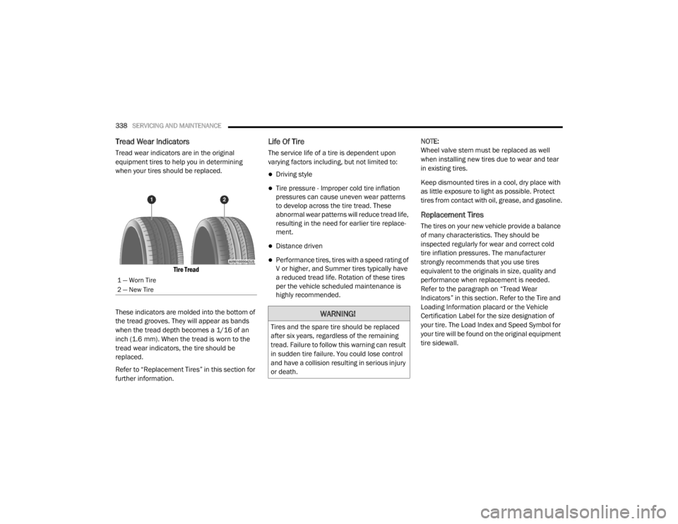
Tire Tread
These indicators are molded into the bottom of
the tread grooves. They will appear as bands
when the tread depth becomes a 1/16 of an
inch (1.6 mm). When the tread is worn to the
tread wear indicators, the tire should be
replaced.
Refer to “Replacement Tires” in this section for
further information.
Life Of Tire
The service life of a tire is dependent upon
varying factors including, but not limited to:
Driving style
Tire pressure - Improper cold tire inflation
pressures can cause uneven wear patterns
to develop across the tire tread. These
abnormal wear patterns will reduce tread life,
resulting in the need for earlier tire replace -
ment.
Distance driven
Performance tires, tires with a speed rating of
V or higher, and Summer tires typically have
a reduced tread life. Rotation of these tires
per the vehicle scheduled maintenance is
highly recommended. NOTE:
Wheel valve stem must be replaced as well
when installing new tires due to wear and tear
in existing tires.
Keep dismounted tires in a cool, dry place with
as little exposure to light as possible. Protect
tires from contact with oil, grease, and gasoline.
Replacement Tires
The tires on your new vehicle provide a balance
of many characteristics. They should be
inspected regularly for wear and correct cold
tire inflation pressures. The manufacturer
strongly recommends that you use tires
equivalent to the originals in size, quality and
performance when replacement is needed.
Refer to the paragraph on “Tread Wear
Indicators” in this section. Refer to the Tire and
Loading Information placard or the Vehicle
Certification Label for the size designation of
your tire. The Load Index and Speed Symbol for
your tire will be found on the original equipment
tire sidewall.
1 — Worn Tire
2 — New Tire
WARNING!
Tires and the spare tire should be replaced
after six years, regardless of the remaining
tread. Failure to follow this warning can result
in sudden tire failure. You could lose control
and have a collision resulting in serious injury
or death.
20_WD_OM_EN_USC_t.book Page 338
Page 352 of 464
350
TECHNICAL SPECIFICATIONS
IDENTIFICATION DATA
VEHICLE IDENTIFICATION NUMBER
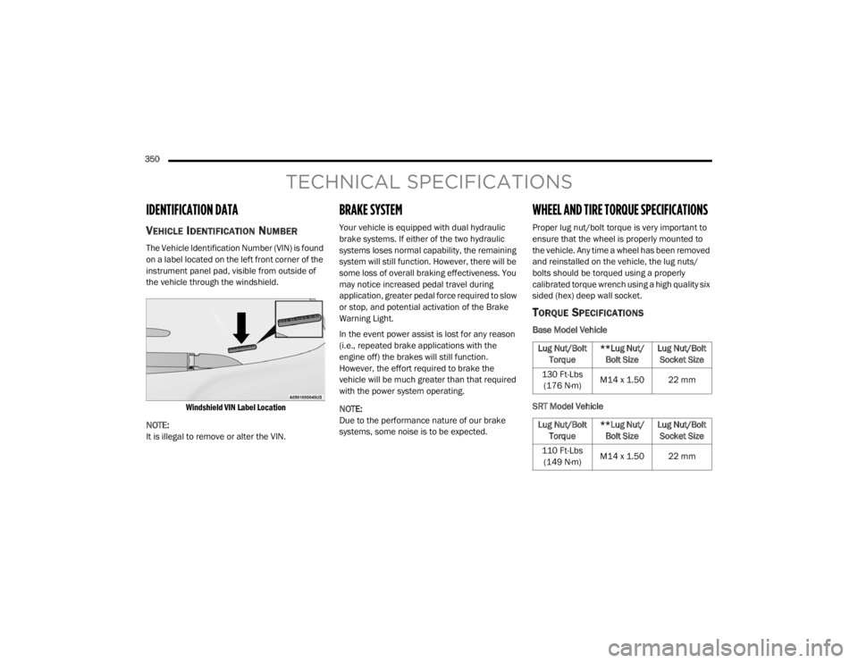
The Vehicle Identification Number (VIN) is found
on a label located on the left front corner of the
instrument panel pad, visible from outside of
the vehicle through the windshield.
Windshield VIN Label Location
NOTE:
It is illegal to remove or alter the VIN.
BRAKE SYSTEM
Your vehicle is equipped with dual hydraulic
brake systems. If either of the two hydraulic
systems loses normal capability, the remaining
system will still function. However, there will be
some loss of overall braking effectiveness. You
may notice increased pedal travel during
application, greater pedal force required to slow
or stop, and potential activation of the Brake
Warning Light.
In the event power assist is lost for any reason
(i.e., repeated brake applications with the
engine off) the brakes will still function.
However, the effort required to brake the
vehicle will be much greater than that required
with the power system operating.
NOTE:
Due to the performance nature of our brake
systems, some noise is to be expected.
WHEEL AND TIRE TORQUE SPECIFICATIONS
Proper lug nut/bolt torque is very important to
ensure that the wheel is properly mounted to
the vehicle. Any time a wheel has been removed
and reinstalled on the vehicle, the lug nuts/
bolts should be torqued using a properly
calibrated torque wrench using a high quality six
sided (hex) deep wall socket.
TORQUE SPECIFICATIONS
Base Model Vehicle
SRT Model Vehicle
Lug Nut/Bolt Torque **Lug Nut/
Bolt Size Lug Nut/Bolt
Socket Size
130 Ft-Lbs (176 N·m) M14 x 1.50 22 mm
Lug Nut/Bolt Torque **Lug Nut/
Bolt Size Lug Nut/Bolt
Socket Size
110 Ft-Lbs (149 N·m) M14 x 1.50 22 mm
20_WD_OM_EN_USC_t.book Page 350
Page 353 of 464
TECHNICAL SPECIFICATIONS351
**Use only authorized dealer recommended
lug nuts/bolts and clean or remove any dirt or
oil before tightening.
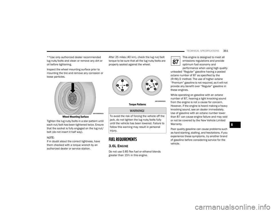
Inspect the wheel mounting surface prior to
mounting the tire and remove any corrosion or
loose particles.
Wheel Mounting Surface
Tighten the lug nuts/bolts in a star pattern until
each nut/bolt has been tightened twice. Ensure
that the socket is fully engaged on the lug nut/
bolt (do not insert it half way).
NOTE:
If in doubt about the correct tightness, have
them checked with a torque wrench by an
authorized dealer or service station. After 25 miles (40 km), check the lug nut/bolt
torque to be sure that all the lug nuts/bolts are
properly seated against the wheel.
Torque Patterns
FUEL REQUIREMENTS
3.6L ENGINE
Do not use E-85 flex fuel or ethanol blends
greater than 15% in this engine. This engine is designed to meet all
emissions regulations and provide
optimum fuel economy and
performance when using high quality
unleaded “Regular” gasoline having a posted
octane number of 87 as specified by the
(R+M)/2 method. The use of higher octane
“Premium” gasoline is not required, as it will not
provide any benefit over “Regular” gasoline in
these engines.
While operating on gasoline with an octane
number of 87, hearing a light knocking sound
from the engine is not a cause for concern.
However, if the engine is heard making a heavy
knocking sound, see an dealer immediately.
Use of gasoline with an octane number lower
than 87 can cause engine failure and may void
or not be covered by the New Vehicle Limited
Warranty.
Poor quality gasoline can cause problems such
as hard starting, stalling, and hesitations. If you
experience these symptoms, try another brand
of gasoline before considering service for the
vehicle.
WARNING!
To avoid the risk of forcing the vehicle off the
jack, do not tighten the lug nuts/bolts fully
until the vehicle has been lowered. Failure to
follow this warning may result in personal
injury.
8
20_WD_OM_EN_USC_t.book Page 351
Page 356 of 464
354TECHNICAL SPECIFICATIONS
(Continued)
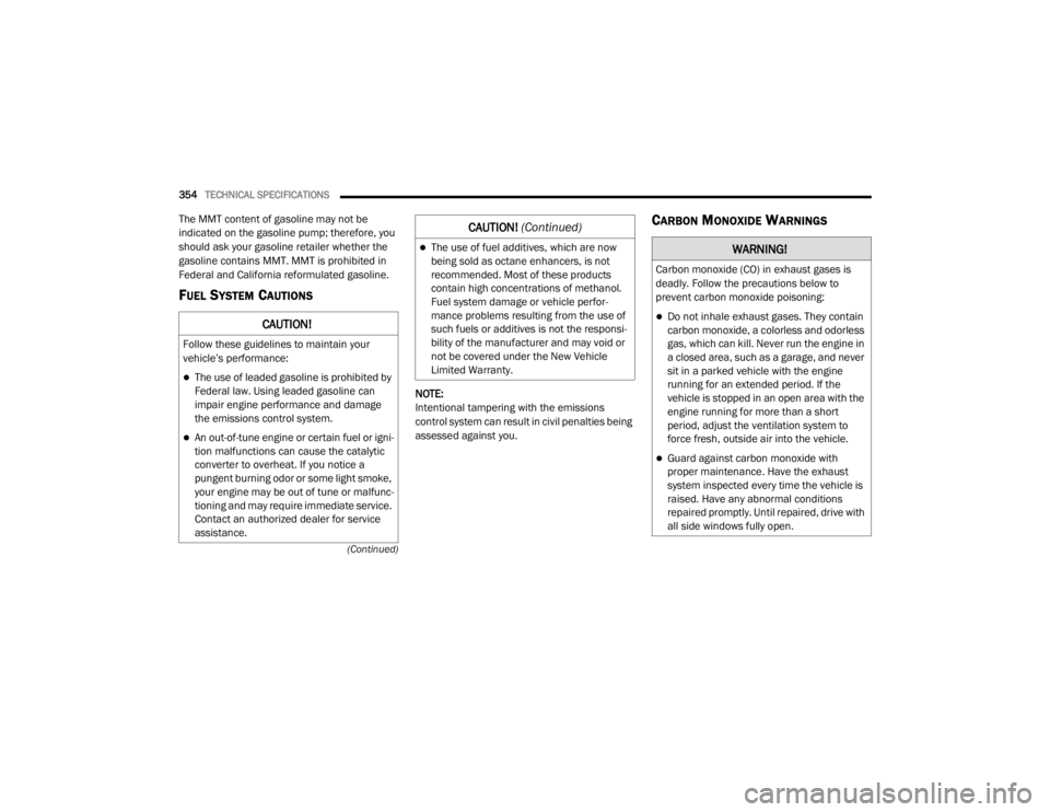
The MMT content of gasoline may not be
indicated on the gasoline pump; therefore, you
should ask your gasoline retailer whether the
gasoline contains MMT. MMT is prohibited in
Federal and California reformulated gasoline.
FUEL SYSTEM CAUTIONS
NOTE:
Intentional tampering with the emissions
control system can result in civil penalties being
assessed against you.
CARBON MONOXIDE WARNINGS
CAUTION!
Follow these guidelines to maintain your
vehicle’s performance:
The use of leaded gasoline is prohibited by
Federal law. Using leaded gasoline can
impair engine performance and damage
the emissions control system.
An out-of-tune engine or certain fuel or igni -
tion malfunctions can cause the catalytic
converter to overheat. If you notice a
pungent burning odor or some light smoke,
your engine may be out of tune or malfunc -
tioning and may require immediate service.
Contact an authorized dealer for service
assistance.
The use of fuel additives, which are now
being sold as octane enhancers, is not
recommended. Most of these products
contain high concentrations of methanol.
Fuel system damage or vehicle perfor -
mance problems resulting from the use of
such fuels or additives is not the responsi -
bility of the manufacturer and may void or
not be covered under the New Vehicle
Limited Warranty.
CAUTION! (Continued)
WARNING!
Carbon monoxide (CO) in exhaust gases is
deadly. Follow the precautions below to
prevent carbon monoxide poisoning:
Do not inhale exhaust gases. They contain
carbon monoxide, a colorless and odorless
gas, which can kill. Never run the engine in
a closed area, such as a garage, and never
sit in a parked vehicle with the engine
running for an extended period. If the
vehicle is stopped in an open area with the
engine running for more than a short
period, adjust the ventilation system to
force fresh, outside air into the vehicle.
Guard against carbon monoxide with
proper maintenance. Have the exhaust
system inspected every time the vehicle is
raised. Have any abnormal conditions
repaired promptly. Until repaired, drive with
all side windows fully open.
20_WD_OM_EN_USC_t.book Page 354
Page 370 of 464
368MULTIMEDIA
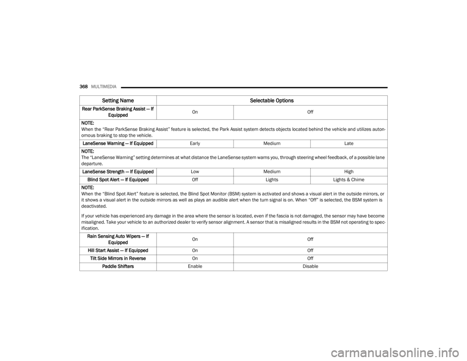
Rear ParkSense Braking Assist — If
Equipped On
Off
NOTE:
When the “Rear ParkSense Braking Assist” feature is selected, the Park Assist system detects objects located behind the vehicle and utilizes auton -
omous braking to stop the vehicle.
LaneSense Warning — If Equipped EarlyMedium Late
NOTE:
The “LaneSense Warning” setting determines at what distance the LaneSense system warns you, through steering wheel feedback, of a possible lane
departure. LaneSense Strength — If Equipped LowMedium High
Blind Spot Alert — If Equipped OffLightsLights & Chime
NOTE:
When the “Blind Spot Alert” feature is selected, the Blind Spot Monitor (BSM) system is activated and shows a visual alert in the outside mirrors, or
it shows a visual alert in the outside mirrors as well as plays an audible alert when the turn signal is on. When “Off” is selected, the BSM system is
deactivated.
If your vehicle has experienced any damage in the area where the sensor is located, even if the fascia is not damaged, the sensor may have become
misaligned. Take your vehicle to an authorized dealer to verify sensor alignment. A sensor that is misaligned results in the BSM not operating to spec -
ification.
Rain Sensing Auto Wipers — If Equipped On
Off
Hill Start Assist — If Equipped On Off
Tilt Side Mirrors in Reverse On Off
Paddle Shifters Enable Disable
Setting Name Selectable Options
20_WD_OM_EN_USC_t.book Page 368