fuel pump DODGE DURANGO 2020 Owners Manual
[x] Cancel search | Manufacturer: DODGE, Model Year: 2020, Model line: DURANGO, Model: DODGE DURANGO 2020Pages: 464, PDF Size: 22.14 MB
Page 98 of 464
96GETTING TO KNOW YOUR INSTRUMENT PANEL
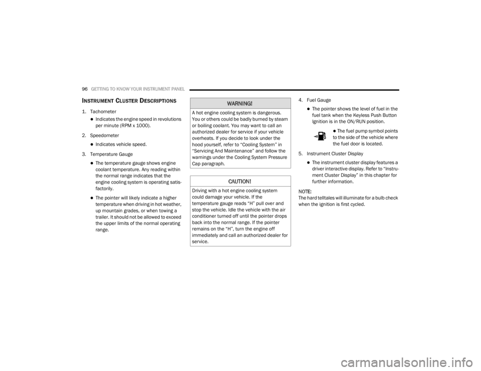
INSTRUMENT CLUSTER DESCRIPTIONS
1. Tachometer
Indicates the engine speed in revolutions
per minute (RPM x 1000).
2. Speedometer
Indicates vehicle speed.
3. Temperature Gauge
The temperature gauge shows engine
coolant temperature. Any reading within
the normal range indicates that the
engine cooling system is operating satis -
factorily.
The pointer will likely indicate a higher
temperature when driving in hot weather,
up mountain grades, or when towing a
trailer. It should not be allowed to exceed
the upper limits of the normal operating
range. 4. Fuel Gauge
The pointer shows the level of fuel in the
fuel tank when the Keyless Push Button
Ignition is in the ON/RUN position.
The fuel pump symbol points
to the side of the vehicle where
the fuel door is located.
5. Instrument Cluster Display
The instrument cluster display features a
driver interactive display. Refer to “Instru -
ment Cluster Display” in this chapter for
further information.
NOTE:
The hard telltales will illuminate for a bulb check
when the ignition is first cycled.
WARNING!
A hot engine cooling system is dangerous.
You or others could be badly burned by steam
or boiling coolant. You may want to call an
authorized dealer for service if your vehicle
overheats. If you decide to look under the
hood yourself, refer to “Cooling System” in
“Servicing And Maintenance” and follow the
warnings under the Cooling System Pressure
Cap paragraph.
CAUTION!
Driving with a hot engine cooling system
could damage your vehicle. If the
temperature gauge reads “H” pull over and
stop the vehicle. Idle the vehicle with the air
conditioner turned off until the pointer drops
back into the normal range. If the pointer
remains on the “H”, turn the engine off
immediately and call an authorized dealer for
service.
20_WD_OM_EN_USC_t.book Page 96
Page 100 of 464
98GETTING TO KNOW YOUR INSTRUMENT PANEL
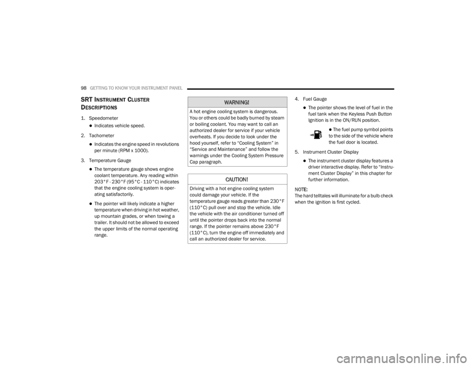
SRT INSTRUMENT CLUSTER
D
ESCRIPTIONS
1. Speedometer
Indicates vehicle speed.
2. Tachometer
Indicates the engine speed in revolutions
per minute (RPM x 1000).
3. Temperature Gauge
The temperature gauge shows engine
coolant temperature. Any reading within
203°F - 230°F (95°C - 110°C) indicates
that the engine cooling system is oper -
ating satisfactorily.
The pointer will likely indicate a higher
temperature when driving in hot weather,
up mountain grades, or when towing a
trailer. It should not be allowed to exceed
the upper limits of the normal operating
range. 4. Fuel Gauge
The pointer shows the level of fuel in the
fuel tank when the Keyless Push Button
Ignition is in the ON/RUN position.
The fuel pump symbol points
to the side of the vehicle where
the fuel door is located.
5. Instrument Cluster Display
The instrument cluster display features a
driver interactive display. Refer to “Instru -
ment Cluster Display” in this chapter for
further information.
NOTE:
The hard telltales will illuminate for a bulb check
when the ignition is first cycled.
WARNING!
A hot engine cooling system is dangerous.
You or others could be badly burned by steam
or boiling coolant. You may want to call an
authorized dealer for service if your vehicle
overheats. If you decide to look under the
hood yourself, refer to “Cooling System” in
“Service and Maintenance” and follow the
warnings under the Cooling System Pressure
Cap paragraph.
CAUTION!
Driving with a hot engine cooling system
could damage your vehicle. If the
temperature gauge reads greater than 230°F
(110°C) pull over and stop the vehicle. Idle
the vehicle with the air conditioner turned off
until the pointer drops back into the normal
range. If the pointer remains above 230°F
(110°C), turn the engine off immediately and
call an authorized dealer for service.
20_WD_OM_EN_USC_t.book Page 98
Page 163 of 464
SAFETY161
(Continued)
Enhanced Accident Response System
In the event of an impact, if the communication
network remains intact, and the power remains
intact, depending on the nature of the event,
the Occupant Restraint Controller (ORC) will
determine whether to have the Enhanced
Accident Response System perform the
following functions:
Cut off fuel to the engine (if equipped)
Cut off battery power to the electric motor (if
equipped)
Flash hazard lights as long as the battery has
power
Turn on the interior lights, which remain on
as long as the battery has power or for
15 minutes from the intervention of the
Enhanced Accident Response System
Unlock the power door locks
Your vehicle may also be designed to perform
any of these other functions in response to the
Enhanced Accident Response System:
Turn off the Fuel Filter Heater, Turn off the
HVAC Blower Motor, Close the HVAC Circula -
tion Door
Cut off battery power to the:
Engine
Electric Motor (if equipped)
Electric power steering
Brake booster
Electric park brake
Automatic transmission gear selector
Horn
Front wiper
Headlamp washer pump
NOTE:
After an accident, remember to cycle the igni -
tion to the STOP (OFF/LOCK) position and
remove the key from the ignition switch to avoid
draining the battery. Carefully check the vehicle
for fuel leaks in the engine compartment and on
the ground near the engine compartment and
fuel tank before resetting the system and
starting the engine. If there are no fuel leaks or
damage to the vehicle electrical devices (e.g.
headlights) after an accident, reset the system
by following the procedure described below. If you have any doubt, contact an authorized
dealer.
Enhanced Accident Response System
Reset Procedure
In order to reset the Enhanced Accident
Response System functions after an event, the
ignition switch must be changed from ignition
START or ON/RUN to ignition OFF. Carefully
check the vehicle for fuel leaks in the engine
compartment and on the ground near the
engine compartment and fuel tank before
resetting the system and starting the engine.
Maintaining Your Air Bag System
WARNING!
Modifications to any part of the air bag
system could cause it to fail when you need
it. You could be injured if the air bag system
is not there to protect you. Do not modify
the components or wiring, including adding
any kind of badges or stickers to the
steering wheel hub trim cover or the upper
passenger side of the instrument panel. Do
not modify the front bumper, vehicle body
structure, or add aftermarket side steps or
running boards.
4
20_WD_OM_EN_USC_t.book Page 161
Page 241 of 464
STARTING AND OPERATING239
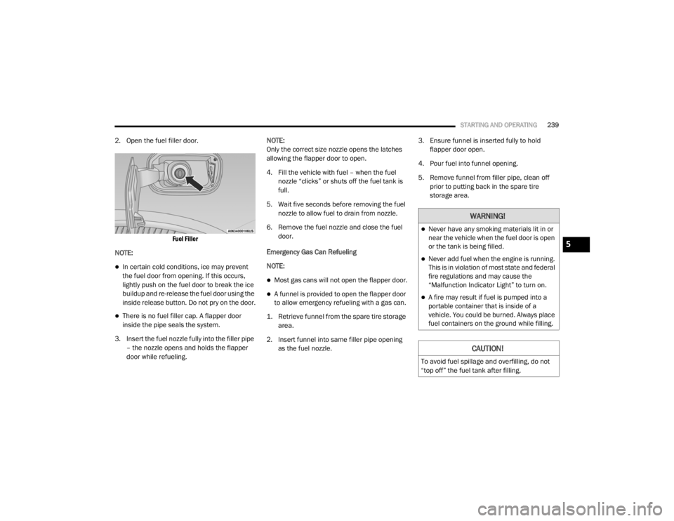
2. Open the fuel filler door.
Fuel Filler
NOTE:
In certain cold conditions, ice may prevent
the fuel door from opening. If this occurs,
lightly push on the fuel door to break the ice
buildup and re-release the fuel door using the
inside release button. Do not pry on the door.
There is no fuel filler cap. A flapper door
inside the pipe seals the system.
3. Insert the fuel nozzle fully into the filler pipe – the nozzle opens and holds the flapper
door while refueling. NOTE:
Only the correct size nozzle opens the latches
allowing the flapper door to open.
4. Fill the vehicle with fuel – when the fuel
nozzle “clicks” or shuts off the fuel tank is
full.
5. Wait five seconds before removing the fuel nozzle to allow fuel to drain from nozzle.
6. Remove the fuel nozzle and close the fuel door.
Emergency Gas Can Refueling
NOTE:
Most gas cans will not open the flapper door.
A funnel is provided to open the flapper door
to allow emergency refueling with a gas can.
1. Retrieve funnel from the spare tire storage area.
2. Insert funnel into same filler pipe opening as the fuel nozzle. 3. Ensure funnel is inserted fully to hold
flapper door open.
4. Pour fuel into funnel opening.
5. Remove funnel from filler pipe, clean off prior to putting back in the spare tire
storage area.
WARNING!
Never have any smoking materials lit in or
near the vehicle when the fuel door is open
or the tank is being filled.
Never add fuel when the engine is running.
This is in violation of most state and federal
fire regulations and may cause the
“Malfunction Indicator Light” to turn on.
A fire may result if fuel is pumped into a
portable container that is inside of a
vehicle. You could be burned. Always place
fuel containers on the ground while filling.
CAUTION!
To avoid fuel spillage and overfilling, do not
“top off” the fuel tank after filling.
5
20_WD_OM_EN_USC_t.book Page 239
Page 273 of 464
IN CASE OF EMERGENCY271
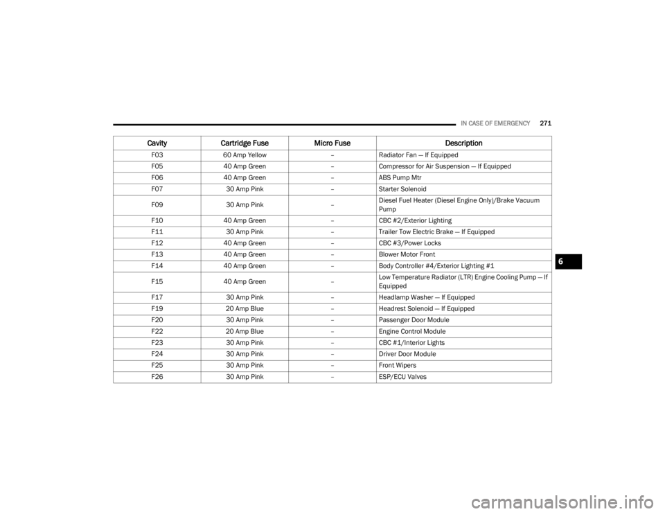
CavityCartridge Fuse Micro Fuse Description
F0360 Amp Yellow –Radiator Fan — If Equipped
F05 40 Amp Green –Compressor for Air Suspension — If Equipped
F06 40 Amp Green –ABS Pump Mtr
F07 30 Amp Pink –Starter Solenoid
F09 30 Amp Pink –Diesel Fuel Heater (Diesel Engine Only)/Brake Vacuum
Pump
F10 40 Amp Green –CBC #2/Exterior Lighting
F11 30 Amp Pink –Trailer Tow Electric Brake — If Equipped
F12 40 Amp Green –CBC #3/Power Locks
F13 40 Amp Green –Blower Motor Front
F14 40 Amp Green –Body Controller #4/Exterior Lighting #1
F15 40 Amp Green –Low Temperature Radiator (LTR) Engine Cooling Pump — If
Equipped
F17 30 Amp Pink –Headlamp Washer — If Equipped
F19 20 Amp Blue –Headrest Solenoid — If Equipped
F20 30 Amp Pink –Passenger Door Module
F22 20 Amp Blue –Engine Control Module
F23 30 Amp Pink –CBC #1/Interior Lights
F24 30 Amp Pink –Driver Door Module
F25 30 Amp Pink –Front Wipers
F26 30 Amp Pink –ESP/ECU Valves
6
20_WD_OM_EN_USC_t.book Page 271
Page 275 of 464
IN CASE OF EMERGENCY273
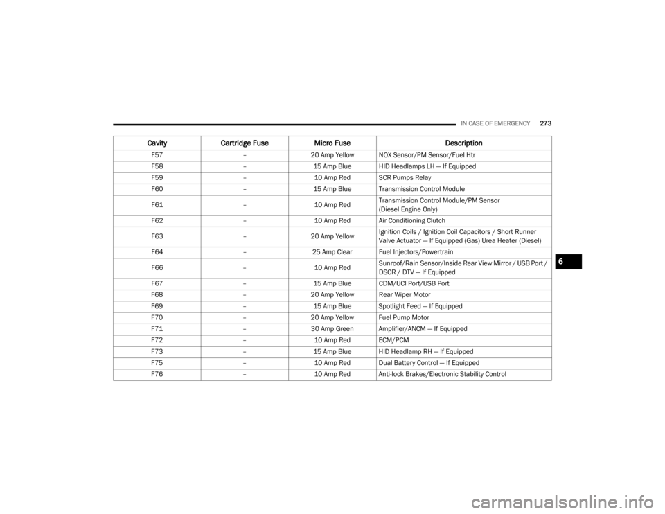
F57 –20 Amp Yellow NOX Sensor/PM Sensor/Fuel Htr
F58 –15 Amp Blue HID Headlamps LH — If Equipped
F59 –10 Amp Red SCR Pumps Relay
F60 –15 Amp Blue Transmission Control Module
F61 –10 Amp RedTransmission Control Module/PM Sensor
(Diesel Engine Only)
F62 –10 Amp Red Air Conditioning Clutch
F63 –20 Amp Yellow Ignition Coils / Ignition Coil Capacitors / Short Runner
Valve Actuator — If Equipped (Gas) Urea Heater (Diesel)
F64 –25 Amp Clear Fuel Injectors/Powertrain
F66 –10 Amp RedSunroof/Rain Sensor/Inside Rear View Mirror / USB Port /
DSCR / DTV — If Equipped
F67 –15 Amp Blue CDM/UCI Port/USB Port
F68 –20 Amp Yellow Rear Wiper Motor
F69 –15 Amp Blue Spotlight Feed — If Equipped
F70 –20 Amp Yellow Fuel Pump Motor
F71 –30 Amp Green Amplifier/ANCM — If Equipped
F72 –10 Amp Red ECM/PCM
F73 –15 Amp Blue HID Headlamp RH — If Equipped
F75 –10 Amp Red Dual Battery Control — If Equipped
F76 –10 Amp Red Anti-lock Brakes/Electronic Stability Control
CavityCartridge Fuse Micro Fuse Description
6
20_WD_OM_EN_USC_t.book Page 273
Page 355 of 464
TECHNICAL SPECIFICATIONS353
When available, the usage of TOP TIER
Detergent Gasoline is recommended. Visit
www.toptiergas.com for a list of TOP TIER
Detergent Gasoline Retailers.
Indiscriminate use of fuel system cleaning
agents should be avoided. Many of these
materials intended for gum and varnish
removal may contain active solvents or similar
ingredients. These can harm fuel system gasket
and diaphragm materials.
GASOLINE/OXYGENATE BLENDS
Some fuel suppliers blend unleaded gasoline
with oxygenates such as ethanol. Problems that result from using gasoline
containing more than 15% ethanol (E-15) or
gasoline containing methanol are not the
responsibility of the manufacturer and may void
or not be covered under New Vehicle Limited
Warranty.
DO NOT USE E-85 IN NON-FLEX FUEL
V
EHICLES
Non-Flex Fuel Vehicles (FFV) are compatible
with gasoline containing up to 15% ethanol
(E-15). Use of gasoline with higher ethanol
content may void the New Vehicle Limited
Warranty.
If a Non-FFV vehicle is inadvertently fueled with
E-85 fuel, the engine will have some or all of
these symptoms:
Operate in a lean mode.
OBD II Malfunction Indicator Light on.
Poor engine performance.
Poor cold start and cold drivability.
Increased risk for fuel system component
corrosion.
CNG AND LP FUEL SYSTEM
M
ODIFICATIONS
Modifications that allow the engine to run on
Compressed Natural Gas (CNG) or Liquid
Propane (LP) may result in damage to the
engine, emissions, and fuel system
components. Problems that result from running
CNG or LP are not the responsibility of the
manufacturer and may void or not be covered
under the New Vehicle Limited Warranty.
MMT IN GASOLINE
Methylcyclopentadienyl Manganese Tricarbonyl
(MMT) is a manganese-containing metallic
additive that is blended into some gasoline to
increase octane. Gasoline blended with MMT
provides no performance advantage beyond
gasoline of the same octane number without
MMT. Gasoline blended with MMT reduces
spark plug life and reduces emissions system
performance in some vehicles. The
manufacturer recommends that gasoline
without MMT be used in your vehicle.
CAUTION!
DO NOT use E-85, gasoline containing
methanol, or gasoline containing more than
15% ethanol (E-15). Use of these blends may
result in starting and drivability problems,
damage critical fuel system components,
cause emissions to exceed the applicable
standard, and/or cause the Malfunction
Indicator Light to illuminate. Please observe
pump labels as they should clearly
communicate if a fuel contains greater than
15% ethanol (E-15).
8
20_WD_OM_EN_USC_t.book Page 353
Page 356 of 464
354TECHNICAL SPECIFICATIONS
(Continued)
The MMT content of gasoline may not be
indicated on the gasoline pump; therefore, you
should ask your gasoline retailer whether the
gasoline contains MMT. MMT is prohibited in
Federal and California reformulated gasoline.
FUEL SYSTEM CAUTIONS
NOTE:
Intentional tampering with the emissions
control system can result in civil penalties being
assessed against you.
CARBON MONOXIDE WARNINGS
CAUTION!
Follow these guidelines to maintain your
vehicle’s performance:
The use of leaded gasoline is prohibited by
Federal law. Using leaded gasoline can
impair engine performance and damage
the emissions control system.
An out-of-tune engine or certain fuel or igni -
tion malfunctions can cause the catalytic
converter to overheat. If you notice a
pungent burning odor or some light smoke,
your engine may be out of tune or malfunc -
tioning and may require immediate service.
Contact an authorized dealer for service
assistance.
The use of fuel additives, which are now
being sold as octane enhancers, is not
recommended. Most of these products
contain high concentrations of methanol.
Fuel system damage or vehicle perfor -
mance problems resulting from the use of
such fuels or additives is not the responsi -
bility of the manufacturer and may void or
not be covered under the New Vehicle
Limited Warranty.
CAUTION! (Continued)
WARNING!
Carbon monoxide (CO) in exhaust gases is
deadly. Follow the precautions below to
prevent carbon monoxide poisoning:
Do not inhale exhaust gases. They contain
carbon monoxide, a colorless and odorless
gas, which can kill. Never run the engine in
a closed area, such as a garage, and never
sit in a parked vehicle with the engine
running for an extended period. If the
vehicle is stopped in an open area with the
engine running for more than a short
period, adjust the ventilation system to
force fresh, outside air into the vehicle.
Guard against carbon monoxide with
proper maintenance. Have the exhaust
system inspected every time the vehicle is
raised. Have any abnormal conditions
repaired promptly. Until repaired, drive with
all side windows fully open.
20_WD_OM_EN_USC_t.book Page 354