fuse DODGE DURANGO 2020 Owners Manual
[x] Cancel search | Manufacturer: DODGE, Model Year: 2020, Model line: DURANGO, Model: DODGE DURANGO 2020Pages: 464, PDF Size: 22.14 MB
Page 8 of 464
6
RECREATIONAL TOWING (BEHIND
MOTORHOME, ETC.) ......................................... 253 Towing This Vehicle Behind Another
Vehicle .......................................................253 Recreational Towing — Rear-Wheel
Drive Models ..............................................254 Recreational Towing — All Wheel Drive
Models (Single-Speed Transfer Case) ......254 Recreational Towing — All-Wheel Drive
Models (Two-Speed Transfer Case) ..........254
DRIVING TIPS ..................................................... 257
On-Road Driving Tips .................................257
Off-Road Driving Tips .................................258
IN CASE OF EMERGENCY
HAZARD WARNING FLASHERS ....................... 261
ASSIST AND SOS MIRROR — IF EQUIPPED.... 261General Information ..................................265
BULB REPLACEMENT ....................................... 266
Replacement Bulbs .................................266
Bulb Replacement ....................................268
FUSES .................................................................. 269
General Information ..................................270Underhood Fuses.......................................270 JACKING AND TIRE CHANGING .......................275
Run Flat Tires ............................................. 276
Jack Location ............................................. 276
Spare Tire Stowage ................................... 277
Spare Tire Removal ................................... 277
Preparations For Jacking .......................... 279Jacking Instructions .................................. 279Road Tire Installation ................................ 283
JUMP STARTING ................................................ 283
Preparations For Jump Start ..................... 284Jump Starting Procedure .......................... 285
REFUELING IN EMERGENCY –
IF EQUIPPED ...................................................... 286
IF YOUR ENGINE OVERHEATS .........................287
MANUAL PARK RELEASE .................................. 287
FREEING A STUCK VEHICLE .............................289
TOWING A DISABLED VEHICLE .......................290 Rear Wheel Drive Models.......................... 292All Wheel Drive Models.............................. 292
TOWING A DISABLED SRT VEHICLE ................293
ENHANCED ACCIDENT RESPONSE SYSTEM
(EARS) .................................................................293
EVENT DATA RECORDER (EDR) .......................293
SERVICING AND MAINTENANCE
SCHEDULED SERVICING — NON-SRT .............. 294
Maintenance Plan — Non-SRT .................. 294Heavy Duty Use Of The Vehicle................. 298
SCHEDULED SERVICING – SRT ....................... 298
Maintenance Plan — SRT .......................... 300
ENGINE COMPARTMENT .................................. 304
3.6L Engine ................................................ 304
5.7L Engine ................................................ 305
6.4L Engine ................................................ 306
Checking Oil Level ..................................... 307
Adding Washer Fluid ................................ 307
Maintenance-Free Battery ....................... 307Pressure Washing...................................... 308
DEALER SERVICE .............................................. 308
Engine Oil .................................................. 308
Engine Oil Filter ......................................... 311Engine Air Cleaner Filter............................ 311Air Conditioner Maintenance .................... 313Accessory Drive Belt Inspection ............... 315Body Lubrication ....................................... 316
Windshield Wiper Blades ......................... 316
Exhaust System ........................................ 320
Cooling System .......................................... 321
Brake System ............................................ 325Automatic Transmission............................ 326Front/Rear Axle Fluid ............................... 327Transfer Case ............................................ 327
20_WD_OM_EN_USC_t.book Page 6
Page 89 of 464
GETTING TO KNOW YOUR VEHICLE87
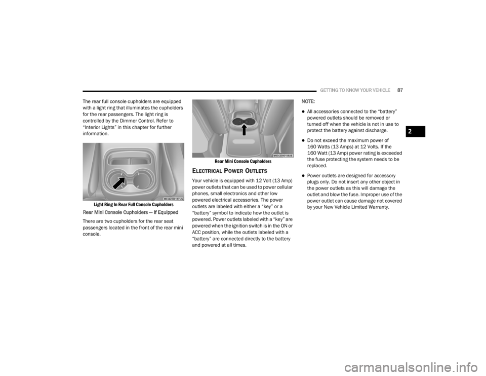
The rear full console cupholders are equipped
with a light ring that illuminates the cupholders
for the rear passengers. The light ring is
controlled by the Dimmer Control. Refer to
“Interior Lights” in this chapter for further
information.
Light Ring In Rear Full Console Cupholders
Rear Mini Console Cupholders — If Equipped
There are two cupholders for the rear seat
passengers located in the front of the rear mini
console.
Rear Mini Console Cupholders
ELECTRICAL POWER OUTLETS
Your vehicle is equipped with 12 Volt (13 Amp)
power outlets that can be used to power cellular
phones, small electronics and other low
powered electrical accessories. The power
outlets are labeled with either a “key” or a
“battery” symbol to indicate how the outlet is
powered. Power outlets labeled with a “key” are
powered when the ignition switch is in the ON or
ACC position, while the outlets labeled with a
“battery” are connected directly to the battery
and powered at all times.NOTE:
All accessories connected to the “battery”
powered outlets should be removed or
turned off when the vehicle is not in use to
protect the battery against discharge.
Do not exceed the maximum power of
160 Watts (13 Amps) at 12 Volts. If the
160 Watt (13 Amp) power rating is exceeded
the fuse protecting the system needs to be
replaced.
Power outlets are designed for accessory
plugs only. Do not insert any other object in
the power outlets as this will damage the
outlet and blow the fuse. Improper use of the
power outlet can cause damage not covered
by your New Vehicle Limited Warranty.
2
20_WD_OM_EN_USC_t.book Page 87
Page 91 of 464
GETTING TO KNOW YOUR VEHICLE89
(Continued)
NOTE:
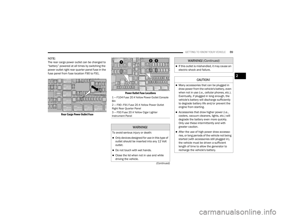
The rear cargo power outlet can be changed to
“battery” powered at all times by switching the
power outlet right rear quarter panel fuse in the
fuse panel from fuse location F90 to F91.
Rear Cargo Power Outlet Fuse Power Outlet Fuse Locations
1 — F104 Fuse 20 A Yellow Power Outlet Console
Bin
2 — F90–F91 Fuse 20 A Yellow Power Outlet
Right Rear Quarter Panel
3 — F93 Fuse 20 A Yellow Cigar Lighter
Instrument Panel
WARNING!
To avoid serious injury or death:
Only devices designed for use in this type of
outlet should be inserted into any 12 Volt
outlet.
Do not touch with wet hands.
Close the lid when not in use and while
driving the vehicle.
If this outlet is mishandled, it may cause an
electric shock and failure.
CAUTION!
Many accessories that can be plugged in
draw power from the vehicle's battery, even
when not in use (i.e., cellular phones, etc.).
Eventually, if plugged in long enough, the
vehicle's battery will discharge sufficiently
to degrade battery life and/or prevent the
engine from starting.
Accessories that draw higher power (i.e.,
coolers, vacuum cleaners, lights, etc.) will
degrade the battery even more quickly.
Only use these intermittently and with
greater caution.
After the use of high power draw accesso
-
ries, or long periods of the vehicle not being
started (with accessories still plugged in),
the vehicle must be driven a sufficient
length of time to allow the generator to
recharge the vehicle's battery.
WARNING! (Continued)
2
20_WD_OM_EN_USC_t.book Page 89
Page 271 of 464
IN CASE OF EMERGENCY269
(Continued)
Front Turn Signal
1. Open the hood.
2. Turn the turn signal bulb a quarter turn counterclockwise to remove from housing.
3. Disconnect the electrical connector and replace the bulb.
Front Fog Lamps
1. Reach through the cutout in the splash shield and rotate the bulb’s electrical
connector a quarter turn counterclockwise
and remove it from the fog lamp housing.
2. Remove the bulb from the connector and install the replacement bulb.
3. Install the bulb and connector assembly into the fog lamp housing and rotate the
connector a quarter turn clockwise to lock it
in place.
Rear Tail, Stop And Turn Signal Lamps
The rear tail, stop, and turn signal lamps are
LED. See an authorized dealer for replacement.
Rear Liftgate Mounted Back-up Lamps
1. Raise the liftgate.
2. Use a fiber stick or flat blade screw driver to pry the lower trim from the liftgate.
3. Back-up lamps are now visible. Rotate socket(s) counterclockwise.
4. Remove/replace bulb(s).
5. Reinstall the socket(s). 6. Reverse process to reinstall the liftgate
trim.
Center High Mounted Stop Lamp (CHMSL)
The Center High Mounted Stop Lamp is an LED
assembly. See an authorized dealer for
replacement.
Rear License Lamp
The rear license lamps are LEDs. See an
authorized dealer for service.
FUSES
CAUTION!
Do not touch the new bulb with your fingers.
Oil contamination will severely shorten bulb
life. If the bulb comes in contact with an oily
surface, clean the bulb with rubbing alcohol.
CAUTION!
Do not touch the new bulb with your fingers.
Oil contamination will severely shorten bulb
life. If the bulb comes in contact with any
oily surface, clean the bulb with rubbing
alcohol.
Always use the correct bulb size and type
for replacement. An incorrect bulb size or
type may overheat and cause damage to
the lamp, the socket or the lamp wiring.
WARNING!
When replacing a blown fuse, always use
an appropriate replacement fuse with the
same amp rating as the original fuse. Never
replace a fuse with another fuse of higher
amp rating. Never replace a blown fuse with
metal wires or any other material. Do not
place a fuse inside a circuit breaker cavity
or vice versa. Failure to use proper fuses
may result in serious personal injury, fire
and/or property damage.
Before replacing a fuse, make sure that the
ignition is off and that all the other services
are switched off and/or disengaged.
6
20_WD_OM_EN_USC_t.book Page 269
Page 272 of 464
270IN CASE OF EMERGENCY
GENERAL INFORMATION
The fuses protect electrical systems against
excessive current.
When a device does not work, you must check
the fuse element inside the blade fuse for a
break/melt.
Also, please be aware that when using power
outlets for extended periods of time with the
engine off may result in vehicle battery
discharge.
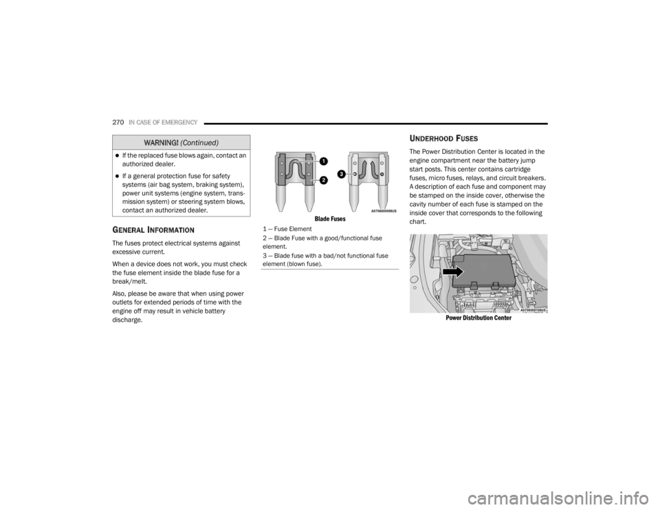
Blade Fuses
UNDERHOOD FUSES
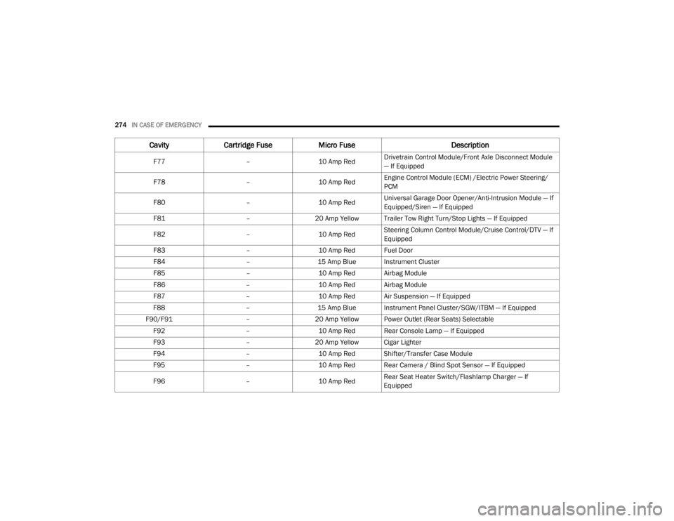
The Power Distribution Center is located in the
engine compartment near the battery jump
start posts. This center contains cartridge
fuses, micro fuses, relays, and circuit breakers.
A description of each fuse and component may
be stamped on the inside cover, otherwise the
cavity number of each fuse is stamped on the
inside cover that corresponds to the following
chart.
Power Distribution Center
If the replaced fuse blows again, contact an
authorized dealer.
If a general protection fuse for safety
systems (air bag system, braking system),
power unit systems (engine system, trans -
mission system) or steering system blows,
contact an authorized dealer.
WARNING! (Continued)
1 — Fuse Element
2 — Blade Fuse with a good/functional fuse
element.
3 — Blade fuse with a bad/not functional fuse
element (blown fuse).
20_WD_OM_EN_USC_t.book Page 270
Page 273 of 464
IN CASE OF EMERGENCY271
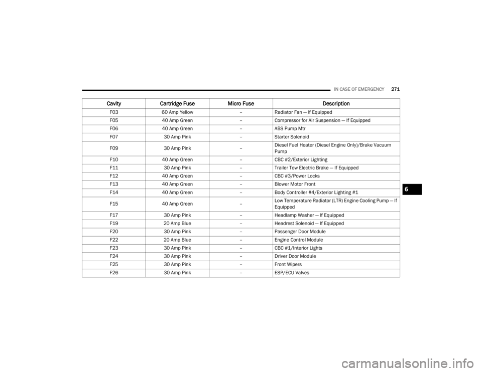
CavityCartridge Fuse Micro Fuse Description
F0360 Amp Yellow –Radiator Fan — If Equipped
F05 40 Amp Green –Compressor for Air Suspension — If Equipped
F06 40 Amp Green –ABS Pump Mtr
F07 30 Amp Pink –Starter Solenoid
F09 30 Amp Pink –Diesel Fuel Heater (Diesel Engine Only)/Brake Vacuum
Pump
F10 40 Amp Green –CBC #2/Exterior Lighting
F11 30 Amp Pink –Trailer Tow Electric Brake — If Equipped
F12 40 Amp Green –CBC #3/Power Locks
F13 40 Amp Green –Blower Motor Front
F14 40 Amp Green –Body Controller #4/Exterior Lighting #1
F15 40 Amp Green –Low Temperature Radiator (LTR) Engine Cooling Pump — If
Equipped
F17 30 Amp Pink –Headlamp Washer — If Equipped
F19 20 Amp Blue –Headrest Solenoid — If Equipped
F20 30 Amp Pink –Passenger Door Module
F22 20 Amp Blue –Engine Control Module
F23 30 Amp Pink –CBC #1/Interior Lights
F24 30 Amp Pink –Driver Door Module
F25 30 Amp Pink –Front Wipers
F26 30 Amp Pink –ESP/ECU Valves
6
20_WD_OM_EN_USC_t.book Page 271
Page 274 of 464
272IN CASE OF EMERGENCY
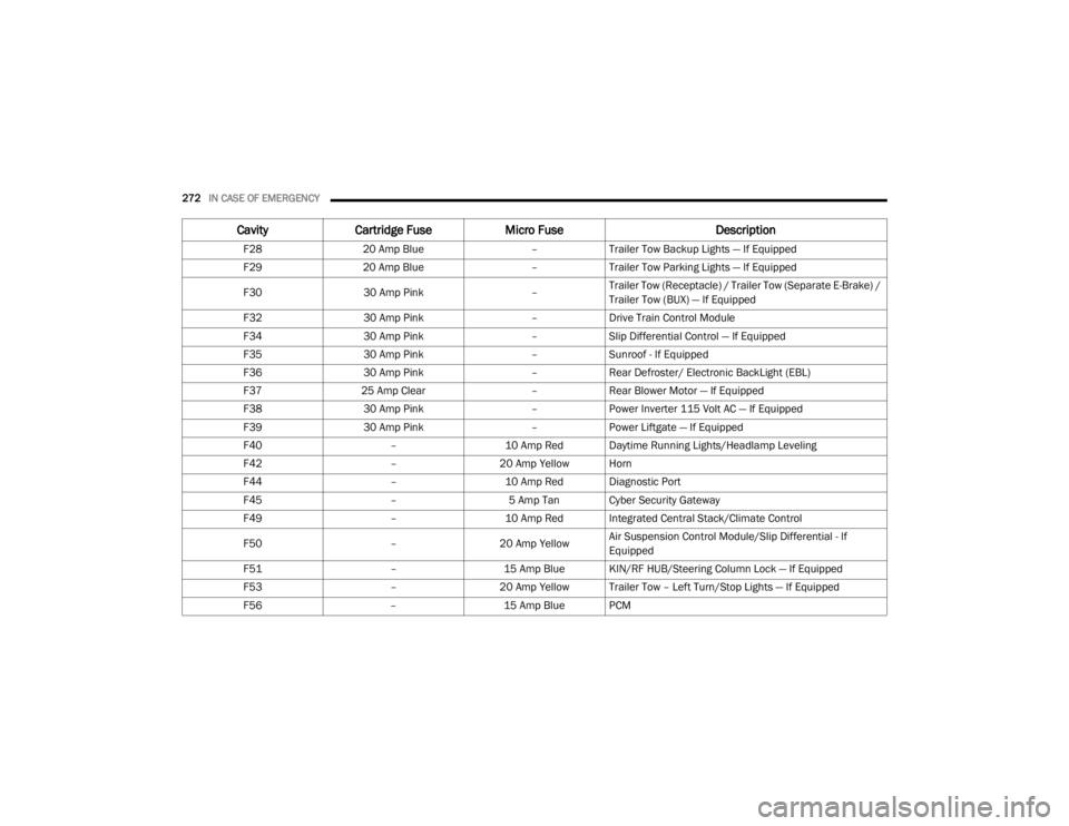
F2820 Amp Blue –Trailer Tow Backup Lights — If Equipped
F29 20 Amp Blue –Trailer Tow Parking Lights — If Equipped
F30 30 Amp Pink –Trailer Tow (Receptacle) / Trailer Tow (Separate E-Brake) /
Trailer Tow (BUX) — If Equipped
F32 30 Amp Pink –Drive Train Control Module
F34 30 Amp Pink –Slip Differential Control — If Equipped
F35 30 Amp Pink –Sunroof - If Equipped
F36 30 Amp Pink –Rear Defroster/ Electronic BackLight (EBL)
F37 25 Amp Clear –Rear Blower Motor — If Equipped
F38 30 Amp Pink –Power Inverter 115 Volt AC — If Equipped
F39 30 Amp Pink –Power Liftgate — If Equipped
F40 –10 Amp Red Daytime Running Lights/Headlamp Leveling
F42 –20 Amp Yellow Horn
F44 –10 Amp Red Diagnostic Port
F45 –5 Amp Tan Cyber Security Gateway
F49 –10 Amp Red Integrated Central Stack/Climate Control
F50 –20 Amp Yellow Air Suspension Control Module/Slip Differential - If
Equipped
F51 –15 Amp Blue KIN/RF HUB/Steering Column Lock — If Equipped
F53 –20 Amp Yellow Trailer Tow – Left Turn/Stop Lights — If Equipped
F56 –15 Amp Blue PCM
CavityCartridge Fuse Micro Fuse Description
20_WD_OM_EN_USC_t.book Page 272
Page 275 of 464
IN CASE OF EMERGENCY273
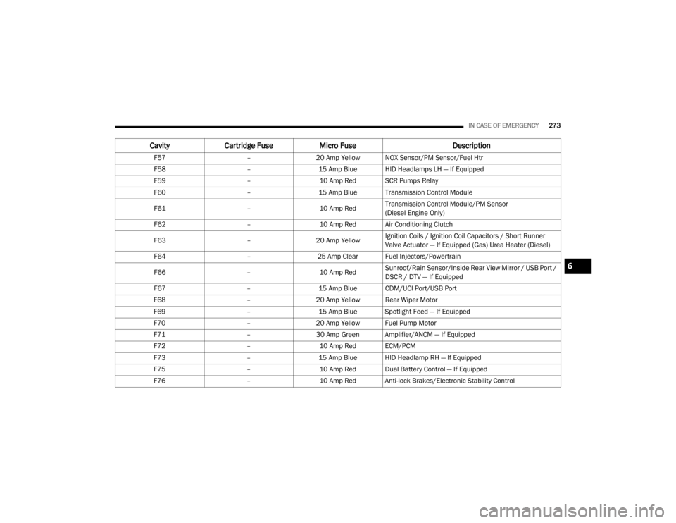
F57 –20 Amp Yellow NOX Sensor/PM Sensor/Fuel Htr
F58 –15 Amp Blue HID Headlamps LH — If Equipped
F59 –10 Amp Red SCR Pumps Relay
F60 –15 Amp Blue Transmission Control Module
F61 –10 Amp RedTransmission Control Module/PM Sensor
(Diesel Engine Only)
F62 –10 Amp Red Air Conditioning Clutch
F63 –20 Amp Yellow Ignition Coils / Ignition Coil Capacitors / Short Runner
Valve Actuator — If Equipped (Gas) Urea Heater (Diesel)
F64 –25 Amp Clear Fuel Injectors/Powertrain
F66 –10 Amp RedSunroof/Rain Sensor/Inside Rear View Mirror / USB Port /
DSCR / DTV — If Equipped
F67 –15 Amp Blue CDM/UCI Port/USB Port
F68 –20 Amp Yellow Rear Wiper Motor
F69 –15 Amp Blue Spotlight Feed — If Equipped
F70 –20 Amp Yellow Fuel Pump Motor
F71 –30 Amp Green Amplifier/ANCM — If Equipped
F72 –10 Amp Red ECM/PCM
F73 –15 Amp Blue HID Headlamp RH — If Equipped
F75 –10 Amp Red Dual Battery Control — If Equipped
F76 –10 Amp Red Anti-lock Brakes/Electronic Stability Control
CavityCartridge Fuse Micro Fuse Description
6
20_WD_OM_EN_USC_t.book Page 273
Page 276 of 464
274IN CASE OF EMERGENCY
F77 –10 Amp RedDrivetrain Control Module/Front Axle Disconnect Module
— If Equipped
F78 –10 Amp RedEngine Control Module (ECM) /Electric Power Steering/
PCM
F80 –10 Amp RedUniversal Garage Door Opener/Anti-Intrusion Module — If
Equipped/Siren — If Equipped
F81 –20 Amp Yellow Trailer Tow Right Turn/Stop Lights — If Equipped
F82 –10 Amp RedSteering Column Control Module/Cruise Control/DTV — If
Equipped
F83 –10 Amp Red Fuel Door
F84 –15 Amp Blue Instrument Cluster
F85 –10 Amp Red Airbag Module
F86 –10 Amp Red Airbag Module
F87 –10 Amp Red Air Suspension — If Equipped
F88 –15 Amp Blue Instrument Panel Cluster/SGW/ITBM — If Equipped
F90/F91 –20 Amp Yellow Power Outlet (Rear Seats) Selectable
F92 –10 Amp Red Rear Console Lamp — If Equipped
F93 –20 Amp Yellow Cigar Lighter
F94 –10 Amp Red Shifter/Transfer Case Module
F95 –10 Amp Red Rear Camera / Blind Spot Sensor — If Equipped
F96 –10 Amp RedRear Seat Heater Switch/Flashlamp Charger — If
Equipped
Cavity
Cartridge Fuse Micro Fuse Description
20_WD_OM_EN_USC_t.book Page 274
Page 277 of 464
IN CASE OF EMERGENCY275
(Continued)
(Continued)
JACKING AND TIRE CHANGING
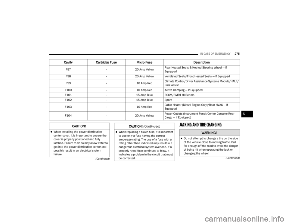
F97 –20 Amp Yellow Rear Heated Seats & Heated Steering Wheel — If
Equipped
F98 –20 Amp Yellow Ventilated Seats/Front Heated Seats — If Equipped
F99 –10 Amp RedClimate Control/Driver Assistance Systems Module/HALF/
Park Assist
F100 –10 Amp Red Active Damping — If Equipped
F101 –15 Amp Blue ECCM/SMRT HI-Beams
F102 –15 Amp Blue Spare
F103 –10 Amp RedCabin Heater (Diesel Engine Only)/Rear HVAC — If
Equipped
F104 –20 Amp Yellow Power Outlets (Instrument Panel/Center Console/Rear
Cargo — If Equipped)
Cavity
Cartridge Fuse Micro Fuse Description
CAUTION!
When installing the power distribution
center cover, it is important to ensure the
cover is properly positioned and fully
latched. Failure to do so may allow water to
get into the power distribution center and
possibly result in an electrical system
failure.When replacing a blown fuse, it is important
to use only a fuse having the correct
amperage rating. The use of a fuse with a
rating other than indicated may result in a
dangerous electrical system overload. If a
properly rated fuse continues to blow, it
indicates a problem in the circuit that must
be corrected.
CAUTION! (Continued)
WARNING!
Do not attempt to change a tire on the side
of the vehicle close to moving traffic. Pull
far enough off the road to avoid the danger
of being hit when operating the jack or
changing the wheel.
6
20_WD_OM_EN_USC_t.book Page 275