low oil pressure DODGE DURANGO 2020 Owners Manual
[x] Cancel search | Manufacturer: DODGE, Model Year: 2020, Model line: DURANGO, Model: DODGE DURANGO 2020Pages: 464, PDF Size: 22.14 MB
Page 98 of 464
96GETTING TO KNOW YOUR INSTRUMENT PANEL
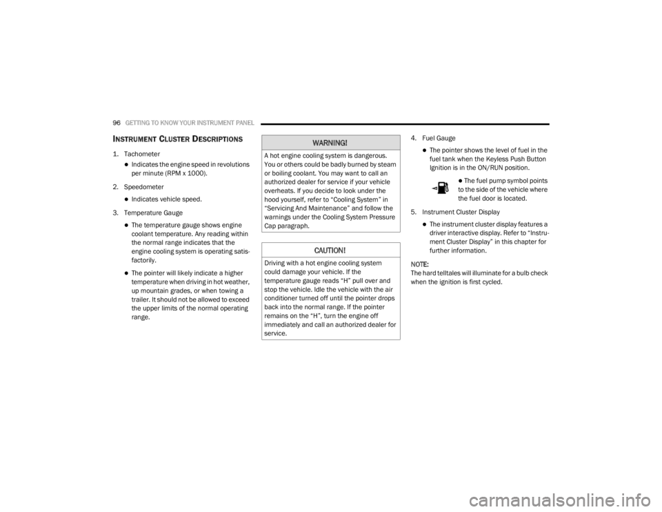
INSTRUMENT CLUSTER DESCRIPTIONS
1. Tachometer
Indicates the engine speed in revolutions
per minute (RPM x 1000).
2. Speedometer
Indicates vehicle speed.
3. Temperature Gauge
The temperature gauge shows engine
coolant temperature. Any reading within
the normal range indicates that the
engine cooling system is operating satis -
factorily.
The pointer will likely indicate a higher
temperature when driving in hot weather,
up mountain grades, or when towing a
trailer. It should not be allowed to exceed
the upper limits of the normal operating
range. 4. Fuel Gauge
The pointer shows the level of fuel in the
fuel tank when the Keyless Push Button
Ignition is in the ON/RUN position.
The fuel pump symbol points
to the side of the vehicle where
the fuel door is located.
5. Instrument Cluster Display
The instrument cluster display features a
driver interactive display. Refer to “Instru -
ment Cluster Display” in this chapter for
further information.
NOTE:
The hard telltales will illuminate for a bulb check
when the ignition is first cycled.
WARNING!
A hot engine cooling system is dangerous.
You or others could be badly burned by steam
or boiling coolant. You may want to call an
authorized dealer for service if your vehicle
overheats. If you decide to look under the
hood yourself, refer to “Cooling System” in
“Servicing And Maintenance” and follow the
warnings under the Cooling System Pressure
Cap paragraph.
CAUTION!
Driving with a hot engine cooling system
could damage your vehicle. If the
temperature gauge reads “H” pull over and
stop the vehicle. Idle the vehicle with the air
conditioner turned off until the pointer drops
back into the normal range. If the pointer
remains on the “H”, turn the engine off
immediately and call an authorized dealer for
service.
20_WD_OM_EN_USC_t.book Page 96
Page 100 of 464
98GETTING TO KNOW YOUR INSTRUMENT PANEL
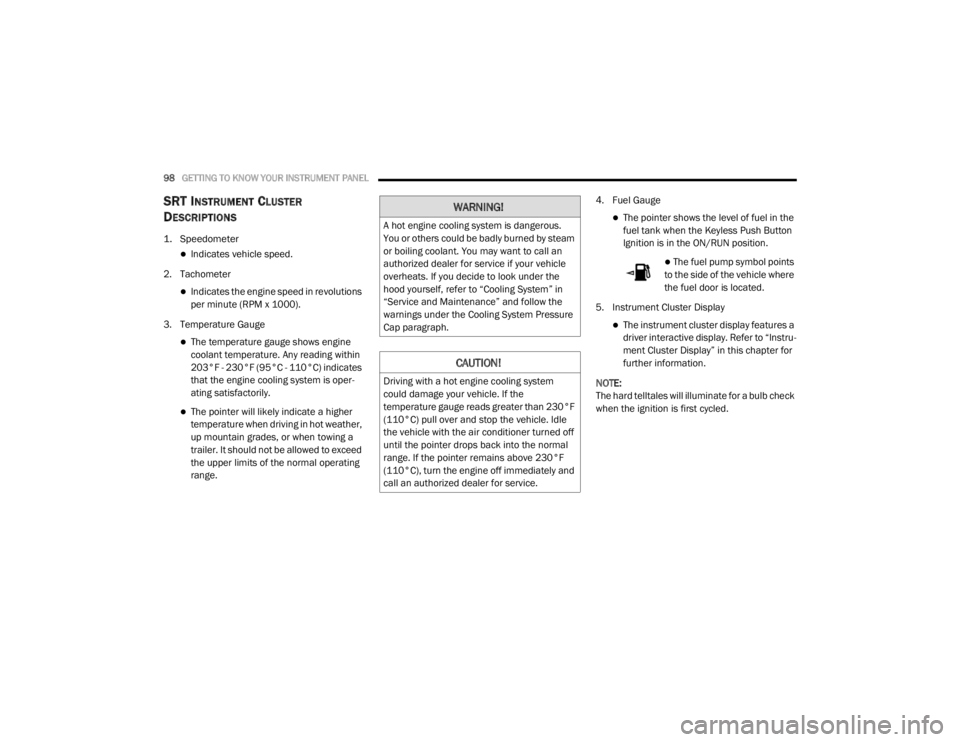
SRT INSTRUMENT CLUSTER
D
ESCRIPTIONS
1. Speedometer
Indicates vehicle speed.
2. Tachometer
Indicates the engine speed in revolutions
per minute (RPM x 1000).
3. Temperature Gauge
The temperature gauge shows engine
coolant temperature. Any reading within
203°F - 230°F (95°C - 110°C) indicates
that the engine cooling system is oper -
ating satisfactorily.
The pointer will likely indicate a higher
temperature when driving in hot weather,
up mountain grades, or when towing a
trailer. It should not be allowed to exceed
the upper limits of the normal operating
range. 4. Fuel Gauge
The pointer shows the level of fuel in the
fuel tank when the Keyless Push Button
Ignition is in the ON/RUN position.
The fuel pump symbol points
to the side of the vehicle where
the fuel door is located.
5. Instrument Cluster Display
The instrument cluster display features a
driver interactive display. Refer to “Instru -
ment Cluster Display” in this chapter for
further information.
NOTE:
The hard telltales will illuminate for a bulb check
when the ignition is first cycled.
WARNING!
A hot engine cooling system is dangerous.
You or others could be badly burned by steam
or boiling coolant. You may want to call an
authorized dealer for service if your vehicle
overheats. If you decide to look under the
hood yourself, refer to “Cooling System” in
“Service and Maintenance” and follow the
warnings under the Cooling System Pressure
Cap paragraph.
CAUTION!
Driving with a hot engine cooling system
could damage your vehicle. If the
temperature gauge reads greater than 230°F
(110°C) pull over and stop the vehicle. Idle
the vehicle with the air conditioner turned off
until the pointer drops back into the normal
range. If the pointer remains above 230°F
(110°C), turn the engine off immediately and
call an authorized dealer for service.
20_WD_OM_EN_USC_t.book Page 98
Page 103 of 464
GETTING TO KNOW YOUR INSTRUMENT PANEL101
Five Second Stored Messages
When the appropriate conditions occur, this
type of message takes control of the main
display area for five seconds and then
returns to the previous screen. Most of the
messages of this type are then stored (as
long as the condition that activated it
remains active) and can be reviewed from
the “Messages” main menu item. Examples
of this message type are “Right Front Turn
Signal Lamp Out” and “Low Tire Pressure.”
Unstored Messages
This message type is displayed indefinitely or
until the condition that activated the
message is cleared. Examples of this
message type are “Turn Signal On” (if a turn
signal is left on) and “Lights On” (if driver
leaves the vehicle with the lights on).
Unstored Messages Until RUN
These messages deal primarily with the
Remote Start feature. This message type is
displayed until the ignition is in the RUN
state. Examples of this message type are
“Remote Start Canceled - Door Ajar” and
“Press Brake Pedal and Push Button to
Start.”
Five Second Unstored Messages
When the appropriate conditions occur, this
type of message takes control of the main
display area for five seconds and then
returns to the previous screen. An example of
this message type is “Automatic High Beams
On.”
ENGINE OIL LIFE RESET
Oil Change Required
Your vehicle is equipped with an engine oil
change indicator system. The “Oil Change
Required” message will display in the
instrument cluster display for five seconds after
a single chime has sounded, to indicate the next
scheduled oil change interval. The engine oil
change indicator system is duty cycle based,
which means the engine oil change interval may
fluctuate, dependent upon your personal
driving style.
Unless reset, this message will continue to
display each time the ignition is placed in the
ON/RUN position. To turn off the message
temporarily, push and release the OK or arrow
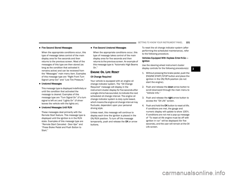
buttons. To reset the oil change indicator system (after
performing the scheduled maintenance), refer
to the following procedure.
Vehicles Equipped With Keyless Enter-N-Go —
Ignition
Use the steering wheel instrument cluster
display controls for the following procedure(s):
1. Without pressing the brake pedal, push the
ENGINE START/STOP button and place the
ignition in the ON/RUN position (do not
start the engine).
2. Push and release the down arrow button to
scroll downward through the main menu to
“Vehicle Info.”
3. Push and release the right arrow button to
access the ”Oil Life” screen.
4. Push and hold the OK button to reset oil life.
If conditions are met, the gauge and
numeric display will update to show 100%.
If conditions are not met a pop-up message
of “To reset oil life engine must be off with
ignition in run” will be displayed (for five
seconds), and the user will remain at the Oil
Life screen.
3
20_WD_OM_EN_USC_t.book Page 101
Page 104 of 464
102GETTING TO KNOW YOUR INSTRUMENT PANEL
5. Push and release the up or down arrow
button to exit the submenu screen.
NOTE:
If the indicator message illuminates when you
start the vehicle, the oil change indicator
system did not reset. If necessary, repeat this
procedure.
Secondary Method Of Resetting Engine Oil Life
1. Without pressing the brake pedal, push the ENGINE START/STOP button and place the
ignition to the ON/RUN position (do not
start the engine).
2. Fully press the accelerator pedal, slowly, three times within 10 seconds.
3. Without pushing the brake pedal, push the ENGINE START/STOP button once to return
the ignition to the OFF/LOCK position.
NOTE:
If the indicator message illuminates when you
start the vehicle, the oil change indicator
system did not reset. If necessary, repeat this
procedure.DISPLAY AND MESSAGES
Includes the following, but not limited to:
Front Seat Belts Unbuckled
Driver Seat Belt Unbuckled
Passenger Seat Belt Unbuckled
Traction Control Off
Washer Fluid Low
Oil Pressure Low
Oil Change Due
Fuel Low
Service Anti-lock Brake System
Service Electronic Throttle Control
Service Power Steering
Cruise Off
Cruise Ready
ACC Override
Cruise Set To XXX mph or km/h
Tire Pressure Screen With Low Tire(s)
Service Tire Pressure System
Park Brake Engaged
Brake Fluid Low
Engine Temperature Hot
Lights On
Right Front Turn Signal Light Out
Right Rear Turn Signal Light Out
Left Front Turn Signal Light Out
Left Rear Turn Signal Light Out
Ignition or Accessory On
Vehicle Not In Park
Remote Start Active Push Start Button
Remote Start Canceled Fuel Low
Remote Start Canceled Door Open
Remote Start Canceled Hood Open
Remote Start Canceled Liftgate Open
Remote Start Canceled Time Expired
Remote Start Disabled Start To Reset
20_WD_OM_EN_USC_t.book Page 102
Page 106 of 464
104GETTING TO KNOW YOUR INSTRUMENT PANEL
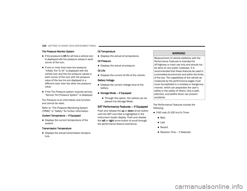
Tire Pressure Monitor System
If tire pressure is OK for all tires a vehicle icon
is displayed with tire pressure values in each
corner of the icon.
If one or more tires have low pressure,
“Inflate Tire To XX” is displayed with the
vehicle icon and the tire pressure values in
each corner of the icon with the pressure
value of the low tire are displayed in a
different color than the other tire pressure
value.
If the Tire Pressure system requires service,
“Service Tire Pressure System” is displayed.
Tire Pressure is an information only function,
and cannot be reset.
Refer to “Tire Pressure Monitoring System
(TPMS)” in “Safety” for further information.
Coolant Temperature — If Equipped
Displays the current temperature of the
coolant.
Transmission Temperature
Displays the actual transmission tempera -
ture. Oil Temperature
Displays the actual oil temperature.
Oil Pressure
Displays the actual oil pressure.
Oil Life
Displays the current oil life of the vehicle.
Battery Voltage
Displays the current voltage level of the
battery.
Storage Mode — If Equipped
Through this option, the vehicle can be
placed into Storage Mode.
SRT Performance Features — If Equipped
Push and release the up or down arrow button
until the SRT icon/title is highlighted in the
instrument cluster display. Push and release
the left or right arrow button to scroll through
the performance feature submenus. The Performance Features include the
following:0-60 mph (0-100 km/h) Timer
Best
Last
Recent
Reaction Time — If Selected
WARNING!
Measurement of vehicle statistics with the
Performance Features is intended for
off-highway or track use only and should not
be done on any public roadways. It is
recommended that these features be used in
a controlled environment and within the limits
of the law. The capabilities of the vehicle as
measured by the performance pages must
never be exploited in a reckless or dangerous
manner, which can jeopardize the user’s
safety or the safety of others. Only a safe,
attentive, and skillful driver can prevent
accidents.
20_WD_OM_EN_USC_t.book Page 104
Page 114 of 464
112GETTING TO KNOW YOUR INSTRUMENT PANEL
If the light continues to flash when the vehicle is
running, immediate service is required and you
may experience reduced performance, an
elevated/rough idle, or engine stall and your
vehicle may require towing. The light will come
on when the ignition is placed in the ON/RUN or
ACC/ON/RUN position and remain on briefly as
a bulb check. If the light does not come on
during starting, have the system checked by an
authorized dealer.
Engine Coolant Temperature Warning
Light
This warning light warns of an
overheated engine condition. If the
engine coolant temperature is too
high, this indicator will illuminate and
a single chime will sound. If the temperature
reaches the upper limit, a continuous chime will
sound for four minutes or until the engine is
able to cool, whichever comes first.
If the light turns on while driving, safely pull over
and stop the vehicle. If the Air Conditioning
(A/C) system is on, turn it off. Also, shift the
transmission into NEUTRAL (N) and idle the
vehicle. If the temperature reading does not
return to normal, turn the engine off
immediately and call for service. Refer to “If Your Engine Overheats” in “In Case
Of Emergency” for further information.
Hood Open Warning Light
This warning light will illuminate when
the hood is left open and not fully
closed.
NOTE:
If the vehicle is moving, there will also be a
single chime.
Liftgate Open Warning Light
This warning light will illuminate when
the liftgate is open.
NOTE:
If the vehicle is moving, there will also be a
single chime.
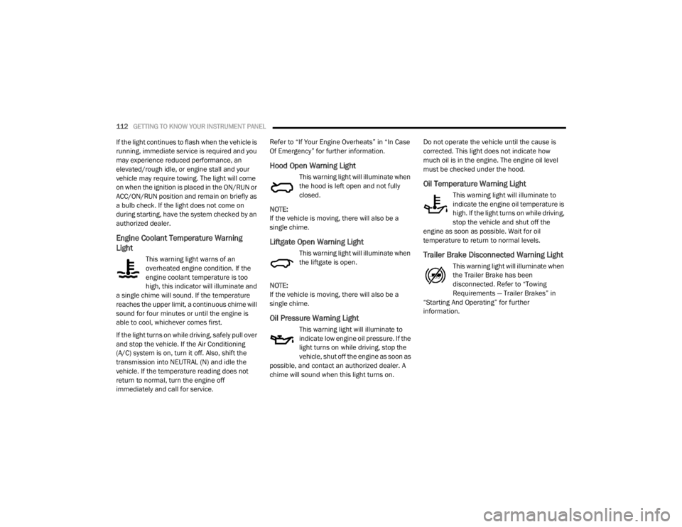
Oil Pressure Warning Light
This warning light will illuminate to
indicate low engine oil pressure. If the
light turns on while driving, stop the
vehicle, shut off the engine as soon as
possible, and contact an authorized dealer. A
chime will sound when this light turns on. Do not operate the vehicle until the cause is
corrected. This light does not indicate how
much oil is in the engine. The engine oil level
must be checked under the hood.
Oil Temperature Warning Light
This warning light will illuminate to
indicate the engine oil temperature is
high. If the light turns on while driving,
stop the vehicle and shut off the
engine as soon as possible. Wait for oil
temperature to return to normal levels.
Trailer Brake Disconnected Warning Light
This warning light will illuminate when
the Trailer Brake has been
disconnected. Refer to “Towing
Requirements — Trailer Brakes” in
“Starting And Operating” for further
information.
20_WD_OM_EN_USC_t.book Page 112
Page 296 of 464
294
SERVICING AND MAINTENANCE
SCHEDULED SERVICING — NON-SRT
Your vehicle is equipped with an automatic oil
change indicator system. The oil change
indicator system will remind you that it is time to
take your vehicle in for scheduled maintenance.
Based on engine operation conditions, the oil
change indicator message will illuminate. This
means that service is required for your vehicle.
Operating conditions such as frequent
short-trips, trailer tow, extremely hot or cold
ambient temperatures, and E85 fuel usage will
influence when the “Oil Change Required”
message is displayed. Severe Operating
Conditions can cause the change oil message
to illuminate as early as 3,500 miles
(5,600 km) since last reset. Have your vehicle
serviced as soon as possible, within the next
500 miles (805 km).An authorized dealer will reset the oil change
indicator message after completing the
scheduled oil change.
NOTE:
Under no circumstances should oil change
intervals exceed 10,000 miles (16,000 km),
12 months or 350 hours of engine run time,
whichever comes first. The 350 hours of engine
run or idle time is generally only a concern for
fleet customers.
Severe Duty All Models
Change Engine Oil at 4,000 miles (6,500 km) or
350 hours of engine run time if the vehicle is
operated in a dusty and off road environment or
is operated predominately at idle or only very
low engine RPM. This type of vehicle use is
considered Severe Duty.
Once A Month Or Before A Long Trip:Check engine oil level
Check windshield washer fluid level
Check the tire inflation pressures and look
for unusual wear or damage
Check the fluid levels of the coolant reservoir,
brake master cylinder and fill as needed.
Check function of all interior and exterior
lights
MAINTENANCE PLAN — NON-SRT
Required Maintenance
Refer to the Maintenance Plans on the following
pages for required maintenance.
20_WD_OM_EN_USC_t.book Page 294
Page 309 of 464
SERVICING AND MAINTENANCE307
(Continued)
CHECKING OIL LEVEL
To ensure proper lubrication of your vehicle's
engine, the engine oil must be maintained at
the correct level. Check the oil level at regular
intervals, such as every fuel stop. The best time
to check the engine oil level is about five
minutes after a fully warmed up engine is shut
off.
Checking the oil while the vehicle is on level
ground will improve the accuracy of the oil level
readings. Always maintain the oil level within
the SAFE zone on the dipstick. Adding one quart
of oil when the reading is at the bottom of the
SAFE zone will result in a reading at the top of
the safe zone on these engines.
ADDING WASHER FLUID
The instrument cluster display will indicate
when the washer fluid level is low. When the
sensor detects a low fluid level, the windshield
will light on the vehicle graphic outline and the
“WASHER FLUID LOW” message will be
displayed.
The fluid reservoir for the windshield washers
and the rear window washer is shared. The fluid
reservoir is located in the engine compartment,
be sure to check the fluid level at regular
intervals. Fill the reservoir with windshield
washer solvent only (not radiator antifreeze).
When refilling the washer fluid reservoir, take
some washer fluid and apply it to a cloth or
towel and wipe clean the wiper blades, this will
help blade performance. To prevent freeze-up
of your windshield washer system in cold
weather, select a solution or mixture that meets
or exceeds the temperature range of your
climate. This rating information can be found on
most washer fluid containers.
MAINTENANCE-FREE BATTERY
Your vehicle is equipped with a
maintenance-free battery. Water will never have
to be added, nor is periodic maintenance
required.
CAUTION!
Overfilling or underfilling will cause oil
aeration or loss of oil pressure. This could
damage your engine.
WARNING!
Commercially available windshield washer
solvents are flammable. They could ignite and
burn you. Care must be exercised when filling
or working around the washer solution.
WARNING!
Battery fluid is a corrosive acid solution and
can burn or even blind you. Do not allow
battery fluid to contact your eyes, skin, or
clothing. Do not lean over a battery when
attaching clamps. If acid splashes in eyes
or on skin, flush the area immediately with
large amounts of water. Refer to “Jump
Starting Procedure” in “In Case Of Emer -
gency” for further information.
7
20_WD_OM_EN_USC_t.book Page 307
Page 310 of 464
308SERVICING AND MAINTENANCE
PRESSURE WASHING
Cleaning the engine compartment with a high
pressure washer is not recommended.
DEALER SERVICE
An authorized dealer has the qualified service
personnel, special tools, and equipment to
perform all service operations in an expert
manner. Service Manuals are available which
include detailed service information for your
vehicle. Refer to these Service Manuals before
attempting any procedure yourself.
NOTE:
Intentional tampering with emissions control
systems may void your warranty and could
result in civil penalties being assessed against
you.
ENGINE OIL
Change Engine Oil — Non-SRT (If Equipped)
The oil change indicator system will remind you
that it is time to take your vehicle in for
scheduled maintenance. Refer to the
“Maintenance Plan” for further information.
NOTE:
Under no circumstances should oil change
intervals exceed 10,000 miles (16,000 km),
12 months or 350 hours of engine run time,
whichever comes first. The 350 hours of engine
run or idle time is generally only a concern for
fleet customers.
Battery gas is flammable and explosive.
Keep flame or sparks away from the
battery. Do not use a booster battery or any
other booster source with an output greater
than 12 Volts. Do not allow cable clamps to
touch each other.
Battery posts, terminals, and related acces -
sories contain lead and lead compounds.
Wash hands after handling.
CAUTION!
It is essential when replacing the cables on
the battery that the positive cable is
attached to the positive post and the nega -
tive cable is attached to the negative post.
Battery posts are marked positive (+) and
negative (-) and are identified on the battery
case. Cable clamps should be tight on the
terminal posts and free of corrosion.
If a “fast charger” is used while the battery
is in the vehicle, disconnect both vehicle
battery cables before connecting the
charger to the battery. Do not use a “fast
charger” to provide starting voltage.
WARNING! (Continued)
CAUTION!
Precautions have been taken to safeguard all
parts and connections however, the
pressures generated by these machines is
such that complete protection against water
ingress cannot be guaranteed.
WARNING!
You can be badly injured working on or
around a motor vehicle. Only do service work
for which you have the knowledge and the
proper equipment. If you have any doubt
about your ability to perform a service job,
take your vehicle to a competent mechanic.
20_WD_OM_EN_USC_t.book Page 308
Page 315 of 464
SERVICING AND MAINTENANCE313
(Continued)
2. Install the engine air cleaner filter cover onto the housing assembly locating tabs.
3. Latch the spring clips and lock the engine air cleaner filter cover to the housing
assembly.
AIR CONDITIONER MAINTENANCE
For best possible performance, your air
conditioner should be checked and serviced by
an authorized dealer at the start of each warm
season. This service should include cleaning of
the condenser fins and a performance test.
Drive belt tension should also be checked at
this time.
Refrigerant Recovery And Recycling
R-134a — If Equipped
R-134a Air Conditioning Refrigerant is a
hydrofluorocarbon (HFC) that is an
ozone-friendly substance. The manufacturer
recommends that air conditioning service be
performed by an authorized dealer or other
service facilities using recovery and recycling
equipment. NOTE:
Use only manufacturer approved A/C system
Polyalkylene Glycol (PAG) compressor oil and
refrigerants.
Refrigerant Recovery And Recycling —
R–1234yf
R–1234yf Air Conditioning Refrigerant is a
hydrofluoroolefin (HFO) that is endorsed by the
Environmental Protection Agency and is an
ozone-friendly substance with a low
global-warming potential. The manufacturer
recommends that air conditioning service be
performed by an authorized dealer using
recovery and recycling equipment.
NOTE:
Use only manufacturer approved A/C system
Polyalkylene Glycol (PAG) compressor oil, and
refrigerants.
WARNING!
Use only refrigerants and compressor lubri
-
cants approved by the manufacturer for
your air conditioning system. Some unap -
proved refrigerants are flammable and can
explode, injuring you. Other unapproved
refrigerants or lubricants can cause the
system to fail, requiring costly repairs.
Refer to Warranty Information Book, for
further warranty information.
The air conditioning system contains refrig -
erant under high pressure. To avoid risk of
personal injury or damage to the system,
adding refrigerant or any repair requiring
lines to be disconnected should be done by
an experienced technician.
CAUTION!
Do not use chemical flushes in your air
conditioning system as the chemicals can
damage your air conditioning components.
Such damage is not covered by the New
Vehicle Limited Warranty.
WARNING! (Continued)
7
20_WD_OM_EN_USC_t.book Page 313