transmission DODGE DURANGO 2020 Owners Manual
[x] Cancel search | Manufacturer: DODGE, Model Year: 2020, Model line: DURANGO, Model: DODGE DURANGO 2020Pages: 464, PDF Size: 22.14 MB
Page 6 of 464

4
ONBOARD DIAGNOSTIC SYSTEM — OBD II .... 120 Onboard Diagnostic System
(OBD II) Cybersecurity ................................120
EMISSIONS INSPECTION AND
MAINTENANCE PROGRAMS ............................ 121
SAFETY
SAFETY FEATURES ............................................ 122
Anti-Lock Brake System (ABS) ................. 122
Electronic Brake Control (EBC) System ....123
AUXILIARY DRIVING SYSTEMS ........................ 131
Blind Spot Monitoring (BSM) —
If Equipped .................................................131 Forward Collision Warning (FCW) With
Mitigation ...................................................136 Tire Pressure Monitoring System
(TPMS) ........................................................ 138
OCCUPANT RESTRAINT SYSTEMS .................. 143
Occupant Restraint Systems Features.....143
Important Safety Precautions ...................143Seat Belt Systems ..................................... 144Supplemental Restraint Systems (SRS) ...153Child Restraints .........................................163
Transporting Pets ......................................180 SAFETY TIPS ....................................................... 180
Transporting Passengers .......................... 180Exhaust Gas .............................................. 180
Safety Checks You Should Make
Inside The Vehicle ..................................... 181 Periodic Safety Checks You Should Make
Outside The Vehicle ................................... 183STARTING AND OPERATING
STARTING THE ENGINE .....................................184
Automatic Transmission............................ 184
Keyless Enter-N-Go — Ignition ................... 184
Normal Starting ......................................... 185
If Engine Fails To Start ............................. 187Cold Weather Operation (Below –22°F
Or −30°C) ................................................. 188 After Starting .............................................. 188
ENGINE BLOCK HEATER — IF EQUIPPED ........188
ENGINE BREAK-IN RECOMMENDATIONS –
NON-SRT .............................................................. 188
ENGINE BREAK-IN RECOMMENDATIONS –
SRT ....................................................................... 189
PARKING BRAKE ............................................... 190 AUTOMATIC TRANSMISSION ........................... 191
Ignition Park Interlock ............................... 192Brake/Transmission Shift Interlock
System ....................................................... 192 Fuel Economy (ECO) Mode........................ 192
Eight-Speed Automatic Transmission ...... 193
SPORT MODE — IF EQUIPPED.......................... 199
ALL-WHEEL DRIVE OPERATION ....................... 199
Single-Speed Operating Instructions/
Precautions— If Equipped ........................ 199 Electronically Shifted Transfer Case
(Three-Position Switch) — If Equipped...... 199 Shifting Procedure ..................................... 201
FUEL SAVER TECHNOLOGY 5.7L/6.4L
ONLY — IF EQUIPPED ........................................ 202
POWER STEERING............................................. 202
STOP/START SYSTEM — IF EQUIPPED ........... 203 Automatic Mode ........................................ 203
Possible Reasons The Engine Does Not
Autostop ..................................................... 204 To Start The Engine While In Autostop
Mode .......................................................... 204 To Manually Turn Off The Stop/Start
System........................................................ 205 To Manually Turn On The Stop/Start
System........................................................ 205 System Malfunction................................... 205
20_WD_OM_EN_USC_t.book Page 4
Page 8 of 464
6
RECREATIONAL TOWING (BEHIND
MOTORHOME, ETC.) ......................................... 253 Towing This Vehicle Behind Another
Vehicle .......................................................253 Recreational Towing — Rear-Wheel
Drive Models ..............................................254 Recreational Towing — All Wheel Drive
Models (Single-Speed Transfer Case) ......254 Recreational Towing — All-Wheel Drive
Models (Two-Speed Transfer Case) ..........254
DRIVING TIPS ..................................................... 257
On-Road Driving Tips .................................257
Off-Road Driving Tips .................................258
IN CASE OF EMERGENCY
HAZARD WARNING FLASHERS ....................... 261
ASSIST AND SOS MIRROR — IF EQUIPPED.... 261General Information ..................................265
BULB REPLACEMENT ....................................... 266
Replacement Bulbs .................................266
Bulb Replacement ....................................268
FUSES .................................................................. 269
General Information ..................................270Underhood Fuses.......................................270 JACKING AND TIRE CHANGING .......................275
Run Flat Tires ............................................. 276
Jack Location ............................................. 276
Spare Tire Stowage ................................... 277
Spare Tire Removal ................................... 277
Preparations For Jacking .......................... 279Jacking Instructions .................................. 279Road Tire Installation ................................ 283
JUMP STARTING ................................................ 283
Preparations For Jump Start ..................... 284Jump Starting Procedure .......................... 285
REFUELING IN EMERGENCY –
IF EQUIPPED ...................................................... 286
IF YOUR ENGINE OVERHEATS .........................287
MANUAL PARK RELEASE .................................. 287
FREEING A STUCK VEHICLE .............................289
TOWING A DISABLED VEHICLE .......................290 Rear Wheel Drive Models.......................... 292All Wheel Drive Models.............................. 292
TOWING A DISABLED SRT VEHICLE ................293
ENHANCED ACCIDENT RESPONSE SYSTEM
(EARS) .................................................................293
EVENT DATA RECORDER (EDR) .......................293
SERVICING AND MAINTENANCE
SCHEDULED SERVICING — NON-SRT .............. 294
Maintenance Plan — Non-SRT .................. 294Heavy Duty Use Of The Vehicle................. 298
SCHEDULED SERVICING – SRT ....................... 298
Maintenance Plan — SRT .......................... 300
ENGINE COMPARTMENT .................................. 304
3.6L Engine ................................................ 304
5.7L Engine ................................................ 305
6.4L Engine ................................................ 306
Checking Oil Level ..................................... 307
Adding Washer Fluid ................................ 307
Maintenance-Free Battery ....................... 307Pressure Washing...................................... 308
DEALER SERVICE .............................................. 308
Engine Oil .................................................. 308
Engine Oil Filter ......................................... 311Engine Air Cleaner Filter............................ 311Air Conditioner Maintenance .................... 313Accessory Drive Belt Inspection ............... 315Body Lubrication ....................................... 316
Windshield Wiper Blades ......................... 316
Exhaust System ........................................ 320
Cooling System .......................................... 321
Brake System ............................................ 325Automatic Transmission............................ 326Front/Rear Axle Fluid ............................... 327Transfer Case ............................................ 327
20_WD_OM_EN_USC_t.book Page 6
Page 11 of 464
9
INTRODUCTION
Dear Customer, congratulations on selecting your new vehicle. Be assured that it represents precision workmanship, distinctive styling, and high quality.
This is a specialized utility vehicle. It can go places and perform tasks that are not intended for conventional passenger vehicles. It handles and
maneuvers differently from many passenger vehicles both on-road and off-road, so take time to become familiar with your vehicle. If equipped, the
two-wheel drive version of this vehicle was designed for on-road use only. It is not intended for off-road driving or use in other severe conditions suited
for a four-wheel drive vehicle. Before you start to drive this vehicle, read the Owner’s Manual. Be sure you are familiar with all vehicle controls,
particularly those used for braking, steering, transmission, and transfer case shifting. Learn how your vehicle handles on different road surfaces. Your
driving skills will improve with experience. When driving off-road, or working the vehicle, don’t overload the vehicle or expect the vehicle to overcome
the natural laws of physics. Always observe federal, state, provincial and local laws wherever you drive. As with other vehicles of this type, failure to
operate this vehicle correctly may result in loss of control or a collision. Refer to “Driving Tips” in “Starting and Operating” for further information.
This Owner's Manual has been prepared with the assistance of service and engineering specialists to acquaint you with the operation and maintenance
of your vehicle. It is supplemented by customer-oriented documents. Within this information, you will find a description of the services that FCA US LLC
offers to its customers as well as the details of the terms and conditions for maintaining its validity. Please take the time to read all of these publications
carefully before driving your vehicle for the first time. Following the instructions, recommendations, tips, and important warnings in this manual will help
assure safe and enjoyable operation of your vehicle.
This Owner's Manual describes all versions of this vehicle. Options and equipment dedicated to specific markets or versions are not expressly indicated
in the text. Therefore, you should only consider the information which is related to the trim level, engine, and version that you have purchased. Any
content introduced throughout the Owner's Information, that may or may not be applicable to your vehicle, will be identified with the wording “If
Equipped”. All data contained in this publication are intended to help you use your vehicle in the best possible way. FCA US LLC aims at a constant
improvement of the vehicles produced. For this reason, it reserves the right to make changes to the model described for technical and/or commercial
reasons. For further information, contact an authorized dealer.
When it comes to service, remember that authorized dealers know your vehicle best, have factory-trained technicians and genuine MOPAR® parts, and
care about your satisfaction.1
20_WD_OM_EN_USC_t.book Page 9
Page 20 of 464
18GETTING TO KNOW YOUR VEHICLE
(Continued)
NOTE:
In case the ignition switch does not change with
the push of a button, the key fob may have a low
or depleted battery. In this situation, a back up
method can be used to operate the ignition
switch. Put the nose side of the key fob (side
opposite of the emergency key) against the
START/STOP ignition button and push to
operate the ignition switch.
IGNITION OR ACCESSORY ON MESSAGE
Upon opening the driver's door when the
ignition is in ACC or ON (engine not running), a
chime will sound to remind you to place the
ignition in the OFF position. In addition to the
chime, the ignition or accessory on message will
display in the cluster.
NOTE:
With the Uconnect system, the power window
switches, radio, power sunroof (if equipped),
and power outlets will remain active for up to
10 minutes after the ignition is placed in the
OFF position. Opening either front door will
cancel this feature. The timing for this feature is programmable.
Refer to “Uconnect Settings” in “Multimedia”
for further information.
DEPLETED KEY FOB BATTERY
Key Not Detected Feature
If the ignition position does not change with a
push of the ignition button, and the instrument
cluster display message “Key Fob Not
Detected” is being displayed, the key fob may
have a low or depleted battery. In this situation,
a back up method can be used to operate the
keyless push button ignition.
WARNING!
Before exiting a vehicle, always shift the
automatic transmission into PARK and
apply the parking brake. Always make sure
the keyless ignition node is in the “OFF”
mode, remove the key fob from the vehicle
and lock the vehicle.
Never leave children alone in a vehicle, or
with access to an unlocked vehicle.
Allowing children to be in a vehicle unat
-
tended is dangerous for a number of
reasons. A child or others could be seriously
or fatally injured. Children should be
warned not to touch the parking brake,
brake pedal or the gear selector.
Do not leave the key fob in or near the
vehicle, or in a location accessible to chil-
dren, and do not leave the ignition of a
vehicle equipped with Keyless Enter-N-Go
in the ACC or ON/RUN mode. A child could
operate power windows, other controls, or
move the vehicle.
Do not leave children or animals inside
parked vehicles in hot weather. Interior
heat build-up may cause serious injury or
death.
CAUTION!
An unlocked vehicle is an invitation. Always
remove the key fobs from vehicle, place the
ignition in the OFF position and lock all doors
when leaving the vehicle unattended.
WARNING! (Continued)
20_WD_OM_EN_USC_t.book Page 18
Page 21 of 464
GETTING TO KNOW YOUR VEHICLE19
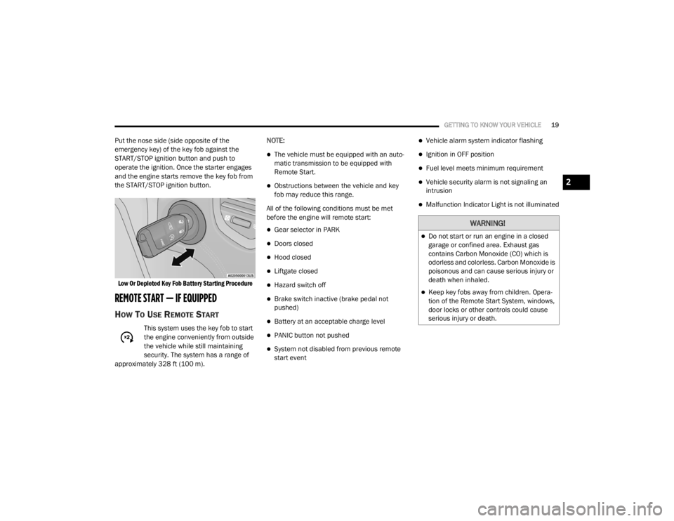
Put the nose side (side opposite of the
emergency key) of the key fob against the
START/STOP ignition button and push to
operate the ignition. Once the starter engages
and the engine starts remove the key fob from
the START/STOP ignition button.
Low Or Depleted Key Fob Battery Starting Procedure
REMOTE START — IF EQUIPPED
HOW TO USE REMOTE START
This system uses the key fob to start
the engine conveniently from outside
the vehicle while still maintaining
security. The system has a range of
approximately 328 ft (100 m). NOTE:
The vehicle must be equipped with an auto
-
matic transmission to be equipped with
Remote Start.
Obstructions between the vehicle and key
fob may reduce this range.
All of the following conditions must be met
before the engine will remote start:
Gear selector in PARK
Doors closed
Hood closed
Liftgate closed
Hazard switch off
Brake switch inactive (brake pedal not
pushed)
Battery at an acceptable charge level
PANIC button not pushed
System not disabled from previous remote
start event
Vehicle alarm system indicator flashing
Ignition in OFF position
Fuel level meets minimum requirement
Vehicle security alarm is not signaling an
intrusion
Malfunction Indicator Light is not illuminated
WARNING!
Do not start or run an engine in a closed
garage or confined area. Exhaust gas
contains Carbon Monoxide (CO) which is
odorless and colorless. Carbon Monoxide is
poisonous and can cause serious injury or
death when inhaled.
Keep key fobs away from children. Opera -
tion of the Remote Start System, windows,
door locks or other controls could cause
serious injury or death.
2
20_WD_OM_EN_USC_t.book Page 19
Page 53 of 464

GETTING TO KNOW YOUR VEHICLE51
NOTE:
Your vehicle is equipped with plastic head -
light and fog light (if equipped) lenses that
are lighter and less susceptible to stone
breakage than glass lights. Plastic is not as
scratch resistant as glass and therefore
different lens cleaning procedures must be
followed.
To minimize the possibility of scratching the
lenses and reducing light output, avoid
wiping with a dry cloth. To remove road dirt,
wash with a mild soap solution followed by
rinsing.
DAYTIME RUNNING LIGHTS (DRLS) —
I
F EQUIPPED
The Daytime Running Lights (DRLs) come on
whenever the engine is running, and the
transmission is not in the PARK position. The lights will remain on until the ignition is
placed in the OFF or ACC position, or the parking
brake is engaged. The headlight switch must be
used for normal night time driving.
NOTE:
If allowed by law in the country in which the
vehicle was purchased, the Daytime Running
Lights can be turned on and off using the
Uconnect system, refer to “Uconnect
Settings” in “Multimedia” for further informa
-
tion.
On some vehicles, the Daytime Running
Lights may deactivate, or reduce intensity, on
one side of the vehicle (when a turn signal is
activated on that side), or on both sides of
the vehicle (when the hazard warning lights
are activated).
HIGH/LOW BEAM SWITCH
Push the multifunction lever toward the
instrument panel to switch the headlights to
high beams. Pulling the multifunction back
toward the steering wheel will turn the low
beams back on, or shut the high beams off.
AUTOMATIC HIGH BEAM — IF EQUIPPED
The Automatic High Beam Headlamp Control
system provides increased forward lighting at
night by automating high beam control through
the use of a digital camera mounted on the
inside rearview mirror. This camera detects
vehicle specific light and automatically switches
from high beams to low beams until the
approaching vehicle is out of view.
NOTE:
The Automatic High Beam Headlamp Control
can be turned on or off by selecting or dese -
lecting “Auto High Beam” within your Ucon -
nect settings, as well as turning the headlight
switch to the AUTO position. Refer to “Ucon -
nect Settings” in “Multimedia” for further
information.
Broken, muddy, or obstructed headlights and
taillights of vehicles in the field of view will
cause headlights to remain on longer (closer
to the vehicle). Also, dirt, film, and other
obstructions on the windshield or camera
lens will cause the system to function
improperly.
CAUTION!
Do not use abrasive cleaning components,
solvents, steel wool or other abrasive
materials to clean the lenses.
2
20_WD_OM_EN_USC_t.book Page 51
Page 59 of 464

GETTING TO KNOW YOUR VEHICLE57
RAIN SENSING WIPERS — IF EQUIPPED
This feature senses rain or snowfall on the
windshield and automatically activates the
wipers for the driver. The feature is especially
useful for road splash or overspray from the
windshield washers of the vehicle ahead.
Rotate the end of the multifunction lever to one
of four settings to activate this feature.
The sensitivity of the system can be adjusted
with the multifunction lever. Wiper delay
position one is the least sensitive, and wiper
delay position four is the most sensitive.
NOTE:
Wiper delay position three should be used for
normal rain conditions.
Settings one and two can be used if the driver
desires less wiper sensitivity. Setting four can
be used if the driver desires more sensitivity.
Place the wiper switch in the OFF position when
not using the system. NOTE:The Rain Sensing feature will not operate
when the wiper switch is in the low or
high-speed position.
The Rain Sensing feature may not function
properly when ice, or dried salt water is
present on the windshield.
Use of Rain-X or products containing wax or
silicone may reduce Rain Sensing perfor
-
mance.
The Rain Sensing feature can be turned on
and off using the Uconnect System, refer to
“Uconnect Settings” in “Multimedia” for
further information. The Rain Sensing system has protection
features for the wiper blades and arms, and will
not operate under the following conditions:
Low Ambient Temperature
— When the igni-
tion is first placed in the ON position, the Rain
Sensing system will not operate until the
wiper switch is moved, vehicle speed is
greater than 3 mph (5 km/h), or the outside
temperature is greater than 32°F (0°C).
Transmission In NEUTRAL Position — When
the ignition is in the ON position, and the gear
selector is in NEUTRAL, the Rain Sensing
system will not operate until the wiper switch
is moved, vehicle speed is greater than
3 mph (5 km/h), or the gear selector is
moved out of NEUTRAL.
2
20_WD_OM_EN_USC_t.book Page 57
Page 81 of 464
GETTING TO KNOW YOUR VEHICLE79
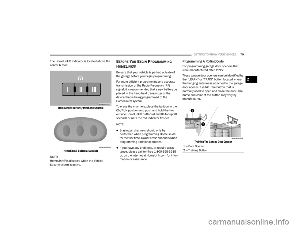
The HomeLink® indicator is located above the
center button.
HomeLink® Buttons/Overhead ConsoleHomeLink® Buttons/Sunvisor
NOTE:
HomeLink® is disabled when the Vehicle
Security Alarm is active.BEFORE YOU BEGIN PROGRAMMING
H
OMELINK®
Be sure that your vehicle is parked outside of
the garage before you begin programming.
For more efficient programming and accurate
transmission of the Radio Frequency (RF)
signal, it is recommended that a new battery be
placed in the hand-held transmitter of the
device that is being programmed to the
HomeLink® system.
To erase the channels, place the ignition in the
ON/RUN position and push and hold the two
outside HomeLink® buttons (I and III) for up 20
seconds or until the red indicator flashes.
NOTE:
Erasing all channels should only be
performed when programming HomeLink®
for the first time. Do not erase channels when
programming additional buttons.
If you have any problems, or require assis -
tance, please call toll-free 1-800-355-3515
or, on the Internet at HomeLink.com for infor -
mation or assistance.
Programming A Rolling Code
For programming garage door openers that
were manufactured after 1995:
These garage door openers can be identified by
the “LEARN” or “TRAIN” button located where
the hanging antenna is attached to the garage
door opener. It is NOT the button that is
normally used to open and close the door. The
name and color of the button may vary by
manufacturer.
Training The Garage Door Opener
1 — Door Opener
2 — Training Button
2
20_WD_OM_EN_USC_t.book Page 79
Page 83 of 464

GETTING TO KNOW YOUR VEHICLE81
Release both buttons after the indicator
light changes from slow to rapid.
5. Push and hold the programmed HomeLink® button and observe the
indicator light.
If the indicator light stays on constantly,
programming is complete and the garage
door/device should activate when the
HomeLink® button is pushed.
To program the two remaining Home -
Link® buttons, repeat each step for each
remaining button. DO NOT erase the
channels.
CANADIAN/GATE OPERATOR
P
ROGRAMMING
For programming transmitters in Canada/
United States that require the transmitter
signals to “time-out” after several seconds of
transmission:
Canadian Radio Frequency (RF) laws require
transmitter signals to time-out (or quit) after
several seconds of transmission, which may not
be long enough for HomeLink® to pick up the
signal during programming. Similar to this Canadian law, some U.S. gate
operators are designed to time-out in the same
manner.
It may be helpful to unplug the device during the
cycling process to prevent possible overheating
of the garage door or gate motor.
1. Place the ignition in the ON/RUN position.
NOTE:
For vehicles equipped with Keyless Enter-N-Go,
place the ignition in the RUN position with the
engine on. Make sure while programming
HomeLink® with the engine on that your vehicle
is outside of your garage, or that the garage
door remains open at all times.
2. Place the hand-held transmitter 1 to
3 inches (3 to 8 cm) away from the
HomeLink® button you wish to program
while keeping the HomeLink® indicator
light in view.
3. Continue to push and hold the HomeLink® button while you push and release (“cycle”)
your hand-held transmitter every two
seconds until HomeLink® has successfully
accepted the frequency signal. The indicator light will flash slowly and then
rapidly when fully trained.
4. Watch for the HomeLink® indicator to change flash rates. When it changes, it is
programmed. It may take up to 30 seconds
or longer in rare cases. The garage door
may open and close while you are
programming.
5. Push and hold the programmed HomeLink® button and observe the
indicator light.
NOTE:
If the indicator light stays on constantly,
programming is complete and the garage
door/device should activate when the Home -
Link® button is pushed.
To program the two remaining HomeLink®
buttons, repeat each step for each remaining
button. DO NOT erase the channels.
If you unplugged the garage door opener/
device for programming, plug it back in at this
time.
2
20_WD_OM_EN_USC_t.book Page 81
Page 105 of 464

GETTING TO KNOW YOUR INSTRUMENT PANEL103
Service Air Bag System
Service Air Bag Warning Light
Door Open
Doors Open
Liftgate Open
Hood Open
Shift Not Allowed
Vehicle Speed Too High To Shift to D
Vehicle Speed is Too High to Shift to R
Vehicle Speed is Too High to Shift to P
Service Transmission
Service Shifter
The Reconfigurable Telltales section is divided
into the white or yellow telltales area on the left,
and the green or red telltales area on the right.
INSTRUMENT CLUSTER DISPLAY MENU
I
TEMS
The instrument cluster display can be used to
view the main menu items for several features.
Use the up and down arrow buttons to scroll
through the driver interactive display menu
options until the desired menu is reached.
NOTE:
Depending on the vehicle’s options, feature
settings may vary.
Speedometer
Non - SRT
Push and release the up or down arrow button
until the main gauge menu icon is displayed in
the instrument cluster display. Push and
release the left or right arrow button to select
the analog or digital type speedometer display.
Push and release the OK button to toggle units
(mph or km/h) (If Equipped) of the
speedometer. SRT
Push and release the
up or down arrow button
until the main gauge menu icon is displayed in
the instrument cluster display. Push and
release the left or right arrow buttons to change
between large and small speedometer display.
Push and release the OK button to toggle units
(mph or km/h) (If Equipped) of the
speedometer.
Vehicle Info
Push and release the up or down arrow button
until the Vehicle Info icon/title is highlighted in
the instrument cluster display. Push the left or
right arrow button to scroll through the
information submenus.
3
20_WD_OM_EN_USC_t.book Page 103