warning light DODGE DURANGO 2020 Owners Manual
[x] Cancel search | Manufacturer: DODGE, Model Year: 2020, Model line: DURANGO, Model: DODGE DURANGO 2020Pages: 464, PDF Size: 22.14 MB
Page 5 of 464
3
EXTERIOR LIGHTS ................................................50 Multifunction Lever ...................................... 50
Headlight Switch ......................................... 50
Daytime Running Lights (DRLs) —
If Equipped .................................................. 51 High/Low Beam Switch ............................... 51
Automatic High Beam — If Equipped .......... 51
Flash-To-Pass .............................................. 52
Automatic Headlights ................................. 52
Parking Lights And Panel Lights ................. 52
Headlights On Automatically With
Wipers........................................................... 52 Headlight Delay ............................................ 52
Lights-On Reminder ..................................... 52
Fog Lights — If Equipped ............................. 53
Turn Signals ................................................. 53
Lane Change Assist — If Equipped ............. 53
Battery Saver................................................ 53
INTERIOR LIGHTS ................................................54
Courtesy Lights ............................................ 54
WINDSHIELD WIPERS AND WASHERS .............55
Windshield Wiper Operation ....................... 55
Rain Sensing Wipers — If Equipped ........... 57
Rear Window Wiper/Washer ...................... 58
CLIMATE CONTROLS ............................................58
Automatic Climate Control Overview .......... 58
Climate Control Functions ........................... 68
Automatic Temperature Control (ATC) ....... 69
Operating Tips ............................................. 69 WINDOWS ............................................................ 71
Power Windows............................................ 71
Wind Buffeting ............................................ 72
POWER SUNROOF — IF EQUIPPED .................... 73
Opening Sunroof .......................................... 73
Closing Sunroof............................................ 74
Wind Buffeting ............................................ 74
Sunshade Operation.................................... 74
Pinch Protect Feature.................................. 74
Sunroof Maintenance.................................. 74
Ignition Off Operation .................................. 74
HOOD ..................................................................... 75
Opening The Hood ....................................... 75
Closing The Hood ......................................... 75
LIFTGATE ............................................................... 75
Power Liftgate — If Equipped ...................... 75
Cargo Area Features ................................... 77
GARAGE DOOR OPENER — IF EQUIPPED ......... 78
Before You Begin Programming
HomeLink® .................................................. 79 Canadian/Gate Operator Programming ..... 81
Using HomeLink®........................................ 82
Security......................................................... 82
Troubleshooting Tips ................................... 82
General Information .................................... 83
INTERNAL EQUIPMENT ........................................ 83
Storage ......................................................... 83
Cupholders ................................................... 86
Electrical Power Outlets ............................. 87
Power Inverter — If Equipped ...................... 90
Sunglasses Bin Door ................................... 90 ROOF LUGGAGE RACK — IF EQUIPPED ............90
Deploying The Crossbars ............................ 91
Stowing The Crossbars................................ 93
GETTING TO KNOW YOUR
INSTRUMENT PANEL
INSTRUMENT CLUSTER .......................................95Instrument Cluster Descriptions................. 96
SRT INSTRUMENT CLUSTER ...............................97
SRT Instrument Cluster Descriptions ......... 98
INSTRUMENT CLUSTER DISPLAY .......................99
Location And Controls ................................. 99
Engine Oil Life Reset ................................ 101
Display And Messages .............................. 102
Instrument Cluster Display Menu
Items .......................................................... 103 Battery Saver On/Battery Saver Mode
Message — Electrical Load Reduction
Actions — If Equipped ............................... 108
WARNING LIGHTS AND MESSAGES ............... 109
Red Warning Lights ................................... 110
Yellow Warning Lights ............................... 113Yellow Indicator Lights .............................. 117
Green Indicator Lights ............................... 117White Indicator Lights ............................... 119Blue Indicator Lights ................................. 119
20_WD_OM_EN_USC_t.book Page 3
Page 12 of 464
10
HOW TO USE THIS MANUAL
ESSENTIAL INFORMATION
Consult the Table of Contents to determine which section contains the
information you desire.
Since the specification of your vehicle depends on the items of equipment
ordered, certain descriptions and illustrations may differ from your
vehicle's equipment.
The detailed Index at the back of this Owner's Manual contains a
complete listing of all subjects.
SYMBOLS
Some vehicle components have colored labels whose symbols indicate
precautions to be observed when using this component. Refer to
“Warning Lights and Messages” in “Getting To Know Your Instrument
Panel” for further information on the symbols used in your vehicle.
ROLLOVER WARNING
Utility vehicles have a significantly higher rollover rate than other types of
vehicles. This vehicle has a higher ground clearance and a higher center
of gravity than many passenger vehicles. It is capable of performing better
in a wide variety of off-road applications. Driven in an unsafe manner, all
vehicles can go out of control. Because of the higher center of gravity, if
this vehicle is out of control, it may roll over while some other vehicles may
not.Do not attempt sharp turns, abrupt maneuvers, or other unsafe driving
actions that can cause loss of vehicle control. Failure to operate this
vehicle safely may result in a collision, rollover of the vehicle, and severe
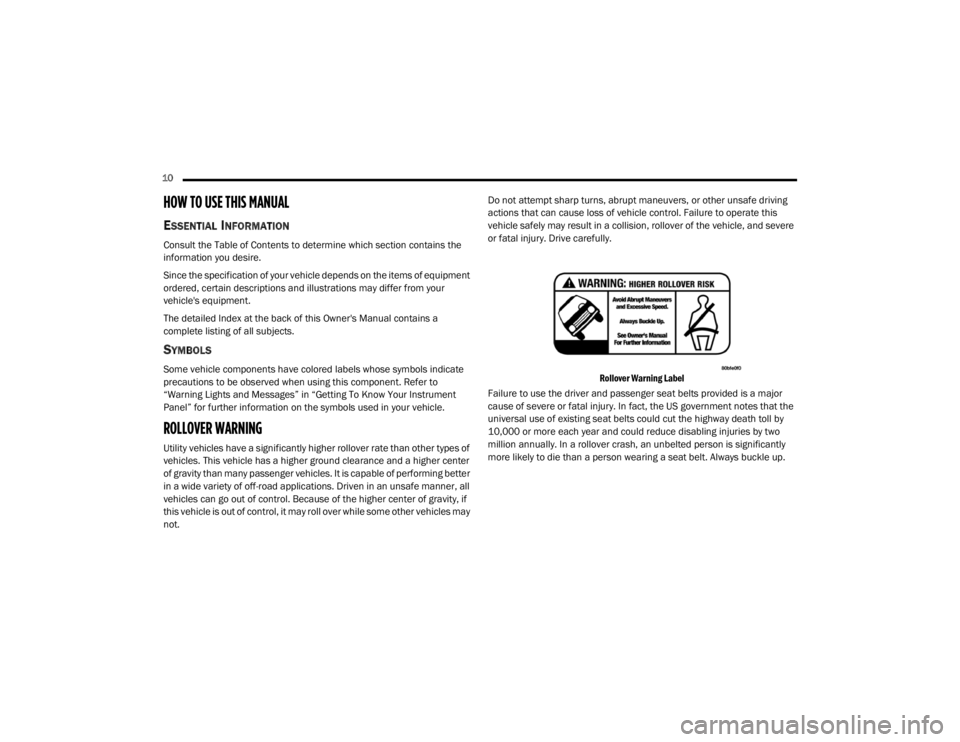
or fatal injury. Drive carefully.
Rollover Warning Label
Failure to use the driver and passenger seat belts provided is a major
cause of severe or fatal injury. In fact, the US government notes that the
universal use of existing seat belts could cut the highway death toll by
10,000 or more each year and could reduce disabling injuries by two
million annually. In a rollover crash, an unbelted person is significantly
more likely to die than a person wearing a seat belt. Always buckle up.
20_WD_OM_EN_USC_t.book Page 10
Page 18 of 464
16GETTING TO KNOW YOUR VEHICLE
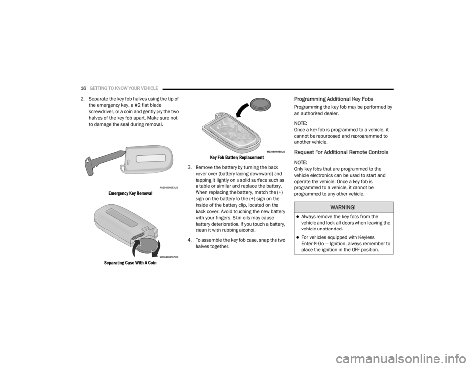
2. Separate the key fob halves using the tip of
the emergency key, a #2 flat blade
screwdriver, or a coin and gently pry the two
halves of the key fob apart. Make sure not
to damage the seal during removal.
Emergency Key Removal
Separating Case With A Coin Key Fob Battery Replacement
3. Remove the battery by turning the back cover over (battery facing downward) and
tapping it lightly on a solid surface such as
a table or similar and replace the battery.
When replacing the battery, match the (+)
sign on the battery to the (+) sign on the
inside of the battery clip, located on the
back cover. Avoid touching the new battery
with your fingers. Skin oils may cause
battery deterioration. If you touch a battery,
clean it with rubbing alcohol.
4. To assemble the key fob case, snap the two halves together.Programming Additional Key Fobs
Programming the key fob may be performed by
an authorized dealer.
NOTE:
Once a key fob is programmed to a vehicle, it
cannot be repurposed and reprogrammed to
another vehicle.
Request For Additional Remote Controls
NOTE:
Only key fobs that are programmed to the
vehicle electronics can be used to start and
operate the vehicle. Once a key fob is
programmed to a vehicle, it cannot be
programmed to any other vehicle.
WARNING!
Always remove the key fobs from the
vehicle and lock all doors when leaving the
vehicle unattended.
For vehicles equipped with Keyless
Enter-N-Go — Ignition, always remember to
place the ignition in the OFF position.
20_WD_OM_EN_USC_t.book Page 16
Page 21 of 464
GETTING TO KNOW YOUR VEHICLE19
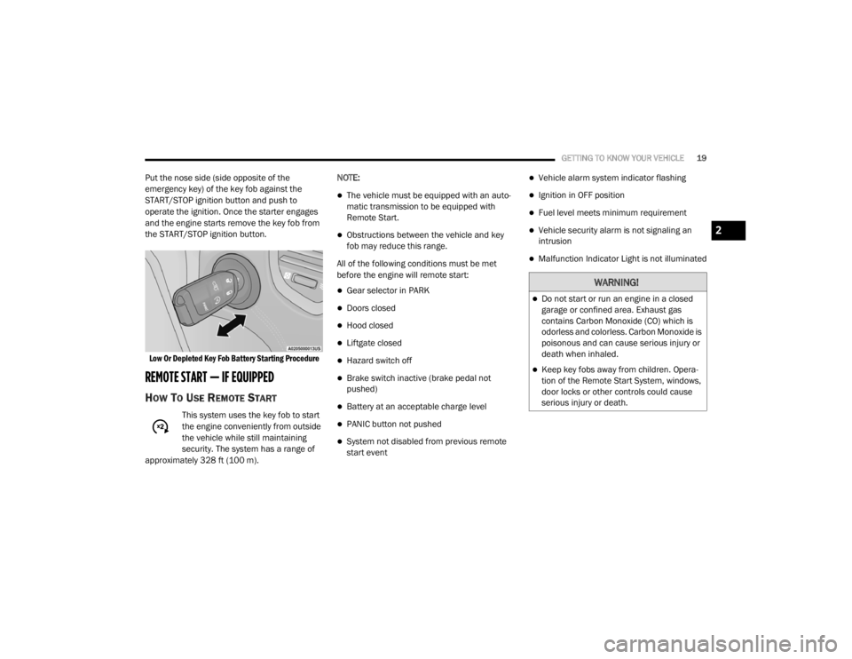
Put the nose side (side opposite of the
emergency key) of the key fob against the
START/STOP ignition button and push to
operate the ignition. Once the starter engages
and the engine starts remove the key fob from
the START/STOP ignition button.
Low Or Depleted Key Fob Battery Starting Procedure
REMOTE START — IF EQUIPPED
HOW TO USE REMOTE START
This system uses the key fob to start
the engine conveniently from outside
the vehicle while still maintaining
security. The system has a range of
approximately 328 ft (100 m). NOTE:
The vehicle must be equipped with an auto
-
matic transmission to be equipped with
Remote Start.
Obstructions between the vehicle and key
fob may reduce this range.
All of the following conditions must be met
before the engine will remote start:
Gear selector in PARK
Doors closed
Hood closed
Liftgate closed
Hazard switch off
Brake switch inactive (brake pedal not
pushed)
Battery at an acceptable charge level
PANIC button not pushed
System not disabled from previous remote
start event
Vehicle alarm system indicator flashing
Ignition in OFF position
Fuel level meets minimum requirement
Vehicle security alarm is not signaling an
intrusion
Malfunction Indicator Light is not illuminated
WARNING!
Do not start or run an engine in a closed
garage or confined area. Exhaust gas
contains Carbon Monoxide (CO) which is
odorless and colorless. Carbon Monoxide is
poisonous and can cause serious injury or
death when inhaled.
Keep key fobs away from children. Opera -
tion of the Remote Start System, windows,
door locks or other controls could cause
serious injury or death.
2
20_WD_OM_EN_USC_t.book Page 19
Page 43 of 464
GETTING TO KNOW YOUR VEHICLE41
(Continued)
Vehicles Equipped With Remote Start
On models that are equipped with remote start,
the heated seats can be programmed to come
on during a remote start.
This feature can be programmed through the
Uconnect system. Refer to “Uconnect Settings”
in “Multimedia” for further information.Rear Heated Seats — If Equipped
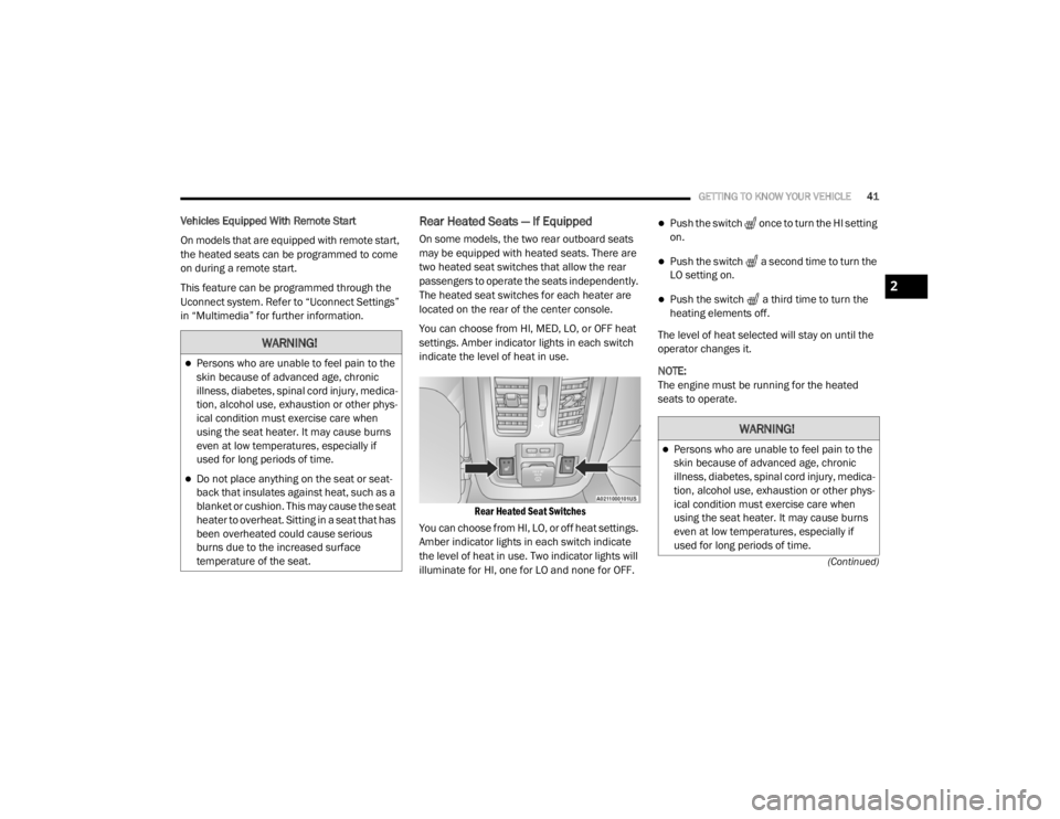
On some models, the two rear outboard seats
may be equipped with heated seats. There are
two heated seat switches that allow the rear
passengers to operate the seats independently.
The heated seat switches for each heater are
located on the rear of the center console.
You can choose from HI, MED, LO, or OFF heat
settings. Amber indicator lights in each switch
indicate the level of heat in use.
Rear Heated Seat Switches
You can choose from HI, LO, or off heat settings.
Amber indicator lights in each switch indicate
the level of heat in use. Two indicator lights will
illuminate for HI, one for LO and none for OFF.
Push the switch once to turn the HI setting
on.
Push the switch a second time to turn the
LO setting on.
Push the switch a third time to turn the
heating elements off.
The level of heat selected will stay on until the
operator changes it.
NOTE:
The engine must be running for the heated
seats to operate.
WARNING!
Persons who are unable to feel pain to the
skin because of advanced age, chronic
illness, diabetes, spinal cord injury, medica -
tion, alcohol use, exhaustion or other phys -
ical condition must exercise care when
using the seat heater. It may cause burns
even at low temperatures, especially if
used for long periods of time.
Do not place anything on the seat or seat -
back that insulates against heat, such as a
blanket or cushion. This may cause the seat
heater to overheat. Sitting in a seat that has
been overheated could cause serious
burns due to the increased surface
temperature of the seat.
WARNING!
Persons who are unable to feel pain to the
skin because of advanced age, chronic
illness, diabetes, spinal cord injury, medica -
tion, alcohol use, exhaustion or other phys -
ical condition must exercise care when
using the seat heater. It may cause burns
even at low temperatures, especially if
used for long periods of time.
2
20_WD_OM_EN_USC_t.book Page 41
Page 50 of 464
48GETTING TO KNOW YOUR VEHICLE
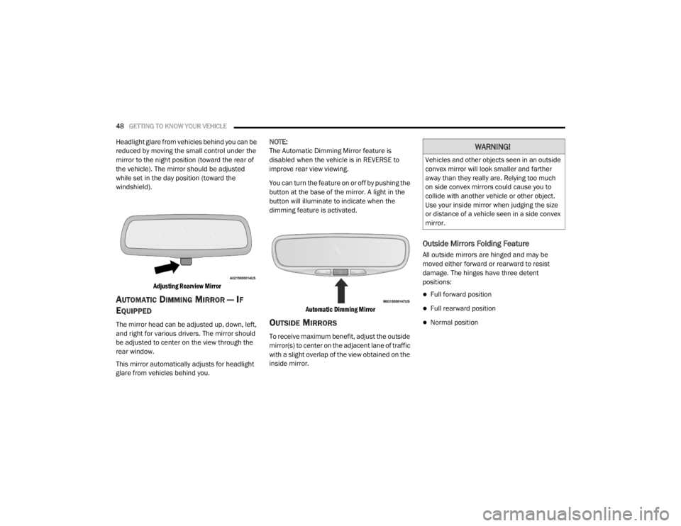
Headlight glare from vehicles behind you can be
reduced by moving the small control under the
mirror to the night position (toward the rear of
the vehicle). The mirror should be adjusted
while set in the day position (toward the
windshield).
Adjusting Rearview Mirror
AUTOMATIC DIMMING MIRROR — IF
E
QUIPPED
The mirror head can be adjusted up, down, left,
and right for various drivers. The mirror should
be adjusted to center on the view through the
rear window.
This mirror automatically adjusts for headlight
glare from vehicles behind you. NOTE:
The Automatic Dimming Mirror feature is
disabled when the vehicle is in REVERSE to
improve rear view viewing.
You can turn the feature on or off by pushing the
button at the base of the mirror. A light in the
button will illuminate to indicate when the
dimming feature is activated.
Automatic Dimming Mirror
OUTSIDE MIRRORS
To receive maximum benefit, adjust the outside
mirror(s) to center on the adjacent lane of traffic
with a slight overlap of the view obtained on the
inside mirror.
Outside Mirrors Folding Feature
All outside mirrors are hinged and may be
moved either forward or rearward to resist
damage. The hinges have three detent
positions:
Full forward position
Full rearward position
Normal position
WARNING!
Vehicles and other objects seen in an outside
convex mirror will look smaller and farther
away than they really are. Relying too much
on side convex mirrors could cause you to
collide with another vehicle or other object.
Use your inside mirror when judging the size
or distance of a vehicle seen in a side convex
mirror.
20_WD_OM_EN_USC_t.book Page 48
Page 53 of 464
GETTING TO KNOW YOUR VEHICLE51
NOTE:
Your vehicle is equipped with plastic head -
light and fog light (if equipped) lenses that
are lighter and less susceptible to stone
breakage than glass lights. Plastic is not as
scratch resistant as glass and therefore
different lens cleaning procedures must be
followed.
To minimize the possibility of scratching the
lenses and reducing light output, avoid
wiping with a dry cloth. To remove road dirt,
wash with a mild soap solution followed by
rinsing.
DAYTIME RUNNING LIGHTS (DRLS) —
I
F EQUIPPED
The Daytime Running Lights (DRLs) come on
whenever the engine is running, and the
transmission is not in the PARK position. The lights will remain on until the ignition is
placed in the OFF or ACC position, or the parking
brake is engaged. The headlight switch must be
used for normal night time driving.
NOTE:
If allowed by law in the country in which the
vehicle was purchased, the Daytime Running
Lights can be turned on and off using the
Uconnect system, refer to “Uconnect
Settings” in “Multimedia” for further informa
-
tion.
On some vehicles, the Daytime Running
Lights may deactivate, or reduce intensity, on
one side of the vehicle (when a turn signal is
activated on that side), or on both sides of
the vehicle (when the hazard warning lights
are activated).
HIGH/LOW BEAM SWITCH
Push the multifunction lever toward the
instrument panel to switch the headlights to
high beams. Pulling the multifunction back
toward the steering wheel will turn the low
beams back on, or shut the high beams off.
AUTOMATIC HIGH BEAM — IF EQUIPPED
The Automatic High Beam Headlamp Control
system provides increased forward lighting at
night by automating high beam control through
the use of a digital camera mounted on the
inside rearview mirror. This camera detects
vehicle specific light and automatically switches
from high beams to low beams until the
approaching vehicle is out of view.
NOTE:
The Automatic High Beam Headlamp Control
can be turned on or off by selecting or dese -
lecting “Auto High Beam” within your Ucon -
nect settings, as well as turning the headlight
switch to the AUTO position. Refer to “Ucon -
nect Settings” in “Multimedia” for further
information.
Broken, muddy, or obstructed headlights and
taillights of vehicles in the field of view will
cause headlights to remain on longer (closer
to the vehicle). Also, dirt, film, and other
obstructions on the windshield or camera
lens will cause the system to function
improperly.
CAUTION!
Do not use abrasive cleaning components,
solvents, steel wool or other abrasive
materials to clean the lenses.
2
20_WD_OM_EN_USC_t.book Page 51
Page 74 of 464
72GETTING TO KNOW YOUR VEHICLE
Auto-Up Feature With Anti-Pinch Protection
— Driver And Front Passenger Door Only
Lift the window switch fully upward to the
second detent, release, and the window will go
up automatically.
To stop the window from going all the way up
during the Auto-Up operation, push down on the
switch briefly.
To close the window part way, lift the window
switch to the first detent and release when you
want the window to stop.
NOTE:
If the window runs into any obstacle during
Auto-Up, it will reverse direction and then go
back down. Remove the obstacle and use the
window switch again to close the window. Any
impact due to rough road conditions may trigger
the auto reverse function unexpectedly during
Auto-Up. If this happens, pull the switch lightly
to the first detent and hold it to close the
window manually.
Reset Auto-Up
Should the Auto-Up feature stop working, the
window may need to be reset. To reset Auto-Up:
1. Make sure the door is fully closed.
2. Pull the window switch up to close the
window completely and continue to hold the
switch up for an additional two seconds
after the window is closed.
3. Push the window switch down firmly to the second detent to open the window
completely and continue to hold the switch
down for an additional two seconds after
the window is fully open.
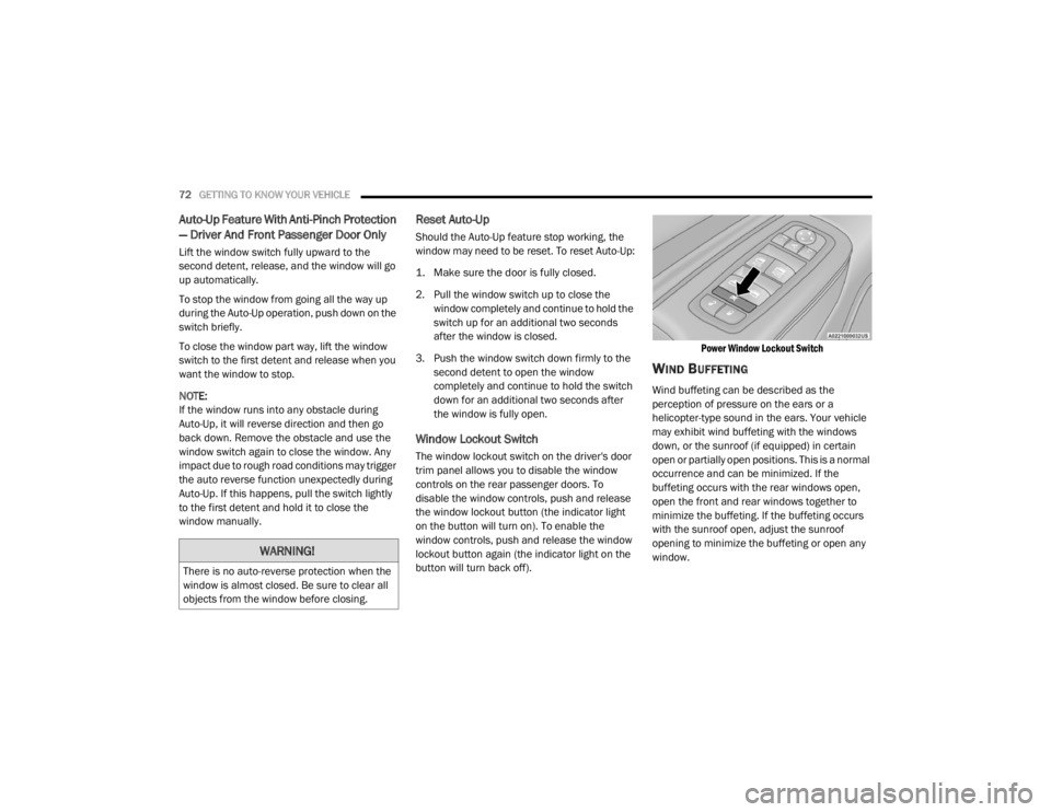
Window Lockout Switch
The window lockout switch on the driver's door
trim panel allows you to disable the window
controls on the rear passenger doors. To
disable the window controls, push and release
the window lockout button (the indicator light
on the button will turn on). To enable the
window controls, push and release the window
lockout button again (the indicator light on the
button will turn back off).
Power Window Lockout Switch
WIND BUFFETING
Wind buffeting can be described as the
perception of pressure on the ears or a
helicopter-type sound in the ears. Your vehicle
may exhibit wind buffeting with the windows
down, or the sunroof (if equipped) in certain
open or partially open positions. This is a normal
occurrence and can be minimized. If the
buffeting occurs with the rear windows open,
open the front and rear windows together to
minimize the buffeting. If the buffeting occurs
with the sunroof open, adjust the sunroof
opening to minimize the buffeting or open any
window.
WARNING!
There is no auto-reverse protection when the
window is almost closed. Be sure to clear all
objects from the window before closing.
20_WD_OM_EN_USC_t.book Page 72
Page 78 of 464
76GETTING TO KNOW YOUR VEHICLE
NOTE:
When using the liftgate button on the key fob
to open the liftgate while the vehicle is
locked, only the liftgate will unlock leaving
the other doors to remain locked. Closing the
liftgate will not re-lock the liftgate. The lock
button on the key fob, or the Passive Entry
lock button must be pushed to re-lock.
When using the Passive Entry button to open
the liftgate, and the vehicle doors unlock
(if “Unlock All Doors 1st Press” is selected in
the Passive Entry settings), the liftgate and
vehicle doors must be locked using the lock
button on the key fob, the Passive Entry lock
button, or the lock buttons on the interior
front door panels.
The power liftgate may also be opened or closed
by pushing the liftgate button located on the
front overhead console. If the liftgate is fully
open, the liftgate can be closed by pushing the
liftgate button located on left rear trim panel,
near the liftgate opening. If the liftgate is in
motion, pushing the liftgate button located on
left rear trim panel will reverse the liftgate. When the liftgate button on the key fob is
pushed two times, the turn signals will flash to
signal that the liftgate is opening or closing
(if "Flash Lamps with Lock" is enabled in the
Uconnect settings), and the liftgate chime will
be audible. Refer to "Uconnect Settings" in
"Multimedia” for further information.
NOTE:In the event of a power malfunction to the lift
-
gate, an emergency liftgate latch release can
be used to open the liftgate. The emergency
liftgate latch release can be accessed
through a snap-in cover located on the lift-
gate trim panel.
If liftgate is left open for an extended period
of time, the liftgate may need to be closed
manually to reset power liftgate functionality. NOTE:
The power liftgate buttons will not operate if
the vehicle is in gear or the vehicle speed is
above 0 mph (0 km/h).
The power liftgate will not operate in
temperatures below −22°F (−30°C) or
temperatures above 150°F (65°C). Be sure
to remove any buildup of snow or ice from the
liftgate before pushing any of the power lift
-
gate switches.
If anything obstructs the power liftgate while
it is closing or opening, the liftgate will auto -
matically reverse to the closed or open posi -
tion, provided it meets sufficient resistance.
There are also pinch sensors attached to the
side of the liftgate. Light pressure anywhere
along these strips will cause the liftgate to
return to the open position.
If the liftgate is not fully open, push the lift -
gate button on the key fob twice to operate
the liftgate.WARNING!
During power operation, personal injury or
cargo damage may occur. Ensure the liftgate
travel path is clear. Make sure the liftgate is
closed and latched before driving away.
20_WD_OM_EN_USC_t.book Page 76
Page 80 of 464
78GETTING TO KNOW YOUR VEHICLE
(Continued)
(Continued)
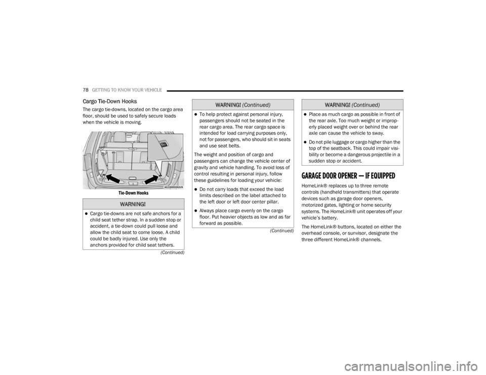
Cargo Tie-Down Hooks
The cargo tie-downs, located on the cargo area
floor, should be used to safely secure loads
when the vehicle is moving.
Tie-Down Hooks
GARAGE DOOR OPENER — IF EQUIPPED
HomeLink® replaces up to three remote
controls (handheld transmitters) that operate
devices such as garage door openers,
motorized gates, lighting or home security
systems. The HomeLink® unit operates off your
vehicle’s battery.
The HomeLink® buttons, located on either the
overhead console, or sunvisor, designate the
three different HomeLink® channels.
WARNING!
Cargo tie-downs are not safe anchors for a
child seat tether strap. In a sudden stop or
accident, a tie-down could pull loose and
allow the child seat to come loose. A child
could be badly injured. Use only the
anchors provided for child seat tethers.
To help protect against personal injury,
passengers should not be seated in the
rear cargo area. The rear cargo space is
intended for load carrying purposes only,
not for passengers, who should sit in seats
and use seat belts.
The weight and position of cargo and
passengers can change the vehicle center of
gravity and vehicle handling. To avoid loss of
control resulting in personal injury, follow
these guidelines for loading your vehicle:
Do not carry loads that exceed the load
limits described on the label attached to
the left door or left door center pillar.
Always place cargo evenly on the cargo
floor. Put heavier objects as low and as far
forward as possible.
WARNING! (Continued)
Place as much cargo as possible in front of
the rear axle. Too much weight or improp -
erly placed weight over or behind the rear
axle can cause the vehicle to sway.
Do not pile luggage or cargo higher than the
top of the seatback. This could impair visi-
bility or become a dangerous projectile in a
sudden stop or accident.
WARNING! (Continued)
20_WD_OM_EN_USC_t.book Page 78