buttons DODGE DURANGO 2021 User Guide
[x] Cancel search | Manufacturer: DODGE, Model Year: 2021, Model line: DURANGO, Model: DODGE DURANGO 2021Pages: 340, PDF Size: 20.38 MB
Page 49 of 340
GETTING TO KNOW YOUR VEHICLE47
PROGRAMMING HOMELINK® TO A
M
ISCELLANEOUS DEVICE
Refer to “Programming HomeLink® To A Garage
Door Opener” for the procedure on how to program
HomeLink® to a miscellaneous device, as it
follows the same procedure. Be sure to determine
if the device has a rolling code, or non-rolling code
before beginning the programming process.
NOTE:Canadian Radio Frequency (RF) laws require trans -
mitter signals to time-out (or quit) after several
seconds of transmission, which may not be long
enough for HomeLink® to pick up the signal during
programming. Similar to this Canadian law, some
U.S. gate operators are designed to time-out in the
same manner. The procedure may need to be
performed multiple times to successfully pair the
device to your HomeLink® buttons.
REPROGRAMMING A SINGLE
H
OMELINK® BUTTON
To reprogram a single HomeLink® button that has
been previously trained, without erasing all the
channels, follow the procedure below. Be sure to
determine whether the new device you want to
program the HomeLink® button to has a rolling
code, or non-rolling code.
1. Place the ignition to the ON/RUN position,
without starting the engine.
2. Push and hold the desired HomeLink® button until the HomeLink® indicator light begins to
flash after 20 seconds. Do not release the
button.
3. Without releasing the button , proceed with
Step 2 in “Programming HomeLink® To A
Garage Door Opener” and follow all remaining
steps.
CANADIAN/GATE OPERATOR
P
ROGRAMMING
For programming transmitters in Canada/United
States that require the transmitter signals to
“time-out” after several seconds of transmission:
Canadian Radio Frequency (RF) laws require
transmitter signals to time-out (or quit) after
several seconds of transmission, which may not be
long enough for HomeLink® to pick up the signal
during programming. Similar to this Canadian law,
some U.S. gate operators are designed to time-out
in the same manner.
It may be helpful to unplug the device during the
cycling process to prevent possible overheating of
the garage door or gate motor.
1. Place the ignition in the ON/RUN position.
NOTE:For vehicles equipped with Keyless Enter ‘n Go™,
place the ignition in the RUN position with the
engine on. Make sure while programming
HomeLink® with the engine on that your vehicle is
outside of your garage, or that the garage door
remains open at all times.
WARNING!
Your motorized door or gate will open and
close while you are programming the universal
transceiver. Do not program the transceiver if
people or pets are in the path of the door or
gate.
Do not run your vehicle in a closed garage or
confined area while programming the trans -
ceiver. Exhaust gas from your vehicle contains
Carbon Monoxide (CO) which is odorless and
colorless. Carbon Monoxide is poisonous
when inhaled and can cause you and others to
be severely injured or killed.
2
21_WD_OM_EN_USC_t.book Page 47
Page 50 of 340
48GETTING TO KNOW YOUR VEHICLE
2. Place the hand-held transmitter 1 to 3 inches (3 to 8 cm) away from the HomeLink® button
you wish to program while keeping the
HomeLink® indicator light in view.
3. Continue to push and hold the HomeLink® button while you push and release (cycle) your
hand-held transmitter every two seconds until
HomeLink® has successfully accepted the
frequency signal. The indicator light will flash
slowly and then rapidly when fully trained.
4. Watch for the HomeLink® indicator to change flash rates. When it changes, it is
programmed. It may take up to 30 seconds or
longer in rare cases. The garage door may
open and close while you are programming.
5. Push and hold the programmed HomeLink® button and observe the indicator light.
NOTE:
If the indicator light stays on constantly,
programming is complete and the garage
door/device should activate when the
HomeLink® button is pushed.
To program the two remaining HomeLink®
buttons, repeat each step for each
remaining button. DO NOT erase the chan -
nels.
If you unplugged the garage door opener/device
for programming, plug it back in at this time.
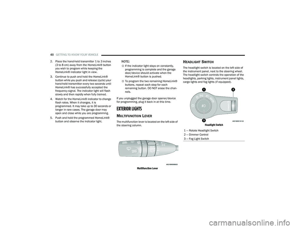
EXTERIOR LIGHTS
MULTIFUNCTION LEVER
The multifunction lever is located on the left side of
the steering column.
Multifunction Lever
HEADLIGHT SWITCH
The headlight switch is located on the left side of
the instrument panel, next to the steering wheel.
The headlight switch controls the operation of the
headlights, parking lights, instrument panel lights,
cargo lights and fog lights (if equipped).
Headlight Switch
1 — Rotate Headlight Switch
2 — Dimmer Control
3 — Fog Light Switch
21_WD_OM_EN_USC_t.book Page 48
Page 54 of 340
52GETTING TO KNOW YOUR VEHICLE
AUTOMATIC HEADLIGHT LEVELING —
I
F EQUIPPED
This feature prevents the headlights from
interfering with the vision of oncoming drivers.
Headlight leveling automatically adjusts the height
of the headlight beam in reaction to changes in
vehicle pitch.
BATTERY SAVER
Timers are set to both the interior and exterior
lights to protect the life of your vehicle’s battery.
After 10 minutes, if the ignition is OFF and any door
is left open or the dimmer control is rotated all the
way up to the dome light on position, the interior
lights will automatically turn off.
NOTE:Battery saver mode is canceled if the ignition is ON.
If the headlights remain on while the ignition is
placed in the OFF position, the exterior lights will
automatically turn off after eight minutes. If the
headlights are turned on and left on for eight
minutes while the ignition is OFF, the exterior lights
will automatically turn off.
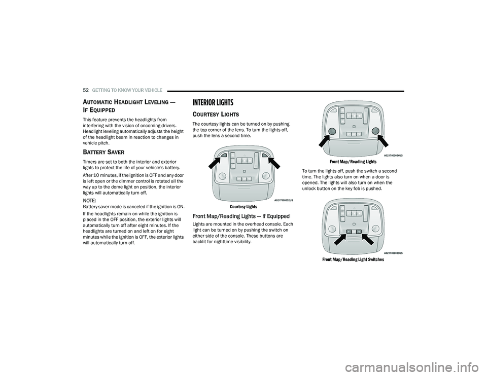
INTERIOR LIGHTS
COURTESY LIGHTS
The courtesy lights can be turned on by pushing
the top corner of the lens. To turn the lights off,
push the lens a second time.
Courtesy Lights
Front Map/Reading Lights — If Equipped
Lights are mounted in the overhead console. Each
light can be turned on by pushing the switch on
either side of the console. These buttons are
backlit for nighttime visibility.
Front Map/Reading Lights
To turn the lights off, push the switch a second
time. The lights also turn on when a door is
opened. The lights will also turn on when the
unlock button on the key fob is pushed.
Front Map/Reading Light Switches
21_WD_OM_EN_USC_t.book Page 52
Page 59 of 340
GETTING TO KNOW YOUR VEHICLE57
Front Defrost Button
Press and release the touchscreen
button, or push and release the button
on the faceplate, to change the current
airflow setting to Defrost mode. The Front
Defrost indicator illuminates when the Front
Defrost is on. Air comes from the windshield and
side window demist outlets. When the defrost
button is selected, the blower level may increase.
Use Defrost mode with maximum temperature
settings for best windshield and side window
defrosting and defogging. When toggling the Front
Defrost mode button, the climate system will
return to the previous setting.
Rear Defrost Button
Press and release the button on the
touchscreen, or push and release the
button on the faceplate, to turn on the
rear window defroster and the heated
outside mirrors (if equipped). The Rear Defrost
indicator illuminates when the rear window
defroster is on. The rear window defroster
automatically turns off after 10 minutes.
Driver And Passenger Temperature
Buttons
These buttons provide the driver and passenger
with independent temperature control.
Push the Up button on the faceplate or
press and slide the temperature bar
towards the red arrow button on the
touchscreen for warmer temperature
settings. Push the Down button on the faceplate or
press and slide the temperature bar
towards the blue arrow button on the
touchscreen for cooler temperature
settings.
SYNC Button
Press the SYNC button on the
touchscreen to toggle the SYNC feature
on/off. The SYNC indicator illuminates
when SYNC is on. SYNC is used to
synchronize the front passenger temperature and
rear passenger temperature, mode, and blower
settings with the driver temperature, mode, and
blower settings. Changing the front passenger
temperature or rear passenger temperature,
mode, and blower settings while in SYNC will
automatically exit this feature.
NOTE:The SYNC setting is only available on the touch -
screen.
Blower Control
Blower Control is used to regulate the
amount of air forced through the Climate
Control system. There are seven blower
speeds available. Adjusting the blower
will cause automatic mode to switch to manual
operation. The speeds can be selected using either
the blower control knob on the faceplate or the
buttons on the touchscreen.
CAUTION!
Failure to follow these cautions can cause
damage to the heating elements:
Use care when washing the inside of the rear
window. Do not use abrasive window cleaners
on the interior surface of the window. Use a
soft cloth and a mild washing solution, wiping
parallel to the heating elements. Labels can
be peeled off after soaking with warm water.
Do not use scrapers, sharp instruments, or
abrasive window cleaners on the interior
surface of the window.
Keep all objects a safe distance from the
window.
2
21_WD_OM_EN_USC_t.book Page 57
Page 60 of 340
58GETTING TO KNOW YOUR VEHICLE
Faceplate: The blower speed increases as you
turn the blower control knob clockwise from the
lowest blower setting. The blower speed
decreases as you turn the blower control knob
counterclockwise.
Touchscreen: Use the small blower icon to
reduce the blower setting and the large blower
icon to increase the blower setting. Blower
speed can also be selected by pressing the
blower bar area between the icons.
Mode Control
Select Mode by pressing the Mode
button on the faceplate, or one of the
Mode buttons on the touchscreen to
change the airflow distribution mode.
The airflow distribution mode can be adjusted so
air comes from the instrument panel outlets, floor
outlets, defrost outlets and demist outlets.
Panel Mode
Air comes from the outlets in the
instrument panel. Each of these outlets
can be individually adjusted to direct the
flow of air. The air vanes of the center
outlets and outboard outlets can be moved up and
down or side to side to regulate airflow direction.
There is a shut-off wheel located below the air
vanes to shut off or adjust the amount of airflow
from these outlets.
Bi-Level Mode
Air comes from the instrument panel
outlets and floor outlets. A slight amount
of air is directed through the defrost and
side window demister outlets.
NOTE:Bi-Level mode is designed under comfort condi -
tions to provide cooler air out of the panel outlets
and warmer air from the floor outlets.
Floor Mode
Air comes from the floor outlets. A slight
amount of air is directed through the
defrost and side window demister
outlets.
Mix Mode
Air is directed through the floor, defrost,
and side window demister outlets. This
setting works best in cold or snowy
conditions that require extra heat to the
windshield. This setting is good for maintaining
comfort while reducing moisture on the
windshield.
Climate Control OFF Button
Press and release this button to turn the
Climate Control ON/OFF.
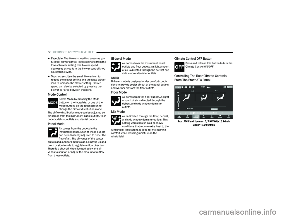
Controlling The Rear Climate Controls
From The Front ATC Panel
Front ATC Panel Uconnect 5/5 NAV With 10.1–inch
Display Rear Controls
21_WD_OM_EN_USC_t.book Page 58
Page 61 of 340
GETTING TO KNOW YOUR VEHICLE59
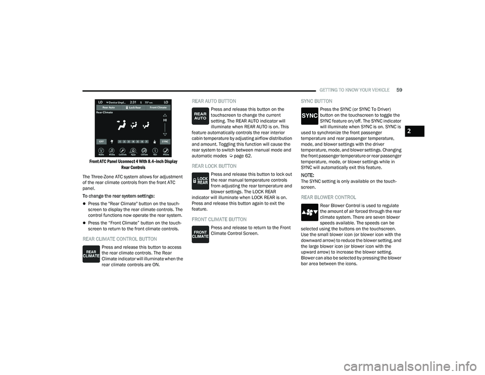
Front ATC Panel Uconnect 4 With 8.4–inch Display Rear Controls
The Three-Zone ATC system allows for adjustment
of the rear climate controls from the front ATC
panel.
To change the rear system settings:
Press the "Rear Climate" button on the touch -
screen to display the rear climate controls. The
control functions now operate the rear system.
Press the “Front Climate” button on the touch-
screen to return to the front climate controls.
REAR CLIMATE CONTROL BUTTON
Press and release this button to access
the rear climate controls. The Rear
Climate indicator will illuminate when the
rear climate controls are ON.
REAR AUTO BUTTON
Press and release this button on the
touchscreen to change the current
setting. The REAR AUTO indicator will
illuminate when REAR AUTO is on. This
feature automatically controls the rear interior
cabin temperature by adjusting airflow distribution
and amount. Toggling this function will cause the
rear system to switch between manual mode and
automatic modes Ú page 62.
REAR LOCK BUTTON
Press and release this button to lock out
the rear manual temperature controls
from adjusting the rear temperature and
blower settings. The LOCK REAR
indicator will illuminate when LOCK REAR is on.
Press and release this button again to exit the
feature.
FRONT CLIMATE BUTTON
Press and release to return to the Front
Climate Control Screen.
SYNC BUTTON
Press the SYNC (or SYNC To Driver)
button on the touchscreen to toggle the
SYNC feature on/off. The SYNC indicator
will illuminate when SYNC is on. SYNC is
used to synchronize the front passenger
temperature and rear passenger temperature,
mode, and blower settings with the driver
temperature, mode, and blower settings. Changing
the front passenger temperature or rear passenger
temperature, mode, or blower settings while in
SYNC will automatically exit this feature.
NOTE:The SYNC setting is only available on the touch -
screen.
REAR BLOWER CONTROL
Rear Blower Control is used to regulate
the amount of air forced through the rear
climate system. There are seven blower
speeds available. The speeds can be
selected using the buttons on the touchscreen.
Use the small blower icon (or blower icon with the
downward arrow) to reduce the blower setting, and
the large blower icon (or blower icon with the
upward arrow) to increase the blower setting.
Blower can also be selected by pressing the blower
bar area between the icons.
2
21_WD_OM_EN_USC_t.book Page 59
Page 62 of 340
60GETTING TO KNOW YOUR VEHICLE
REAR MODE CONTROL
Select Mode by pressing one of the Mode
buttons on the touchscreen to change
the airflow distribution mode. The rear
airflow distribution mode can be
adjusted so air comes from the headliner outlets,
the floor outlets or both.
HEADLINER MODE
Air comes from the outlets in the
headliner. Each of these outlets can be
individually adjusted to direct the flow of
air. Moving the air vanes of the outlets to
one side shuts off the airflow.
BI-LEVEL MODE
Press this button on the touchscreen to
change the air distribution mode to
Bi-Level Mode. In Bi-Level Mode, air
comes from both the headliner outlets
and the floor outlets.
NOTE:In many temperature positions, the Bi-Level mode
is designed to provide cooler air out of the head -
liner outlets and warmer air from the floor outlets.
FLOOR MODE
Press this button on the touchscreen to
change the air distribution mode to Floor
Mode. In Floor Mode, air comes from the
floor outlets.
REAR CLIMATE CONTROL OFF BUTTON
To manually set the rear blower controls
to off, press the Rear Climate Control/
Blower Off button.
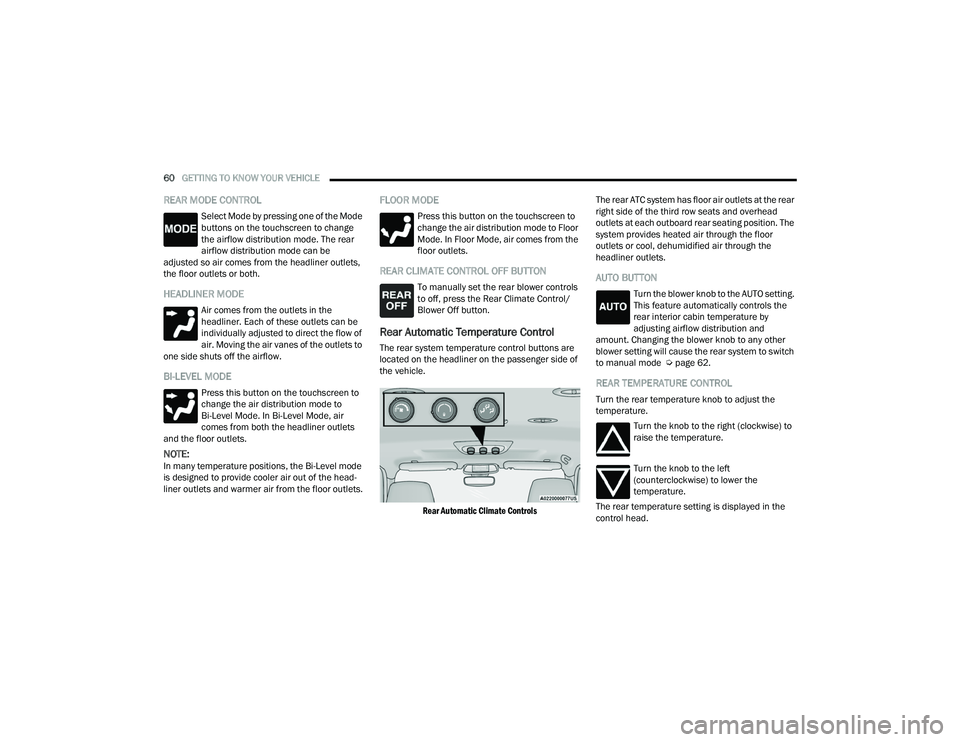
Rear Automatic Temperature Control
The rear system temperature control buttons are
located on the headliner on the passenger side of
the vehicle.
Rear Automatic Climate Controls
The rear ATC system has floor air outlets at the rear
right side of the third row seats and overhead
outlets at each outboard rear seating position. The
system provides heated air through the floor
outlets or cool, dehumidified air through the
headliner outlets.
AUTO BUTTON
Turn the blower knob to the AUTO setting.
This feature automatically controls the
rear interior cabin temperature by
adjusting airflow distribution and
amount. Changing the blower knob to any other
blower setting will cause the rear system to switch
to manual mode Ú page 62.
REAR TEMPERATURE CONTROL
Turn the rear temperature knob to adjust the
temperature.
Turn the knob to the right (clockwise) to
raise the temperature.
Turn the knob to the left
(counterclockwise) to lower the
temperature.
The rear temperature setting is displayed in the
control head.
21_WD_OM_EN_USC_t.book Page 60
Page 69 of 340
GETTING TO KNOW YOUR VEHICLE67
Rear Mini Center Console — If Equipped
An open storage area, or cubby bin with removable
liner, is located in the front of the console.
Console Cubby Bin
USB/AUX CONTROL
This feature allows an external USB device to be
plugged into the USB port.
Plugging in a smartphone device to a USB port may
activate Android Auto™ or Apple CarPlay®
features, if equipped. For further information, refer
to “Android Auto™” or “Apple CarPlay®” in the
Owner’s Manual Supplement.
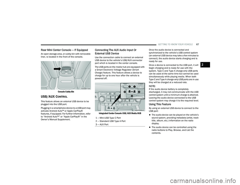
Connecting The AUX Audio Input Or
External USB Device
Use the connection cable to connect an external
USB device to the vehicle’s USB/AUX connector
port which is located in the center console.
The USB ports on the media hub are equipped with
a Smart Electronic Voltage Regulator (Smart
Charge) feature. This feature allows a device to
charge for up to one hour after the vehicle is
powered off.
Integrated Center Console USB/AUX Media HUB
Once the audio device is connected and
synchronized to the vehicle’s USB control system
(an external USB device may take a few minutes to
connect), the audio device starts charging and is
ready for use.
Once a device is connected to the USB port, it will
begin charging and is ready for use with the
system. Type C and Type A charge-only USB ports
can be used at the same time but cannot be used
simultaneously while playing media. When both
Type C and Type A charge-only USB ports are in use
they will be charged at a reduced rate.
NOTE:If the audio device battery is completely
discharged, it may not communicate with the USB
control system until a minimum charge is attained.
Leaving the audio device connected to the USB
control system may charge it to the required level.
Using This Feature
By using an external USB device to connect to the
USB port:
The audio device can be played on the vehicle’s
sound system, providing metadata (artist, track
title, album, etc.) information on the radio
display.
The audio device can be controlled using the
radio buttons to Play, Browse, and List the
contents.
1 — Mini-USB Type C Port
2 — Standard USB Type A Port
3 — AUX Port
2
21_WD_OM_EN_USC_t.book Page 67
Page 77 of 340
GETTING TO KNOW YOUR VEHICLE75
CLOSING THE HOOD
LIFTGATE
POWER LIFTGATE — IF EQUIPPED
The power liftgate may be opened by
pushing the liftgate release handle
Úpage 23 or by pushing the liftgate
button on the key fob. Push the liftgate
button on the key fob twice within five seconds to
open or close the power liftgate.
NOTE:
When using the liftgate button on the key fob to
open the liftgate while the vehicle is locked, only
the liftgate will unlock leaving the other doors to
remain locked. Closing the liftgate will not relock
the liftgate. The lock button on the key fob, or
the Passive Entry lock button must be pushed to
relock.
If the Passive Entry button is used to open the
liftgate and all the doors unlock, the liftgate and
vehicle doors must be locked again. Use the key
fob, Passive Entry lock button, or the power door
lock switches on the front door panels.
The power liftgate may also be opened or closed by
pushing the liftgate button located on the front
overhead console. If the liftgate is fully open, it can
be closed by pushing the liftgate button located on
the left rear trim panel. If the liftgate is in motion,
pushing the button again will reverse the liftgate.
When the liftgate button on the key fob is pushed
two times, the turn signals will flash to signal that
the liftgate is opening or closing (if Flash Lamps
with Lock is enabled in the Uconnect settings), and
the liftgate chime will be audible. The chime can be
turned on or off through the Uconnect Settings
Ú page 159.
NOTE:
In the event of a power malfunction to the lift -
gate, an emergency liftgate latch release can be
used to open the liftgate. The emergency liftgate
latch release can be accessed through a snap-in
cover located on the liftgate trim panel.
If liftgate is left open for an extended period of
time, the liftgate may need to be closed manu -
ally to reset power liftgate functionality.
NOTE:
The power liftgate buttons will not operate if the
vehicle is in gear or the vehicle speed is above
0 mph (0 km/h).
The power liftgate will not operate in tempera -
tures below −22°F (−30°C) or temperatures
above 150°F (65°C). Be sure to remove any
buildup of snow or ice from the liftgate before
pushing any of the power liftgate switches.
WARNING!
Be sure the hood is fully latched before driving
your vehicle. If the hood is not fully latched, it
could open when the vehicle is in motion and
block your vision. Failure to follow this warning
could result in serious injury or death.
CAUTION!
To prevent possible damage, do not slam the
hood to close it. Lower hood to approximately
12 inches (30 cm) and drop the hood to close.
Make sure hood is fully closed for both latches.
Never drive vehicle unless hood is fully closed,
with both latches engaged.
WARNING!
During power operation, personal injury or cargo
damage may occur. Ensure the liftgate travel
path is clear. Make sure the liftgate is closed
and latched before driving away.
2
21_WD_OM_EN_USC_t.book Page 75
Page 86 of 340
84GETTING TO KNOW YOUR INSTRUMENT PANEL
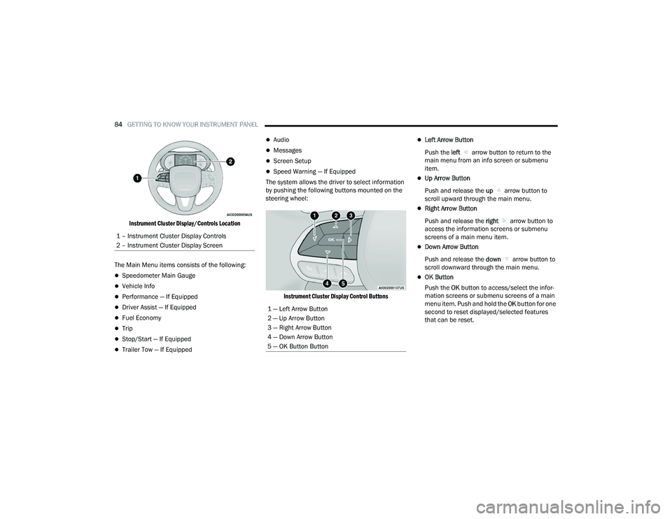
Instrument Cluster Display/Controls Location
The Main Menu items consists of the following:
Speedometer Main Gauge
Vehicle Info
Performance — If Equipped
Driver Assist — If Equipped
Fuel Economy
Trip
Stop/Start — If Equipped
Trailer Tow — If Equipped
Audio
Messages
Screen Setup
Speed Warning — If Equipped
The system allows the driver to select information
by pushing the following buttons mounted on the
steering wheel:
Instrument Cluster Display Control Buttons
Left Arrow Button
Push the left arrow button to return to the
main menu from an info screen or submenu
item.
Up Arrow Button
Push and release the up arrow button to
scroll upward through the main menu.
Right Arrow Button
Push and release the right arrow button to
access the information screens or submenu
screens of a main menu item.
Down Arrow Button
Push and release the down arrow button to
scroll downward through the main menu.
OK Button
Push the OK button to access/select the infor -
mation screens or submenu screens of a main
menu item. Push and hold the OK button for one
second to reset displayed/selected features
that can be reset.
1 – Instrument Cluster Display Controls
2 – Instrument Cluster Display Screen
1 — Left Arrow Button
2 — Up Arrow Button
3 — Right Arrow Button
4 — Down Arrow Button
5 — OK Button Button
21_WD_OM_EN_USC_t.book Page 84