ABS DODGE DURANGO 2021 Owners Manual
[x] Cancel search | Manufacturer: DODGE, Model Year: 2021, Model line: DURANGO, Model: DODGE DURANGO 2021Pages: 340, PDF Size: 20.38 MB
Page 7 of 340
5
TRAILER TOWING ................................................ 142 Common Towing Definitions ......................... 142Trailer Hitch Classification ............................ 145
Trailer Towing Weights
(Maximum Trailer Weight Ratings) ............ 145Trailer Hitch Receiver Cover Removal —
If Equipped..................................................... 146
Trailer And Tongue Weight ........................... 147
Towing Requirements .................................. 147
Towing Tips ................................................... 152
RECREATIONAL TOWING
(BEHIND MOTORHOME) ...................................... 153
Towing This Vehicle Behind Another
Vehicle............................................................ 153
Recreational Towing — Rear-Wheel
Drive Models.................................................. 153
Recreational Towing — All-Wheel Drive
Models (Single-Speed Transfer Case).......... 154
Recreational Towing — All-Wheel Drive
Models (Two-Speed Transfer Case) ............. 154
DRIVING TIPS ....................................................... 156
On-Road Driving Tips..................................... 156
Off-Road Driving Tips..................................... 157
MULTIMEDIA
UCONNECT SYSTEMS ........................................ 158
CYBERSECURITY ................................................ 158
UCONNECT SETTINGS ......................................... 159Customer Programmable Features.............. 159
STEERING WHEEL AUDIO CONTROLS .............. 178
Radio Operation ............................................ 178
Media Mode................................................... 178
UCONNECT REAR SEAT ENTERTAINMENT
(RSE) SYSTEM — IF EQUIPPED .......................... 178
Getting Started .............................................. 178
Dual Video Screen......................................... 179
Play A Blu-ray™ Disc...................................... 180
Play Video Games ......................................... 182
Important Notes For Dual Video Screen
System ........................................................... 182
Blu-ray™ Disc Player Remote Control .......... 183
Headphones Operation................................. 184
Controls.......................................................... 184Replacing The Headphone Batteries ........... 184Accessibility — If Equipped ........................... 184Stereo Headphone Lifetime Limited
Warranty ........................................................ 185
RADIO OPERATION AND MOBILE PHONES ..... 188
Regulatory And Safety Information .............. 188
SAFETY
SAFETY FEATURES .............................................. 189 Anti-Lock Brake System (ABS) ..................... 189Electronic Brake Control (EBC) System ...... 190
AUXILIARY DRIVING SYSTEMS .......................... 195
Blind Spot Monitoring (BSM) —
If Equipped .................................................... 195
Forward Collision Warning (FCW) With
Mitigation ....................................................... 199Tire Pressure Monitoring System
(TPMS) ........................................................... 201
OCCUPANT RESTRAINT SYSTEMS ................... 204
Occupant Restraint Systems Features ........ 204Important Safety Precautions ...................... 204
Seat Belt Systems ........................................ 205
Supplemental Restraint Systems (SRS) ...... 211Child Restraints ........................................... 223
SAFETY TIPS ...................................................... 239
Transporting Passengers.............................. 239
Transporting Pets ....................................... 239
Safety Checks You Should Make
Inside The Vehicle ........................................ 239
Periodic Safety Checks You Should
Make Outside The Vehicle ............................ 241
Exhaust Gas................................................... 241
Carbon Monoxide Warnings ....................... 242
21_WD_OM_EN_USC_t.book Page 5
Page 13 of 340
11
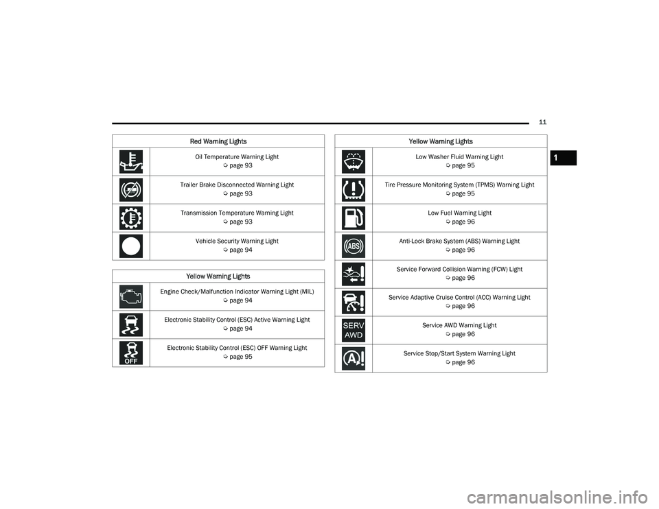
Oil Temperature Warning Light Úpage 93
Trailer Brake Disconnected Warning Light Úpage 93
Transmission Temperature Warning Light Úpage 93
Vehicle Security Warning Light Úpage 94
Yellow Warning Lights
Engine Check/Malfunction Indicator Warning Light (MIL)
Úpage 94
Electronic Stability Control (ESC) Active Warning Light Úpage 94
Electronic Stability Control (ESC) OFF Warning Light Úpage 95
Red Warning Lights
Low Washer Fluid Warning Light
Úpage 95
Tire Pressure Monitoring System (TPMS) Warning Light Úpage 95
Low Fuel Warning Light Úpage 96
Anti-Lock Brake System (ABS) Warning Light Úpage 96
Service Forward Collision Warning (FCW) Light Úpage 96
Service Adaptive Cruise Control (ACC) Warning Light Úpage 96
Service AWD Warning Light Úpage 96
Service Stop/Start System Warning Light Úpage 96
Yellow Warning Lights
1
21_WD_OM_EN_USC_t.book Page 11
Page 24 of 340
22GETTING TO KNOW YOUR VEHICLE
NOTE:
The driver's door key cylinder cannot arm or
disarm the Vehicle Security system. Use of the
door key cylinder when the alarm is armed will
sound the alarm when the door is opened.
The Vehicle Security system remains armed
when the power liftgate is opened using the lift -
gate button on the key fob. If someone enters
the vehicle through the liftgate and opens any
door from the inside, the alarm will sound.
If Passive Entry (if equipped) is used to unlock
the liftgate, the Vehicle Security system is
disarmed and the rest of the vehicle doors will
remain locked unless all doors are set to unlock
on first press within Uconnect Settings.
When the Vehicle Security system is armed, the
interior power door lock switches will not unlock
the doors.
The Vehicle Security system is designed to protect
your vehicle. However, you can create conditions
where the system will give you a false alarm. If one
of the previously described arming sequences has
occurred, the Vehicle Security system will arm
regardless of whether you are in the vehicle or not.
If you remain in the vehicle and open a door, the
alarm will sound. If this occurs, disarm the Vehicle
Security system. If the Vehicle Security system is armed and the
battery becomes disconnected, the Vehicle
Security system will remain armed when the
battery is reconnected; the exterior lights will flash,
and the horn will sound. If this occurs, disarm the
Vehicle Security system.
REARMING OF THE SYSTEM
If something triggers the alarm and no action is
taken to disarm it, the Vehicle Security system will
turn the horn off after a 29 second cycle (with five
seconds between cycles and up to eight cycles if
the trigger remains active) and then rearm itself.
SECURITY SYSTEM MANUAL OVERRIDE
The Vehicle Security system will not arm if you lock
the doors using the manual door lock.
TAMPER ALERT
If something has triggered the Vehicle Security
system in your absence, the horn will sound three
times and the exterior lights will blink three times
when you disarm the Vehicle Security system.
DOORS
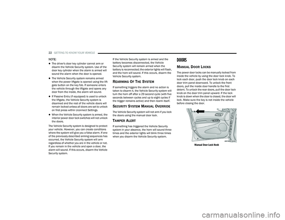
MANUAL DOOR LOCKS
The power door locks can be manually locked from
inside the vehicle by using the door lock knob. To
lock each door, push the door lock knob on each
door trim panel downward. To unlock the front
doors, pull the inside door handle to the first
detent. To unlock the rear doors, pull the door lock
knob on the door trim panel upward. If the lock
knob is down when the door is closed, the door will
lock. Make sure the key is not inside the vehicle
before closing the door.
Manual Door Lock Knob
21_WD_OM_EN_USC_t.book Page 22
Page 93 of 340
GETTING TO KNOW YOUR INSTRUMENT PANEL91
WARNING LIGHTS AND MESSAGES
The warning/indicator lights will illuminate in the
instrument panel together with a dedicated
message and/or acoustic signal when applicable.
These indications are indicative and precautionary
and as such must not be considered as exhaustive
and/or alternative to the information contained in
the Owner’s Manual, which you are advised to read
carefully in all cases. Always refer to the
information in this chapter in the event of a failure
indication. All active telltales will display first if
applicable. The system check menu may appear
different based upon equipment options and
current vehicle status. Some telltales are optional
and may not appear.
RED WARNING LIGHTS
Seat Belt Reminder Warning Light
This warning light indicates when the
driver or passenger seat belt is
unbuckled. When the ignition is first
placed in the ON/RUN or ACC/ON/RUN
position and if the driver’s seat belt is unbuckled,
a chime will sound and the light will turn on. When
driving, if the driver or front passenger seat belt
remains unbuckled, the Seat Belt Reminder Light
will flash or remain on continuously and a chime
will sound Ú page 204.
Air Bag Warning Light
This warning light will illuminate to
indicate a fault with the air bag, and will
turn on for four to eight seconds as a bulb
check when the ignition is placed in the
ON/RUN or ACC/ON/RUN position. This light will
illuminate with a single chime when a fault with the
air bag has been detected, it will stay on until the
fault is cleared. If the light is either not on during
startup, stays on, or turns on while driving, have
the system inspected at an authorized dealer as
soon as possible.
Brake Warning Light
This warning light monitors various brake
functions, including brake fluid level and
parking brake application. If the brake
light turns on it may indicate that the
parking brake is applied, that the brake fluid level
is low, or that there is a problem with the Anti-Lock
Brake System reservoir.
If the light remains on when the parking brake has
been disengaged, and the fluid level is at the full
mark on the master cylinder reservoir, it indicates
a possible brake hydraulic system malfunction or
that a problem with the Brake Booster has been
detected by the Anti-Lock Brake System (ABS) /
Electronic Stability Control (ESC) system. In this case, the light will remain on until the condition has
been corrected. If the problem is related to the
brake booster, the ABS pump will run when
applying the brake, and a brake pedal pulsation
may be felt during each stop.
The dual brake system provides a reserve braking
capacity in the event of a failure to a portion of the
hydraulic system. A leak in either half of the dual
brake system is indicated by the Brake Warning
Light, which will turn on when the brake fluid level
in the master cylinder has dropped below a
specified level.
The light will remain on until the cause is corrected.NOTE:The light may flash momentarily during sharp
cornering maneuvers, which change fluid level
conditions. The vehicle should have service
performed, and the brake fluid level checked.
If brake failure is indicated, immediate repair is
necessary.
WARNING!
Driving a vehicle with the red brake light on is
dangerous. Part of the brake system may have
failed. It will take longer to stop the vehicle. You
could have a collision. Have the vehicle checked
immediately.
3
21_WD_OM_EN_USC_t.book Page 91
Page 94 of 340
92GETTING TO KNOW YOUR INSTRUMENT PANEL
Vehicles equipped with the Anti-Lock Brake System
(ABS) are also equipped with Electronic Brake
Force Distribution (EBD). In the event of an EBD
failure, the Brake Warning Light will turn on along
with the ABS Light. Immediate repair to the ABS
system is required.
Operation of the Brake Warning Light can be
checked by turning the ignition switch from the OFF
position to the ON/RUN position. The light should
illuminate for approximately two seconds. The light
should then turn off unless the parking brake is
applied or a brake fault is detected. If the light does
not illuminate, have the light inspected by an
authorized dealer.
The light also will turn on when the parking brake
is applied with the ignition switch in the ON/RUN
position.
NOTE:This light shows only that the parking brake is
applied. It does not show the degree of brake appli -
cation.
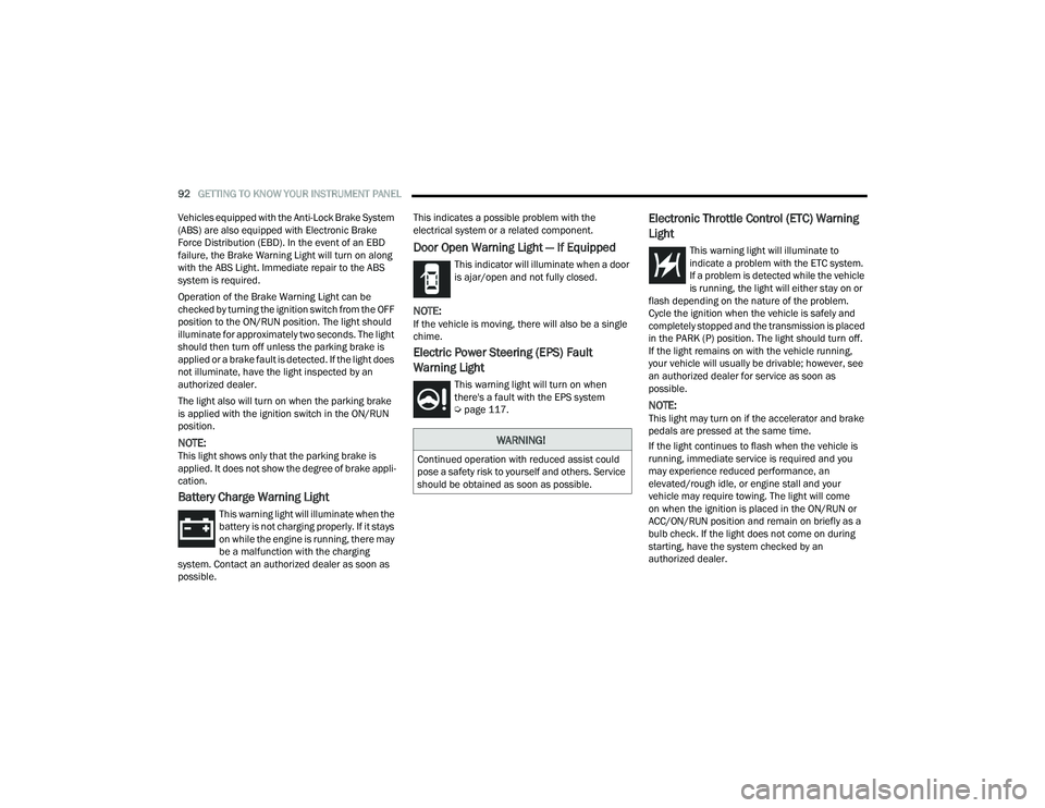
Battery Charge Warning Light
This warning light will illuminate when the
battery is not charging properly. If it stays
on while the engine is running, there may
be a malfunction with the charging
system. Contact an authorized dealer as soon as
possible. This indicates a possible problem with the
electrical system or a related component.
Door Open Warning Light — If Equipped
This indicator will illuminate when a door
is ajar/open and not fully closed.
NOTE:If the vehicle is moving, there will also be a single
chime.
Electric Power Steering (EPS) Fault
Warning Light
This warning light will turn on when
there's a fault with the EPS system
Ú
page 117.
Electronic Throttle Control (ETC) Warning
Light
This warning light will illuminate to
indicate a problem with the ETC system.
If a problem is detected while the vehicle
is running, the light will either stay on or
flash depending on the nature of the problem.
Cycle the ignition when the vehicle is safely and
completely stopped and the transmission is placed
in the PARK (P) position. The light should turn off.
If the light remains on with the vehicle running,
your vehicle will usually be drivable; however, see
an authorized dealer for service as soon as
possible.
NOTE:This light may turn on if the accelerator and brake
pedals are pressed at the same time.
If the light continues to flash when the vehicle is
running, immediate service is required and you
may experience reduced performance, an
elevated/rough idle, or engine stall and your
vehicle may require towing. The light will come
on when the ignition is placed in the ON/RUN or
ACC/ON/RUN position and remain on briefly as a
bulb check. If the light does not come on during
starting, have the system checked by an
authorized dealer.
WARNING!
Continued operation with reduced assist could
pose a safety risk to yourself and others. Service
should be obtained as soon as possible.
21_WD_OM_EN_USC_t.book Page 92
Page 98 of 340
96GETTING TO KNOW YOUR INSTRUMENT PANEL
When the malfunction indicator is illuminated, the
system may not be able to detect or signal low tire
pressure as intended. TPMS malfunctions may
occur for a variety of reasons, including the
installation of replacement or alternate tires or
wheels on the vehicle that prevent the TPMS from
functioning properly. Always check the TPMS
malfunction telltale after replacing one or more
tires or wheels on your vehicle to ensure that the
replacement or alternate tires and wheels allow
the TPMS to continue to function properly.
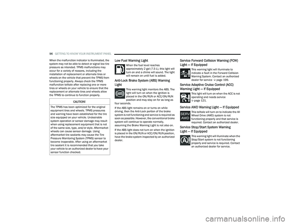
Low Fuel Warning Light
When the fuel level reaches
approximately 2 gal (7.5 L), this light will
turn on and a chime will sound. The light
will remain on until fuel is added.
Anti-Lock Brake System (ABS) Warning
Light
This warning light monitors the ABS. The
light will turn on when the ignition is
placed in the ON/RUN or ACC/ON/RUN
position and may stay on for as long as
four seconds.
If the ABS light remains on or turns on while
driving, then the Anti-Lock portion of the brake
system is not functioning and service is required as
soon as possible. However, the conventional brake
system will continue to operate normally,
assuming the Brake Warning Light is not also on.
If the ABS light does not turn on when the ignition
is placed in the ON/RUN or ACC/ON/RUN position,
have the brake system inspected by an authorized
dealer.
Service Forward Collision Warning (FCW)
Light — If Equipped
This warning light will illuminate to
indicate a fault in the Forward Collision
Warning System. Contact an authorized
dealer for service Ú page 199.
Service Adaptive Cruise Control (ACC)
Warning Light — If Equipped
This light will turn on when the ACC is not
operating and needs service
Úpage 121.
Service AWD Warning Light — If Equipped
This telltale will turn on to indicate the All
Wheel Drive (AWD) system is not
functioning properly and that service is
required. Contact an authorized dealer.
Service Stop/Start System Warning
Light — If Equipped
This warning light will illuminate when the
Stop/Start system is not functioning
properly and service is required. Contact
an authorized dealer for service.
CAUTION!
The TPMS has been optimized for the original
equipment tires and wheels. TPMS pressures
and warning have been established for the tire
size equipped on your vehicle. Undesirable
system operation or sensor damage may result
when using replacement equipment that is not
of the same size, type, and/or style. Aftermarket
wheels can cause sensor damage. Using
aftermarket tire sealants may cause the Tire
Pressure Monitoring System (TPMS) sensor to
become inoperable. After using an aftermarket
tire sealant it is recommended that you take
your vehicle to an authorized dealer to have your
sensor function checked.
21_WD_OM_EN_USC_t.book Page 96
Page 114 of 340
112STARTING AND OPERATING
If a requested downshift would cause the
engine to over-speed, that shift will not occur.
The system will ignore attempts to upshift at too
low of a vehicle speed.
Holding the (-) paddle pressed, or holding the
gear selector in the (-) position, will downshift
the transmission to the lowest gear possible at
the current speed.
Transmission shifting will be more noticeable
when AutoStick is enabled.
The system may revert to automatic shift mode
if a fault or overheat condition is detected.
To disengage AutoStick mode, return the gear
selector to the DRIVE (D) position, or press and
hold the (+) shift paddle until "D" is indicated in the
instrument cluster. You can shift in or out of
AutoStick mode at any time without taking your
foot off the accelerator pedal.
SPORT MODE — IF EQUIPPED
Your vehicle is equipped with a SPORT Mode
feature. The engine, transmission, and steering
systems are all set to their SPORT settings. SPORT
Mode will provide improved throttle response and
modified transmission shift points for an enhanced
driving experience, as well as greater amount of
steering feel. This mode may be activated and
deactivated by pushing the SPORT button on the
instrument panel switch bank.
ALL-WHEEL DRIVE OPERATION
SINGLE-SPEED OPERATING
I
NSTRUCTIONS/PRECAUTIONS —
I
F EQUIPPED
This system contains a single-speed (HI range only)
transfer case, which provides convenient full-time
All-Wheel Drive (AWD). No driver interaction is
required. The Brake Traction Control (BTC) System,
which combines standard ABS and Traction
Control, provides resistance to any wheel that is
slipping to allow additional torque transfer to
wheels with traction.
NOTE:This system is not appropriate for conditions where
AWD Low is recommended Ú page 157.
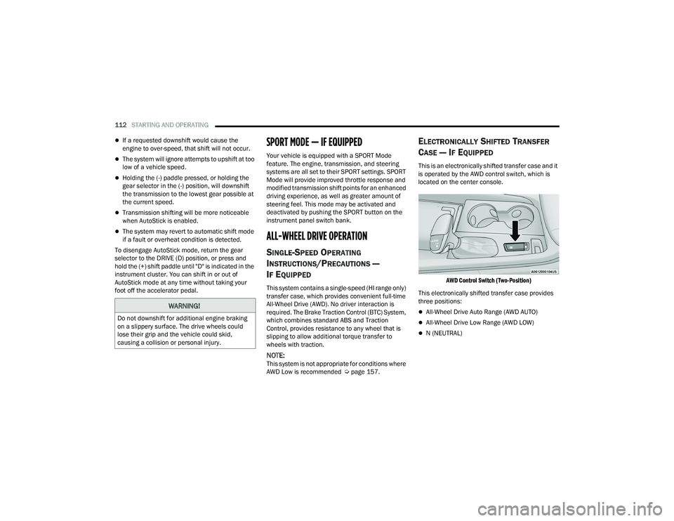
ELECTRONICALLY SHIFTED TRANSFER
C
ASE — IF EQUIPPED
This is an electronically shifted transfer case and it
is operated by the AWD control switch, which is
located on the center console.
AWD Control Switch (Two-Position)
This electronically shifted transfer case provides
three positions:
All-Wheel Drive Auto Range (AWD AUTO)
All-Wheel Drive Low Range (AWD LOW)
N (NEUTRAL)
WARNING!
Do not downshift for additional engine braking
on a slippery surface. The drive wheels could
lose their grip and the vehicle could skid,
causing a collision or personal injury.
21_WD_OM_EN_USC_t.book Page 112
Page 118 of 340
116STARTING AND OPERATING
Track usage results in increased operating
temperatures of the engine, transmission, drive -
line and brake system. This may affect Noise
Vibration Harshness (NVH) countermeasures
designed into your vehicle. New components
may need to be installed to return the system to
the original NVH performance.
Tire pressure:
Recommended tire pressure of 33 psi
(230 kPa) when tires are cold, or below
42 psi (290 kPa) when hot.
NOTE:It is recommended that you target below 42 psi
(290 kPa) when tires are hot at the conclusion of
each track session. Starting at 33 psi (230 kPa)
cold and adjusting based on ambient and track
conditions is recommended. Tire pressure can be
monitored via the instrument cluster display and
can assist with adjustments.
Track burnishing your brakes
To avoid “green lining fade” during track use, the
brake pads and rotors must have a thermal
burnish for factory-installed components or when
new brake friction components are installed:
1. Use one track session to burnish brakes by driving at 75% speed. Brake at approximately
0.60 - 0.80g max without Anti-Lock Brake
System (ABS) intervention.
2. Complete one lap in this manner until you start
smelling the brakes. Continue for another half
lap at speed, then complete a two lap
cooldown with minimal brake applications.
Ensure the brakes are not smoking. If they are,
complete another cooldown lap.
3. Getting the brakes to smoke is an indication that the brakes have overheated and may
negatively affect future track usage.
4. Allow vehicle to sit and cool for at least 30 minutes. If an infrared thermal gun is
available, allow rotors to cool to 200°F
(93.3°C) before returning to the track.
5. There should be a thin layer of ash when inspecting the brake pads. Having the ash
layer go more than half the thickness of the
pad material is a sign of an overly aggressive
burnish.
6. Occasionally, a second burnish session is required. If the brake pads begin to emit an
odor during the next track session, reduce
vehicle speed and braking deceleration rate to
burnish targets and follow steps 2-4. 7. New brake pads installed on old rotors require
a burnish. New rotors installed with old brake
pads should be burnished at the track or
driven for 300 miles (485 km) of city driving to
develop an adequate lining transfer layer on
the rotor surface prior to track use.
8. Rotors that pulsate during track use should be replaced.
NOTE:Resurfacing of the rotors is not recommended, as
it removes mass from the rotor, reducing its
thermal capacity. Resurfacing also thins the rotor
cheek, making it less robust and increasing the
likelihood of pulsation in further track use.
FUEL SAVER TECHNOLOGY 5.7L ONLY —
IF EQUIPPED
This feature offers improved fuel economy by
shutting off four of the engine's eight cylinders
during light load and cruise conditions. The system
is automatic with no driver inputs.
NOTE:This system may take some time to return to full
functionality after a battery disconnect.
21_WD_OM_EN_USC_t.book Page 116
Page 126 of 340
124STARTING AND OPERATING
NOTE:Fixed Speed Cruise Control cannot be set below
20 mph (32 km/h).
If either system is set when the vehicle speed is
above 20 mph (32 km/h), the set speed shall be
the current speed of the vehicle.
NOTE:
Keeping your foot on the accelerator pedal can
cause the vehicle to continue to accelerate
beyond the set speed. If this occurs, the
message “DRIVER OVERRIDE” will display in the
instrument cluster display.
If you continue to accelerate beyond the set
speed while ACC is enabled, the system will not
be controlling the distance between your vehicle
and the vehicle ahead. The vehicle speed will
only be determined by the position of the accel-
erator pedal.
To Cancel
The following conditions cancel the ACC or Fixed
Speed Cruise Control systems:
The brake pedal is applied
The CANC (cancel) button is pushed
The Anti-Lock Brake System (ABS) activates
The gear selector is removed from the DRIVE
position
The Electronic Stability Control/Traction Control
System (ESC/TCS) activates
The vehicle parking brake is applied
The Trailer Sway Control (TSC) activates
The driver switches ESC to Full Off mode
The braking temperature exceeds normal range
(overheated)
The following conditions will only cancel the ACC
system:
Driver seat belt is unbuckled at low speeds
Driver door is opened at low speeds
To Turn Off
The system will turn off and erase the set speed in
memory if:
The Adaptive Cruise Control (ACC) on/off button
is pushed
The Fixed Speed Cruise Control on/off button is
pushed
The ignition is placed in the OFF position
4WD Low is engaged
To Resume
If there is a set speed in memory, push the RES
(resume) button and remove your foot from the
accelerator pedal. The instrument cluster display
will show the last set speed.
Resume can be used at any speed above 20 mph
(32 km/h) when only Fixed Speed Cruise Control is
being used.
Resume can be used at any speed above 0 mph
(0 km/h) when ACC is active.
NOTE:
While in ACC mode when the vehicle comes to a
complete stop longer than two seconds, the
system will cancel. The driver will have to apply
the brakes to keep the vehicle at a standstill.
ACC cannot be resumed if there is a stationary
vehicle in front of your vehicle in close proximity.
WARNING!
The Resume function should only be used if
traffic and road conditions permit. Resuming a
set speed that is too high or too low for
prevailing traffic and road conditions could
cause the vehicle to accelerate or decelerate too
sharply for safe operation. Failure to follow these
warnings can result in a collision and death or
serious personal injury.
21_WD_OM_EN_USC_t.book Page 124
Page 148 of 340

146STARTING AND OPERATING
NOTE:The trailer tongue weight must be considered as
part of the combined weight of occupants and
cargo, and should never exceed the weight refer -
enced on the Tire and Loading Information placard
Ú page 295. The addition of passengers and cargo
may require reducing trailer tongue load and Gross
Trailer Weight (GTW).
TRAILER HITCH RECEIVER COVER
R
EMOVAL — IF EQUIPPED
Your vehicle may be equipped with a trailer hitch
receiver cover, this must be removed to access the
trailer hitch receiver (if equipped). This cover is
located at the bottom center of the rear fascia/
bumper.
1. Turn the two locking retainers located at the
bottom of the hitch receiver cover a quarter
turn counterclockwise and pull bottom of the
hitch receiver cover outward (towards you).
Hitch Receiver Cover
2. Pull the bottom of the cover outward (towards you) then downwards to disengage the tabs
located at the top of the hitch receiver cover to
remove.
Hitch Receiver Cover
To reinstall the cover after towing, repeat the
procedure in reverse order.
NOTE:Be sure to engage all tabs of the hitch receiver
cover in the bumper fascia prior to installation.
1 — Hitch Receiver Cover
2 — Locking Retainers
21_WD_OM_EN_USC_t.book Page 146