brake sensor DODGE DURANGO 2021 Owners Manual
[x] Cancel search | Manufacturer: DODGE, Model Year: 2021, Model line: DURANGO, Model: DODGE DURANGO 2021Pages: 340, PDF Size: 20.38 MB
Page 6 of 340
4
STARTING AND OPERATING
STARTING THE ENGINE ....................................... 101
Automatic Transmission ............................... 101
Normal Starting ............................................ 101
AutoPark ........................................................ 102If Engine Fails To Start ................................. 103Cold Weather Operation
(Below –22°F Or −30°C) ............................ 104
After Starting.................................................. 104
ENGINE BLOCK HEATER — IF EQUIPPED ......... 104
ENGINE BREAK-IN RECOMMENDATIONS ........ 104
PARKING BRAKE ................................................ 105
AUTOMATIC TRANSMISSION ........................... 106 Ignition Park Interlock ................................... 107Brake Transmission Shift Interlock (BTSI)
System ........................................................... 107Fuel Economy (ECO) Mode ........................... 107
8-Speed Automatic Transmission ................ 108
SPORT MODE — IF EQUIPPED ............................ 112
ALL-WHEEL DRIVE OPERATION .........................112
Single-Speed Operating Instructions/
Precautions — If Equipped ........................... 112
Electronically Shifted Transfer Case —
If Equipped..................................................... 112
Shifting Procedure......................................... 114 TOW N GO — IF EQUIPPED ................................. 115
Guidelines For Track Use.............................. 115
FUEL SAVER TECHNOLOGY 5.7L ONLY —
IF EQUIPPED ........................................................ 116
POWER STEERING .............................................. 117
STOP/START SYSTEM — IF EQUIPPED ............. 117
Autostop Mode .............................................. 117
Possible Reasons The Engine Does Not
Autostop......................................................... 118
To Start The Engine While In Autostop
Mode .............................................................. 118
To Manually Turn Off The
Stop/Start System......................................... 118
To Manually Turn On The Stop/Start
System ........................................................... 119
System Malfunction ...................................... 119
CRUISE CONTROL SYSTEMS —
IF EQUIPPED ....................................................... 119
Cruise Control — If Equipped ....................... 119
Adaptive Cruise Control (ACC) —
If Equipped .................................................. 121 PARKSENSE FRONT/REAR PARK ASSIST
SYSTEM — IF EQUIPPED .................................... 130
ParkSense Sensors ....................................... 131
ParkSense Display ........................................ 131
ParkSense Warning Display ......................... 134
Enabling And Disabling ParkSense.............. 134
Operation With A Trailer................................ 134Service The ParkSense Park Assist
System ........................................................... 135
Cleaning The ParkSense System ................. 135
ParkSense System Usage Precautions........ 135
LANESENSE — IF EQUIPPED .............................. 136
LaneSense Operation ................................... 136
Turning LaneSense On Or Off....................... 137
LaneSense Warning Message...................... 137
Changing LaneSense Status ........................ 139
PARKVIEW REAR BACK UP CAMERA .............. 139
REFUELING THE VEHICLE ................................... 140
VEHICLE LOADING ............................................... 141
Certification Label ......................................... 141
21_WD_OM_EN_USC_t.book Page 4
Page 98 of 340
96GETTING TO KNOW YOUR INSTRUMENT PANEL
When the malfunction indicator is illuminated, the
system may not be able to detect or signal low tire
pressure as intended. TPMS malfunctions may
occur for a variety of reasons, including the
installation of replacement or alternate tires or
wheels on the vehicle that prevent the TPMS from
functioning properly. Always check the TPMS
malfunction telltale after replacing one or more
tires or wheels on your vehicle to ensure that the
replacement or alternate tires and wheels allow
the TPMS to continue to function properly.
Low Fuel Warning Light
When the fuel level reaches
approximately 2 gal (7.5 L), this light will
turn on and a chime will sound. The light
will remain on until fuel is added.
Anti-Lock Brake System (ABS) Warning
Light
This warning light monitors the ABS. The
light will turn on when the ignition is
placed in the ON/RUN or ACC/ON/RUN
position and may stay on for as long as
four seconds.
If the ABS light remains on or turns on while
driving, then the Anti-Lock portion of the brake
system is not functioning and service is required as
soon as possible. However, the conventional brake
system will continue to operate normally,
assuming the Brake Warning Light is not also on.
If the ABS light does not turn on when the ignition
is placed in the ON/RUN or ACC/ON/RUN position,
have the brake system inspected by an authorized
dealer.
Service Forward Collision Warning (FCW)
Light — If Equipped
This warning light will illuminate to
indicate a fault in the Forward Collision
Warning System. Contact an authorized
dealer for service Ú page 199.
Service Adaptive Cruise Control (ACC)
Warning Light — If Equipped
This light will turn on when the ACC is not
operating and needs service
Úpage 121.
Service AWD Warning Light — If Equipped
This telltale will turn on to indicate the All
Wheel Drive (AWD) system is not
functioning properly and that service is
required. Contact an authorized dealer.
Service Stop/Start System Warning
Light — If Equipped
This warning light will illuminate when the
Stop/Start system is not functioning
properly and service is required. Contact
an authorized dealer for service.
CAUTION!
The TPMS has been optimized for the original
equipment tires and wheels. TPMS pressures
and warning have been established for the tire
size equipped on your vehicle. Undesirable
system operation or sensor damage may result
when using replacement equipment that is not
of the same size, type, and/or style. Aftermarket
wheels can cause sensor damage. Using
aftermarket tire sealants may cause the Tire
Pressure Monitoring System (TPMS) sensor to
become inoperable. After using an aftermarket
tire sealant it is recommended that you take
your vehicle to an authorized dealer to have your
sensor function checked.
21_WD_OM_EN_USC_t.book Page 96
Page 123 of 340
STARTING AND OPERATING121
(Continued)
To Resume Speed
To resume a previously set speed, push the RES
button and release. Resume can be used at any
speed above 20 mph (32 km/h).
To Deactivate
A tap on the brake pedal, pushing the CANC button,
or normal brake pressure while slowing the vehicle
will deactivate the Cruise Control system without
erasing the set speed from memory.
The following conditions will also deactivate the
Cruise Control without erasing the set speed from
memory:
Vehicle parking brake is applied
Stability event occurs
Gear selector is moved out of DRIVE
Engine overspeed occurs
Pushing the on/off button or placing the ignition in
the OFF position will erase the set speed from
memory.
ADAPTIVE CRUISE CONTROL (ACC) —
I
F EQUIPPED
Adaptive Cruise Control (ACC) increases the driving
convenience provided by Cruise Control while
traveling on highways and major roadways.
However, it is not a safety system and not designed
to prevent collisions. The Cruise Control function
performs differently Ú page 119.
ACC will allow you to keep Cruise Control engaged
in light to moderate traffic conditions without the
constant need to reset your Cruise Control. ACC
utilizes a radar sensor and a forward facing
camera designed to detect a vehicle directly ahead
of you.
NOTE:
If the ACC sensor detects a vehicle ahead, ACC
will apply limited braking or acceleration (not to
exceed the original set speed) automatically to
maintain a preset following distance, while
matching the speed of the vehicle ahead.
Any chassis/suspension or tire size modifica -
tions to the vehicle will affect the performance
of the Adaptive Cruise Control and Forward Colli -
sion Warning system.
Fixed Speed Cruise Control (ACC not enabled)
will not detect vehicles directly ahead of you.
Always be aware of the mode selected
Ú page 327.
WARNING!
Adaptive Cruise Control (ACC) is a conve -
nience system. It is not a substitute for active
driver involvement. It is always the driver’s
responsibility to be attentive of road, traffic,
and weather conditions, vehicle speed,
distance to the vehicle ahead; and, most
importantly, brake operation to ensure safe
operation of the vehicle under all road condi -
tions. Your complete attention is always
required while driving to maintain safe control
of your vehicle. Failure to follow these warn -
ings can result in a collision and death or
serious personal injury.
The ACC system:
Does not react to pedestrians, oncoming
vehicles, and stationary objects (e.g., a
stopped vehicle in a traffic jam or a
disabled vehicle).
Cannot take street, traffic, and weather
conditions into account, and may be
limited upon adverse sight distance condi -
tions.
Does not always fully recognize complex
driving conditions, which can result in
wrong or missing distance warnings.
4
21_WD_OM_EN_USC_t.book Page 121
Page 128 of 340
126STARTING AND OPERATING
To increase the distance setting, push the
Distance Increase button and release. Each time
the button is pushed, the distance setting
increases by one bar (longer).
To decrease the distance setting, push the
Distance Decrease button and release. Each time
the button is pushed, the distance setting
decreases by one bar (shorter).
If there is no vehicle ahead, the vehicle will
maintain the set speed. If a slower moving vehicle
is detected in the same lane, the instrument
cluster display will show the ACC Set With Target
Detected Indicator Light. The system will then
adjust the vehicle speed automatically to maintain
the distance setting, regardless of the set speed.
The vehicle will then maintain the set distance
until:
The vehicle ahead accelerates to a speed above
the set speed.
The vehicle ahead moves out of your lane or
view of the sensor.
The distance setting is changed.
The system disengages Ú page 123.
The maximum braking applied by ACC is limited;
however, the driver can always apply the brakes
manually, if necessary.
NOTE:The brake lights will illuminate whenever the ACC
system applies the brakes.
A Proximity Warning will alert the driver if ACC
predicts that its maximum braking level is not
sufficient to maintain the set distance. If this
occurs, a visual alert “BRAKE!” will flash in the
instrument cluster display and a chime will sound
while ACC continues to apply its maximum braking
capacity.
NOTE:The “BRAKE!” screen in the instrument cluster
display is a warning for the driver to take action
and does not necessarily mean that the Forward
Collision Warning system is applying the brakes
autonomously.
Overtake Aid
When driving with Adaptive Cruise Control (ACC)
engaged and following a vehicle, the system will
provide an additional acceleration up to the ACC
set speed to assist in passing the vehicle. This
additional acceleration is triggered when the driver
utilizes the left turn signal and will only be active
when passing on the left hand side.
ACC Operation At Stop
If the ACC system brings your vehicle to a standstill
while following a vehicle ahead, your vehicle will
resume motion, without any driver interaction, if
the vehicle ahead starts moving within two
seconds of your vehicle coming to a standstill.
If the target vehicle does not start moving within
two seconds of your vehicle coming to a standstill,
the ACC with Stop system will cancel and the
brakes will release. A cancel message will display
on the instrument cluster display and produce a
warning chime. Driver intervention will be required
at this moment.
While ACC with Stop is holding your vehicle at a
standstill, if the driver seat belt is unbuckled or the
driver door is opened, the ACC with Stop system
will cancel and the brakes will release. A cancel
message will display on the instrument cluster
display and produce a warning chime. The driver
must now manually operate the vehicle’s
accelerator and brakes.
WARNING!
When the ACC system is resumed, the driver
must ensure that there are no pedestrians,
vehicles or objects in the path of the vehicle.
Failure to follow these warnings can result in a
collision and death or serious personal injury.
21_WD_OM_EN_USC_t.book Page 126
Page 133 of 340
STARTING AND OPERATING131
Automatic brakes will not be available if there is
a faulted condition detected with the ParkSense
Park Assist system or the Braking System
Module.
The automatic braking function may only be
applied if the vehicle deceleration is not enough
to avoid colliding with a detected obstacle.
The automatic braking function may not be
applied fast enough for obstacles that move
toward the rear of the vehicle from the left
and/or right sides.
The automatic braking function can be
enabled/disabled from the Customer Program -
mable Features section of the Uconnect system.
ParkSense will retain its last known configura -
tion state for the automatic braking function
through ignition cycles.
The automatic braking function is intended to
assist the driver in avoiding possible collisions with
detected obstacles when backing up in REVERSE
gear.
NOTE:
The system is designed to assist the driver and
not to substitute the driver.
The driver must stay in full control of the
vehicle's acceleration and braking and is
responsible for the vehicle's movements. For limitations of this system and
recommendations, see Ú
page 135.
ParkSense will retain the last system state
(enabled or disabled) from the last ignition cycle
when the ignition is changed to the ON/RUN
position.
ParkSense can be active only when the gear
selector is in REVERSE or DRIVE. If ParkSense is
enabled at one of these gear selector positions,
the system will remain active until the vehicle
speed is increased to approximately 7 mph
(11 km/h) or above. The system will become active
again if the vehicle speed is decreased to speeds
less than approximately 6 mph (9 km/h). A display
warning will appear in the instrument cluster
display if the vehicle is in REVERSE and the speed
exceeds 7 mph (11 km/h).
PARKSENSE SENSORS
The six ParkSense sensors (four when vehicle is
not equipped with front sensors), located in the
rear fascia/bumper, and the six ParkSense
sensors located in the front fascia/bumper,
monitor the area in front and behind the vehicle
that is within the sensors’ field of view. The front
sensors detect obstacles from approximately
12 inches (30 cm) up to 47 inches (120 cm) from
the front fascia/bumper. The rear sensors can detect obstacles from
approximately 12 inches (30 cm) up to 79 inches
(200 cm) from the rear fascia/bumper. These
distances depend on the location, type and
orientation of the obstacle in the horizontal
direction.
PARKSENSE DISPLAY
The warning display will turn on indicating the
system status when the vehicle is in REVERSE or
when the vehicle is in DRIVE and an obstacle has
been detected.
The system will indicate a detected obstacle by
showing a single arc in the left and/or right front or
rear regions based on the object’s distance and
location relative to the vehicle.
If an object is detected in the left and/or right rear
region, the display will show a single arc in the left
and/or right rear region and the system will
produce a tone. As the vehicle moves closer to the
object, the display will show the single arc moving
closer to the vehicle and the tone will change from
a single 1/2 second tone to slow, to fast, to
continuous.
4
21_WD_OM_EN_USC_t.book Page 131
Page 136 of 340
134STARTING AND OPERATING
NOTE:ParkSense will reduce the volume of the radio, if
on, when the system is sounding an audio tone.
Front Park Assist Audible Alerts
ParkSense will turn off the Front Park Assist
audible alert (chime) after approximately three
seconds when an obstacle has been detected, the
vehicle is stationary, and brake pedal is applied.
Adjustable Chime Volume Settings
Front and Rear chime volume settings can be
selected from the Uconnect system Ú page 159.
The chime volume settings include low, medium,
and high.
ParkSense will retain its last known configuration
state through ignition cycles.
PARKSENSE WARNING DISPLAY
The ParkSense Warning screen will only be
displayed if Sound and Display is selected from the
Customer Programmable Features section of the
Uconnect system Ú page 159.
The ParkSense Warning screen is located within
the instrument cluster display Ú page 83. It
provides visual warnings to indicate the distance
between the rear fascia/bumper and/or front
fascia/bumper and the detected obstacle.
ENABLING AND DISABLING PARKSENSE
ParkSense can be enabled and disabled
with the ParkSense switch.
When the ParkSense switch is pushed to disable
the system, the instrument cluster will display the
“PARKSENSE OFF” message for approximately five
seconds. When the gear selector is moved to
REVERSE and the system is disabled, the
instrument cluster display will display the
“PARKSENSE OFF” message for as long as the
vehicle is in REVERSE.
NOTE:When ParkSense is disabled and the gear selector
is moved to the DRIVE position, no warning
message will be displayed.
The ParkSense switch LED will be on when
ParkSense is disabled or requires service. The
ParkSense switch LED will be off when the system
is enabled. If the ParkSense switch is pushed, and
the system requires service, the ParkSense switch
LED will blink momentarily, and then the LED will
be on.
OPERATION WITH A TRAILER
For vehicles equipped with an Integrated Trailer
Brake Module (ITBM), the operation of the rear
sensors is automatically deactivated when the
trailer's electric plug is inserted in the vehicle's tow
hook socket. The front system is still functional,
and the arcs will be overlaid with a “Trailer”
message. The rear sensors are automatically
reactivated when the trailer's cable plug is
removed.
When the vehicle is connected to a trailer, the
instrument cluster display will show the "Rear
ParkSense Unavailable Trailer Connected"
message in the following situations:
For five seconds at vehicle start up
For five seconds when the ParkSense button is
pushed, as long as an object is not detected in
the front
As long as the vehicle is in REVERSE (vehicle
graphic displayed with a trailer overlay)
NOTE:For more information on the Integrated Trailer
Brake Module, see Ú page 149.
21_WD_OM_EN_USC_t.book Page 134
Page 193 of 340
SAFETY191
Electronic Brake Force Distribution (EBD)
EBD manages the distribution of the braking
torque between the front and rear axles by limiting
braking pressure to the rear axle. This is done to
prevent overslip of the rear wheels to avoid vehicle
instability, and to prevent the rear axle from
entering ABS before the front axle.
Electronic Roll Mitigation (ERM)
ERM anticipates the potential for wheel lift by
monitoring the driver’s steering wheel input and
the speed of the vehicle. When Electronic Roll
Mitigation (ERM) determines that the rate of
change of the steering wheel angle and vehicle’s
speed are sufficient to potentially cause wheel lift,
it then applies the appropriate brake and may also
reduce engine power to lessen the chance that
wheel lift will occur. ERM can only reduce the
chance of wheel lift occurring during severe or
evasive driving maneuvers; it cannot prevent
wheel lift due to other factors, such as road
conditions, leaving the roadway, or striking objects
or other vehicles.
Electronic Stability Control (ESC)
ESC enhances directional control and stability of
the vehicle under various driving conditions. ESC
corrects for oversteering or understeering of the
vehicle by applying the brake of the appropriate
wheel(s) to counteract the above conditions.
Engine power may also be reduced to help the
vehicle maintain the desired path.
Oversteer — when the vehicle is turning more
than appropriate for the steering wheel position.
Understeer — when the vehicle is turning less
than appropriate for the steering wheel position. ESC uses sensors in the vehicle to determine the
vehicle path intended by the driver and compares
it to the actual path of the vehicle. When the actual
path does not match the intended path, ESC
applies the brake of the appropriate wheel to
assist in counteracting the oversteer or understeer
condition.
The ESC Activation/Malfunction Indicator Light
located in the instrument cluster will start to flash
as soon as the ESC system becomes active. The
ESC Activation/Malfunction Indicator Light also
flashes when the Traction Control System (TCS) is
active. If the ESC Activation/Malfunction Indicator
Light begins to flash during acceleration, ease up
on the accelerator and apply as little throttle as
possible. Be sure to adapt your speed and driving
to the prevailing road conditions.
WARNING!
Many factors, such as vehicle loading, road
conditions and driving conditions, influence the
chance that wheel lift or rollover may occur. ERM
cannot prevent all wheel lift or rollovers,
especially those that involve leaving the roadway
or striking objects or other vehicles. The
capabilities of an ERM-equipped vehicle must
never be exploited in a reckless or dangerous
manner which could jeopardize the user's safety
or the safety of others.
6
21_WD_OM_EN_USC_t.book Page 191
Page 197 of 340
SAFETY195
Trailer Sway Control (TSC)
TSC uses sensors in the vehicle to recognize an
excessively swaying trailer and will take the
appropriate actions to attempt to stop the sway.
Note that TSC cannot stop all trailers from swaying.
Always use caution when towing a trailer and follow
the trailer tongue weight recommendations
Úpage 142.
When TSC is functioning, the ESC Activation/
Malfunction Indicator Light will flash, the engine
power may be reduced and you may feel the brakes
being applied to individual wheels to attempt to
stop the trailer from swaying. TSC is disabled when
the ESC system is in the “Partial Off” mode.
AUXILIARY DRIVING SYSTEMS
BLIND SPOT MONITORING (BSM) —
I
F EQUIPPED
BSM uses two radar sensors, located inside the
rear fascia/bumper, to detect highway licensable
vehicles (automobiles, trucks, motorcycles, etc.) that enter the blind spot zones from the rear/front/
side of the vehicle.
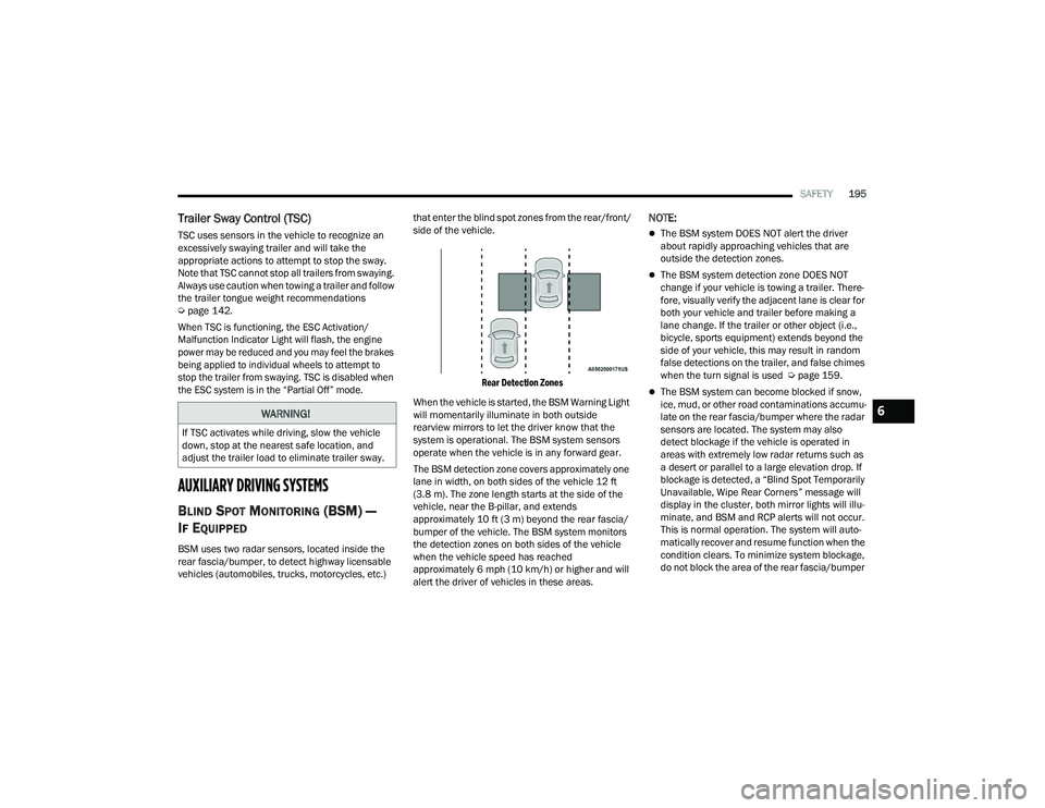
Rear Detection Zones
When the vehicle is started, the BSM Warning Light
will momentarily illuminate in both outside
rearview mirrors to let the driver know that the
system is operational. The BSM system sensors
operate when the vehicle is in any forward gear.
The BSM detection zone covers approximately one
lane in width, on both sides of the vehicle 12 ft
(3.8 m). The zone length starts at the side of the
vehicle, near the B-pillar, and extends
approximately 10 ft (3 m) beyond the rear fascia/
bumper of the vehicle. The BSM system monitors
the detection zones on both sides of the vehicle
when the vehicle speed has reached
approximately 6 mph (10 km/h) or higher and will
alert the driver of vehicles in these areas.
NOTE:
The BSM system DOES NOT alert the driver
about rapidly approaching vehicles that are
outside the detection zones.
The BSM system detection zone DOES NOT
change if your vehicle is towing a trailer. There -
fore, visually verify the adjacent lane is clear for
both your vehicle and trailer before making a
lane change. If the trailer or other object (i.e.,
bicycle, sports equipment) extends beyond the
side of your vehicle, this may result in random
false detections on the trailer, and false chimes
when the turn signal is used Ú page 159.
The BSM system can become blocked if snow,
ice, mud, or other road contaminations accumu -
late on the rear fascia/bumper where the radar
sensors are located. The system may also
detect blockage if the vehicle is operated in
areas with extremely low radar returns such as
a desert or parallel to a large elevation drop. If
blockage is detected, a “Blind Spot Temporarily
Unavailable, Wipe Rear Corners” message will
display in the cluster, both mirror lights will illu -
minate, and BSM and RCP alerts will not occur.
This is normal operation. The system will auto -
matically recover and resume function when the
condition clears. To minimize system blockage,
do not block the area of the rear fascia/bumper
WARNING!
If TSC activates while driving, slow the vehicle
down, stop at the nearest safe location, and
adjust the trailer load to eliminate trailer sway.
6
21_WD_OM_EN_USC_t.book Page 195
Page 201 of 340
SAFETY199
NOTE:Whenever an audible alert is requested by the
BSM system, the radio is also muted.
When the system is in RCP, the system shall
respond with both visual and audible alerts when a
detected object is present. Whenever an audible
alert is requested, the radio is also muted. Turn/
hazard signal status is ignored; the RCP state
always requests the chime.
Blind Spot Alert Off
When the BSM system is turned off there will be no
visual or audible alerts from either the BSM or RCP
systems.
NOTE:The BSM system will store the current operating
mode when the vehicle is shut off. Each time the
vehicle is started the previously stored mode will
be recalled and used.
FORWARD COLLISION WARNING (FCW)
W
ITH MITIGATION
FCW with Mitigation provides the driver with
audible warnings, visual warnings (within the
instrument cluster display), and may apply a brake
jerk to warn the driver when it detects a potential
frontal collision. The warnings and limited braking
are intended to provide the driver with enough time
to react, avoid or mitigate the potential collision.
NOTE:FCW monitors the information from the forward
looking sensors as well as the Electronic Brake
Controller (EBC) to calculate the probability of a
forward collision. When the system determines
that a forward collision is probable, the driver will
be provided with audible and visual warnings and
may provide a brake jerk warning. If the driver does
not take action based upon these progressive
warnings, then the system will provide a limited
level of active braking to help slow the vehicle and
mitigate the potential forward collision. If the driver
reacts to the warnings by braking and the system
determines that the driver intends to avoid the
collision by braking but has not applied sufficient
brake force, the system will compensate and
provide additional brake force as required.
If an FCW with Mitigation event begins at a speed
below 38 mph (62 km/h), the system may provide
the maximum or partial braking to mitigate the
potential forward collision. If the Forward Collision
Warning with Mitigation event stops the vehicle
completely, the system will hold the vehicle at a
standstill for two seconds and then release the
brakes.
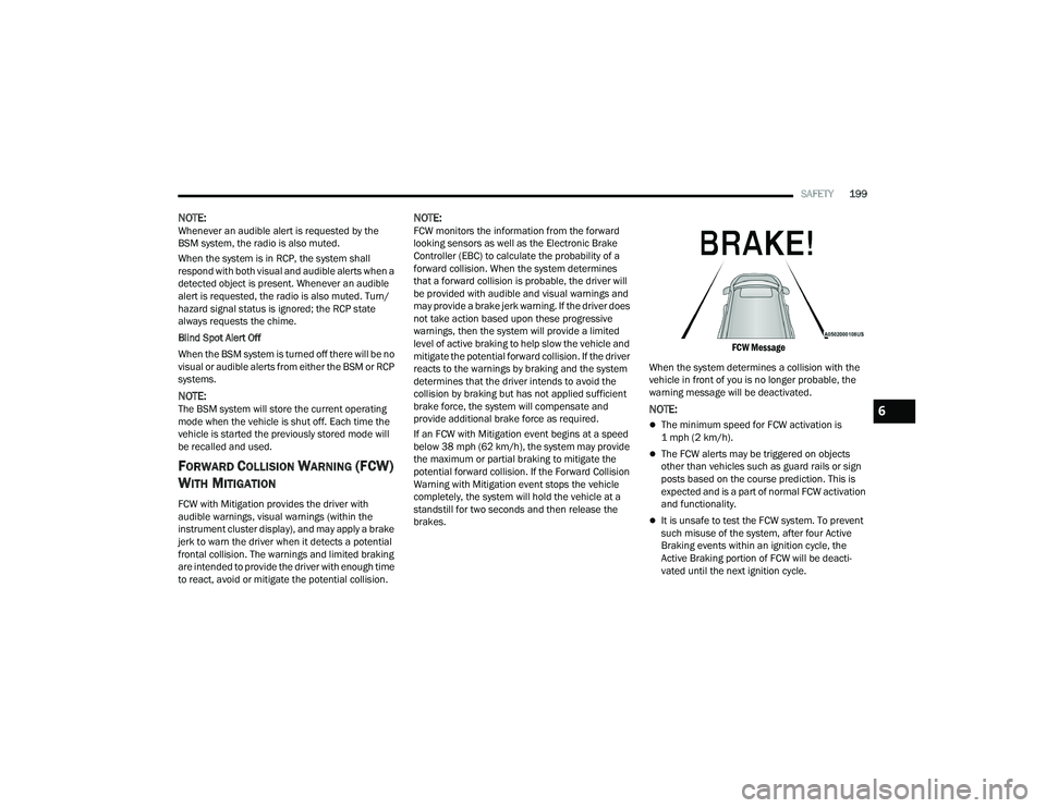
FCW Message
When the system determines a collision with the
vehicle in front of you is no longer probable, the
warning message will be deactivated.
NOTE:
The minimum speed for FCW activation is
1 mph (2 km/h).
The FCW alerts may be triggered on objects
other than vehicles such as guard rails or sign
posts based on the course prediction. This is
expected and is a part of normal FCW activation
and functionality.
It is unsafe to test the FCW system. To prevent
such misuse of the system, after four Active
Braking events within an ignition cycle, the
Active Braking portion of FCW will be deacti -
vated until the next ignition cycle.
6
21_WD_OM_EN_USC_t.book Page 199
Page 335 of 340
333
Warning Instrument Cluster Descriptions
.... 93Load Shed Battery Saver Mode....................... 89Load Shed Battery Saver On............................ 89Load Shed Electrical Load Reduction.............. 89Load Shed Intelligent Battery Sensor.............. 89Loading Vehicle............................................. 141Tires.......................................................... 300Locks Child Protection........................................... 26Manual........................................................ 22Power Door.................................................. 23Lubrication, Body........................................... 276Lug Nuts/Bolts.............................................. 317Luggage Carrier............................................... 77
M
Maintenance................................................... 74Maintenance Free Battery............................. 270Maintenance Schedule.................................. 264Malfunction Indicator Light
(Check Engine)....................................... 94, 100ManualService...................................................... 327Memory Feature (Memory Seats).................... 28Memory Seat................................................... 28Memory Seats And Radio................................ 28Methanol....................................................... 319Mirrors............................................................. 42Electric Remote........................................... 44Exterior Folding........................................... 44
Heated......................................................... 44Outside........................................................ 43Rearview......................................42, 43, 243Vanity.......................................................... 43Modifications/AlterationsVehicle......................................................... 10Monitor, Tire Pressure System...................... 201Mopar Parts.................................................. 326Multi-Function Control Lever............................ 48
N
New Vehicle Break-In Period......................... 104
O
Occupant Restraints..................................... 204Octane Rating, Gasoline (Fuel)..................... 318Oil Change Indicator........................................ 85Reset........................................................... 85Oil Filter, Change.......................................... 272Oil Filter, Selection........................................ 272Oil Pressure Light............................................. 93Oil, Engine..................................................... 271Capacity.................................................... 321Checking................................................... 270Dipstick.................................................... 270Disposal................................................... 272Filter......................................................... 272Filter Disposal........................................... 272Identification Logo.................................... 272Materials Added To.................................. 272
Pressure Warning Light................................93Recommendation............................ 271, 321Synthetic................................................... 272Viscosity.................................................... 321Onboard Diagnostic System.............................99Operating Precautions.....................................99Operator ManualOwner's Manual........................................ 327Outside Rearview Mirrors.................................43Overheating, Engine...................................... 258
P
Paint Care..................................................... 313Parking Brake............................................... 105ParkSense System, Rear............................... 130Passive Entry....................................................23Pets............................................................... 239Pinch Protection...............................................74Placard, Tire And Loading Information.......... 300PowerBrakes...................................................... 317Distribution Center (Fuses)....................... 287Door Locks...................................................23Inverter........................................................70Liftgate........................................................75Mirrors.........................................................44Outlet (Auxiliary Electrical Outlet).................68Seats...........................................................35Steering........................................... 117, 323Sunroof........................................................73
11
21_WD_OM_EN_USC_t.book Page 333