clock DODGE DURANGO 2021 Owners Manual
[x] Cancel search | Manufacturer: DODGE, Model Year: 2021, Model line: DURANGO, Model: DODGE DURANGO 2021Pages: 340, PDF Size: 20.38 MB
Page 51 of 340

GETTING TO KNOW YOUR VEHICLE49
Headlight Switch (Vehicles Sold In Canada)
NOTE:Vehicles sold in Canada are equipped with a head -
light switch without the OFF position. In order to
turn the exterior lights off, the headlight switch
must be rotated to AUTO position.
To turn on the headlights, rotate the headlight
switch clockwise. When the headlight switch is on,
the parking lights, taillights, license plate light and
instrument panel lights are also turned on. To turn
off the headlights, rotate the headlight switch back
to the O (off) position.
NOTE:For vehicles sold in Canada, rotate the headlight
switch clockwise from the parking lights and
instrument panel lights position to the first detent
to turn on headlights, parking lights, and
instrument panel lights. Rotate the headlight
switch to the second detent for the AUTO position.
NOTE:
Your vehicle is equipped with plastic headlight
and fog light (if equipped) lenses that are lighter
and less susceptible to stone breakage than
glass lights. Plastic is not as scratch resistant as
glass and therefore different lens cleaning
procedures must be followed.
To minimize the possibility of scratching the
lenses and reducing light output, avoid wiping
with a dry cloth. To remove road dirt, wash with
a mild soap solution followed by rinsing.
DAYTIME RUNNING LIGHTS (DRLS)
The Daytime Running Lights (DRLs) come on
whenever the engine is running. The lights will
remain on until the ignition is placed in the OFF
position, or the parking brake is engaged. The
headlight switch must be used during normal
nighttime driving.
NOTE:
For vehicles sold in Canada, the Daytime
Running Lights will automatically deactivate
when the front fog lights are turned on.
If allowed by law in the country in which the
vehicle was purchased, the Daytime Running
Lights can be turned on and off using the Ucon -
nect system Ú page 159.
On some vehicles, the Daytime Running Lights
may deactivate or reduce intensity on one side
of the vehicle (when a turn signal is activated on
that side), or on both sides of the vehicle (when
the hazard warning lights are activated).
HIGH/LOW BEAM SWITCH
Push the multifunction lever toward the instrument
panel to switch the headlights to high beams.
Pulling the multifunction back will turn the low
beams on.
1 — Rotate Headlight Switch
2 — Dimmer Control
3 — Fog Light Switch
CAUTION!
Do not use abrasive cleaning components,
solvents, steel wool or other abrasive materials
to clean the lenses.
2
21_WD_OM_EN_USC_t.book Page 49
Page 52 of 340
50GETTING TO KNOW YOUR VEHICLE
AUTOMATIC HIGH BEAM — IF EQUIPPED
The Automatic High Beam Headlamp Control
system provides increased forward lighting at night
by automatically controlling the high beams
through the use of a camera mounted on the
inside rearview mirror. This camera detects vehicle
specific light and automatically switches from high
beams to low beams until the approaching vehicle
is out of view.
NOTE:
The Automatic High Beam Headlamp Control
can be turned on or off by selecting or dese -
lecting “Auto Dim High Beams” within your
Uconnect Settings Ú page 159, as well as
turning the headlight switch to the AUTO posi -
tion.
Broken, muddy, or obstructed headlights and
taillights of vehicles in the field of view will
cause headlights to remain on longer (closer to
the vehicle). Also, dirt, film, and other obstruc -
tions on the windshield or camera lens will
cause the system to function improperly.
If the windshield or Automatic High Beam Head -
lamp Control mirror is replaced, the mirror must
be re-aimed to ensure proper performance. See
a local authorized dealer.
FLASH-TO-PASS
You can signal another vehicle with your headlights
by lightly pulling the multifunction lever toward you.
This will cause the high beam headlights to turn on,
and remain on, until the lever is released.
AUTOMATIC HEADLIGHTS
This system automatically turns the headlights on
or off according to ambient light levels. To turn the
system on, rotate the headlight switch
counterclockwise to the AUTO position. When the
system is on, the headlight time delay feature is
also on. This means the headlights will stay on for
up to 90 seconds after you place the ignition into
the OFF position. The headlight time delay can be
programmed 0/30/60/90 seconds within
Uconnect Settings Ú page 159.
To turn the automatic system off, move the
headlight switch out of the AUTO position.
NOTE:The engine must be running before the headlights
will come on in the automatic mode.
PARKING LIGHTS AND PANEL LIGHTS
To turn on the parking lights and instrument panel
lights, rotate the headlight switch clockwise. To
turn off the parking lights, rotate the headlight
switch back to the O (off) position.
AUTOMATIC HEADLIGHTS WITH WIPERS
If your vehicle is equipped with Automatic
Headlights, it also has this customer-
programmable feature. When your headlights are
in the automatic mode and the engine is running,
they will automatically turn on when the wiper
system is on. This feature is programmable
through the Uconnect system Ú page 159.
NOTE:When your headlights come on during the daytime,
the vehicle will monitor outside brightness and
decide if the instrument panel needs to be dimmed
or not.
21_WD_OM_EN_USC_t.book Page 50
Page 60 of 340
58GETTING TO KNOW YOUR VEHICLE
Faceplate: The blower speed increases as you
turn the blower control knob clockwise from the
lowest blower setting. The blower speed
decreases as you turn the blower control knob
counterclockwise.
Touchscreen: Use the small blower icon to
reduce the blower setting and the large blower
icon to increase the blower setting. Blower
speed can also be selected by pressing the
blower bar area between the icons.
Mode Control
Select Mode by pressing the Mode
button on the faceplate, or one of the
Mode buttons on the touchscreen to
change the airflow distribution mode.
The airflow distribution mode can be adjusted so
air comes from the instrument panel outlets, floor
outlets, defrost outlets and demist outlets.
Panel Mode
Air comes from the outlets in the
instrument panel. Each of these outlets
can be individually adjusted to direct the
flow of air. The air vanes of the center
outlets and outboard outlets can be moved up and
down or side to side to regulate airflow direction.
There is a shut-off wheel located below the air
vanes to shut off or adjust the amount of airflow
from these outlets.
Bi-Level Mode
Air comes from the instrument panel
outlets and floor outlets. A slight amount
of air is directed through the defrost and
side window demister outlets.
NOTE:Bi-Level mode is designed under comfort condi -
tions to provide cooler air out of the panel outlets
and warmer air from the floor outlets.
Floor Mode
Air comes from the floor outlets. A slight
amount of air is directed through the
defrost and side window demister
outlets.
Mix Mode
Air is directed through the floor, defrost,
and side window demister outlets. This
setting works best in cold or snowy
conditions that require extra heat to the
windshield. This setting is good for maintaining
comfort while reducing moisture on the
windshield.
Climate Control OFF Button
Press and release this button to turn the
Climate Control ON/OFF.
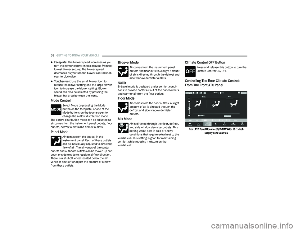
Controlling The Rear Climate Controls
From The Front ATC Panel
Front ATC Panel Uconnect 5/5 NAV With 10.1–inch
Display Rear Controls
21_WD_OM_EN_USC_t.book Page 58
Page 62 of 340
60GETTING TO KNOW YOUR VEHICLE
REAR MODE CONTROL
Select Mode by pressing one of the Mode
buttons on the touchscreen to change
the airflow distribution mode. The rear
airflow distribution mode can be
adjusted so air comes from the headliner outlets,
the floor outlets or both.
HEADLINER MODE
Air comes from the outlets in the
headliner. Each of these outlets can be
individually adjusted to direct the flow of
air. Moving the air vanes of the outlets to
one side shuts off the airflow.
BI-LEVEL MODE
Press this button on the touchscreen to
change the air distribution mode to
Bi-Level Mode. In Bi-Level Mode, air
comes from both the headliner outlets
and the floor outlets.
NOTE:In many temperature positions, the Bi-Level mode
is designed to provide cooler air out of the head -
liner outlets and warmer air from the floor outlets.
FLOOR MODE
Press this button on the touchscreen to
change the air distribution mode to Floor
Mode. In Floor Mode, air comes from the
floor outlets.
REAR CLIMATE CONTROL OFF BUTTON
To manually set the rear blower controls
to off, press the Rear Climate Control/
Blower Off button.
Rear Automatic Temperature Control
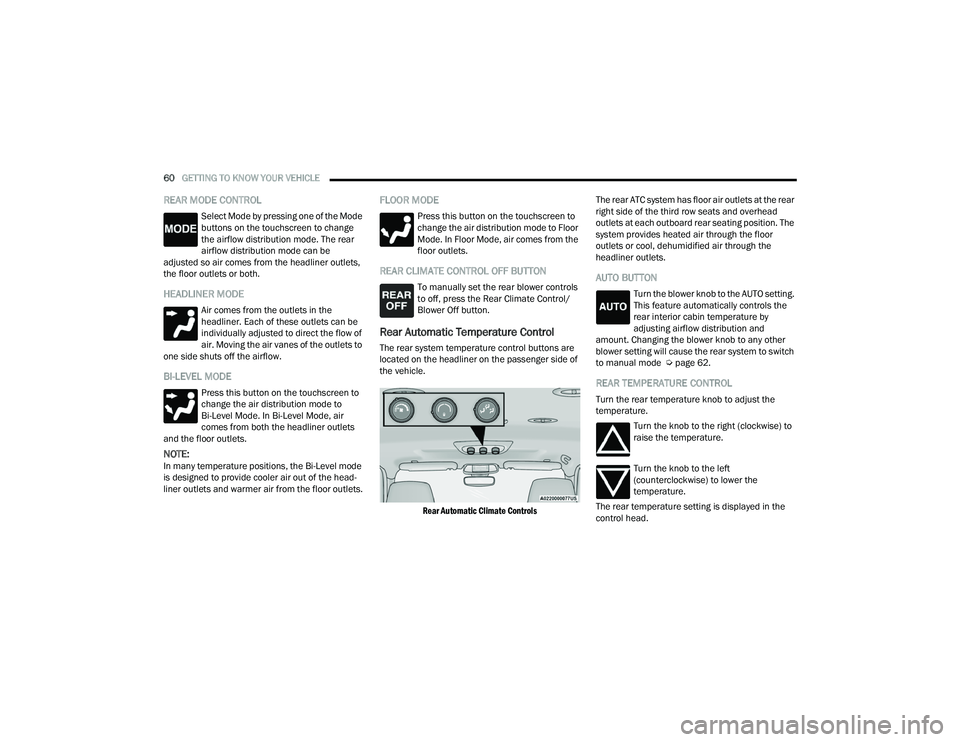
The rear system temperature control buttons are
located on the headliner on the passenger side of
the vehicle.
Rear Automatic Climate Controls
The rear ATC system has floor air outlets at the rear
right side of the third row seats and overhead
outlets at each outboard rear seating position. The
system provides heated air through the floor
outlets or cool, dehumidified air through the
headliner outlets.
AUTO BUTTON
Turn the blower knob to the AUTO setting.
This feature automatically controls the
rear interior cabin temperature by
adjusting airflow distribution and
amount. Changing the blower knob to any other
blower setting will cause the rear system to switch
to manual mode Ú page 62.
REAR TEMPERATURE CONTROL
Turn the rear temperature knob to adjust the
temperature.
Turn the knob to the right (clockwise) to
raise the temperature.
Turn the knob to the left
(counterclockwise) to lower the
temperature.
The rear temperature setting is displayed in the
control head.
21_WD_OM_EN_USC_t.book Page 60
Page 63 of 340
GETTING TO KNOW YOUR VEHICLE61
REAR BLOWER CONTROL
Turn the rear blower knob to regulate the
amount of air forced through the system
in any mode you select. The blower speed
increases as you move the knob
clockwise from the off position. The rear blower
setting is displayed in the control head.
REAR MODE CONTROL
Turn the rear mode knob to adjust airflow
distribution. The rear mode settings are
displayed in the control head. The rear
airflow distribution mode can be
adjusted so air comes from the headliner outlets,
the floor outlets, or both.
HEADLINER MODE
Air comes from the outlets in the
headliner. Each of these outlets can be
individually adjusted to direct the flow of
air. Moving the air vanes of the outlets to
one side will shut off the airflow.
BI-LEVEL MODE
Air comes from both the headliner outlets
and the floor outlets.
NOTE:In many temperature positions, the Bi-Level mode
is designed to provide cooler air out of the head -
liner outlets and warmer air from the floor outlets.
FLOOR MODE
Air comes from the floor outlets.
REAR TEMPERATURE LOCK
The Rear Temperature Lock symbol on
the control head is illuminated when the
rear controls are locked by the front
system.
Rear Lock
Pressing the Rear Temperature Lock button on the
Uconnect touchscreen, illuminates a lock symbol
in the rear display. The rear temperature and air
source are controlled from the front Uconnect
system.
Rear second row occupants can only adjust the
rear ATC control when the Rear Temperature Lock
button is turned off. The rear ATC is located in the headliner, near the
center of the vehicle.
Press the Rear Temperature Lock button on the
Uconnect touchscreen. This turns off the Rear
Temperature Lock icon in the rear temperature
knob.
Rotate the Rear Blower, Rear Temperature and
the Rear Mode Control knobs to suit your
comfort needs.
ATC is selected by adjusting the rear blower
knob counterclockwise to AUTO.
Once the desired temperature is displayed, the
ATC System will automatically achieve and
maintain that comfort level. When the system is
set up for your comfort level, it is not necessary to
change the settings. You will experience the
greatest efficiency by simply allowing the system to
function automatically.
2
21_WD_OM_EN_USC_t.book Page 61
Page 148 of 340

146STARTING AND OPERATING
NOTE:The trailer tongue weight must be considered as
part of the combined weight of occupants and
cargo, and should never exceed the weight refer -
enced on the Tire and Loading Information placard
Ú page 295. The addition of passengers and cargo
may require reducing trailer tongue load and Gross
Trailer Weight (GTW).
TRAILER HITCH RECEIVER COVER
R
EMOVAL — IF EQUIPPED
Your vehicle may be equipped with a trailer hitch
receiver cover, this must be removed to access the
trailer hitch receiver (if equipped). This cover is
located at the bottom center of the rear fascia/
bumper.
1. Turn the two locking retainers located at the
bottom of the hitch receiver cover a quarter
turn counterclockwise and pull bottom of the
hitch receiver cover outward (towards you).
Hitch Receiver Cover
2. Pull the bottom of the cover outward (towards you) then downwards to disengage the tabs
located at the top of the hitch receiver cover to
remove.
Hitch Receiver Cover
To reinstall the cover after towing, repeat the
procedure in reverse order.
NOTE:Be sure to engage all tabs of the hitch receiver
cover in the bumper fascia prior to installation.
1 — Hitch Receiver Cover
2 — Locking Retainers
21_WD_OM_EN_USC_t.book Page 146
Page 167 of 340
MULTIMEDIA165
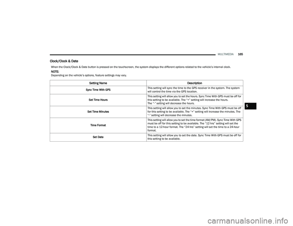
Clock/Clock & Date
When the Clock/Clock & Date button is pressed on the touchscreen, the system displays the different options related to the vehicle’s internal clock.
NOTE:Depending on the vehicle’s options, feature settings may vary.
Setting Name Description
Sync Time With GPSThis setting will sync the time to the GPS receiver in the system. The system
will control the time via the GPS location.
Set Time Hours This setting will allow you to set the hours. Sync Time With GPS must be off for
this setting to be available. The “+” setting will increase the hours.
The “-” setting will decrease the hours.
Set Time Minutes This setting will allow you to set the minutes. Sync Time With GPS must be off
for this setting to be available. The “+” setting will increase the minutes. The
“-” setting will decrease the minutes.
Time Format This setting will allow you to set the time format (AM/PM). Sync Time With GPS
must be off for this setting to be available. The “12 hrs” setting will set the
time to a 12-hour format. The “24 hrs” setting will set the time to a 24-hour
format.
Set Date This setting will allow you to set the date. Sync Time With GPS must be off for
this setting to be available.
5
21_WD_OM_EN_USC_t.book Page 165
Page 251 of 340
IN CASE OF EMERGENCY249
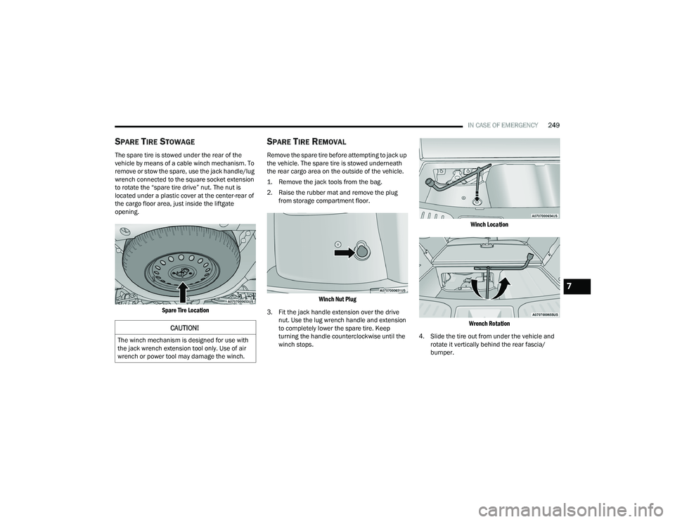
SPARE TIRE STOWAGE
The spare tire is stowed under the rear of the
vehicle by means of a cable winch mechanism. To
remove or stow the spare, use the jack handle/lug
wrench connected to the square socket extension
to rotate the “spare tire drive” nut. The nut is
located under a plastic cover at the center-rear of
the cargo floor area, just inside the liftgate
opening.
Spare Tire Location
SPARE TIRE REMOVAL
Remove the spare tire before attempting to jack up
the vehicle. The spare tire is stowed underneath
the rear cargo area on the outside of the vehicle.
1. Remove the jack tools from the bag.
2. Raise the rubber mat and remove the plug from storage compartment floor.
Winch Nut Plug
3. Fit the jack handle extension over the drive nut. Use the lug wrench handle and extension
to completely lower the spare tire. Keep
turning the handle counterclockwise until the
winch stops.
Winch Location
Wrench Rotation
4. Slide the tire out from under the vehicle and rotate it vertically behind the rear fascia/
bumper.
CAUTION!
The winch mechanism is designed for use with
the jack wrench extension tool only. Use of air
wrench or power tool may damage the winch.
7
21_WD_OM_EN_USC_t.book Page 249
Page 254 of 340
252IN CASE OF EMERGENCY
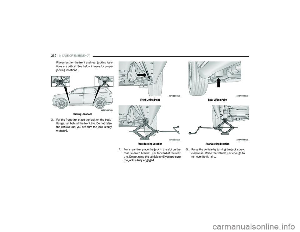
Placement for the front and rear jacking loca -
tions are critical. See below images for proper
jacking locations.
Jacking Locations
3. For the front tire, place the jack on the body flange just behind the front tire. Do not raise
the vehicle until you are sure the jack is fully
engaged.
Front Lifting Point
Front Jacking Location
4. For a rear tire, place the jack in the slot on the rear tie-down bracket, just forward of the rear
tire. Do not raise the vehicle until you are sure
the jack is fully engaged.
Rear Lifting Point
Rear Jacking Location
5. Raise the vehicle by turning the jack screw clockwise. Raise the vehicle just enough to
remove the flat tire.
21_WD_OM_EN_USC_t.book Page 252
Page 255 of 340
IN CASE OF EMERGENCY253
6. Remove the lug nuts and wheel.
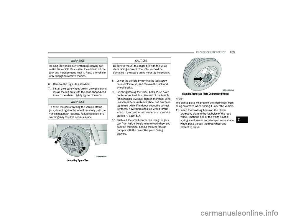
7. Install the spare wheel/tire on the vehicle and install the lug nuts with the cone-shaped end
toward the wheel. Lightly tighten the nuts.
Mounting Spare Tire
8. Lower the vehicle by turning the jack screw
counterclockwise, and remove the jack and
wheel blocks.
9. Finish tightening the wheel bolts. Push down on the wrench while at the end of the handle
for increased leverage. Tighten the wheel bolts
in a star pattern until each wheel bolt has been
tightened twice. If in doubt about the correct
tightness, have them checked with a torque
wrench by an authorized dealer or at a service
station Ú page 317.
10. Push out the small center cap using the jack tool from inside the aluminum road wheel and
position the wheel behind the rear fascia/
bumper with the protective plate facing
outward.
Installing Protective Plate On Damaged Wheel
NOTE:The plastic plate will prevent the road wheel from
being scratched when sliding it under the vehicle.
11. Insert the two long tubes on the plastic
protective plate in the lug holes of the road
wheel. Push the end of the winch’s cable,
spring, steel sleeve and stamped cone shape
wheel plate though the road wheel and
protective plate.
WARNING!
Raising the vehicle higher than necessary can
make the vehicle less stable. It could slip off the
jack and hurt someone near it. Raise the vehicle
only enough to remove the tire.
WARNING!
To avoid the risk of forcing the vehicle off the
jack, do not tighten the wheel nuts fully until the
vehicle has been lowered. Failure to follow this
warning may result in serious injury.
CAUTION!
Be sure to mount the spare tire with the valve
stem facing outward. The vehicle could be
damaged if the spare tire is mounted incorrectly.
7
21_WD_OM_EN_USC_t.book Page 253