traction control DODGE DURANGO 2021 Owners Manual
[x] Cancel search | Manufacturer: DODGE, Model Year: 2021, Model line: DURANGO, Model: DODGE DURANGO 2021Pages: 340, PDF Size: 20.38 MB
Page 88 of 340
86GETTING TO KNOW YOUR INSTRUMENT PANEL
Vehicles Equipped With Keyless Enter ‘n Go —
Ignition
Use the steering wheel instrument cluster display
controls for the following procedure(s):
1. Without pressing the brake pedal, push the ENGINE START/STOP button and place the
ignition in the ON/RUN position (do not start
the engine).
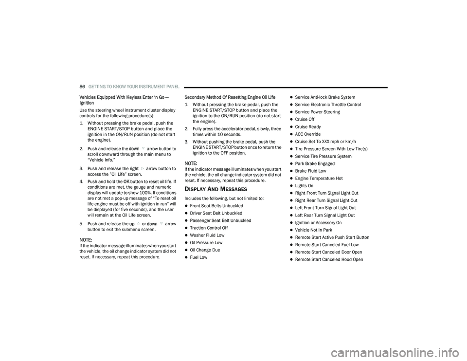
2. Push and release the down arrow button to
scroll downward through the main menu to
“Vehicle Info.”
3. Push and release the right arrow button to access the ”Oil Life” screen.
4. Push and hold the OK button to reset oil life. If
conditions are met, the gauge and numeric
display will update to show 100%. If conditions
are not met a pop-up message of “To reset oil
life engine must be off with ignition in run” will
be displayed (for five seconds), and the user
will remain at the Oil Life screen.
5. Push and release the up or down arrow
button to exit the submenu screen.
NOTE:If the indicator message illuminates when you start
the vehicle, the oil change indicator system did not
reset. If necessary, repeat this procedure. Secondary Method Of Resetting Engine Oil Life
1. Without pressing the brake pedal, push the
ENGINE START/STOP button and place the
ignition to the ON/RUN position (do not start
the engine).
2. Fully press the accelerator pedal, slowly, three times within 10 seconds.
3. Without pushing the brake pedal, push the ENGINE START/STOP button once to return the
ignition to the OFF position.
NOTE:If the indicator message illuminates when you start
the vehicle, the oil change indicator system did not
reset. If necessary, repeat this procedure.
DISPLAY AND MESSAGES
Includes the following, but not limited to:
Front Seat Belts Unbuckled
Driver Seat Belt Unbuckled
Passenger Seat Belt Unbuckled
Traction Control Off
Washer Fluid Low
Oil Pressure Low
Oil Change Due
Fuel Low
Service Anti-lock Brake System
Service Electronic Throttle Control
Service Power Steering
Cruise Off
Cruise Ready
ACC Override
Cruise Set To XXX mph or km/h
Tire Pressure Screen With Low Tire(s)
Service Tire Pressure System
Park Brake Engaged
Brake Fluid Low
Engine Temperature Hot
Lights On
Right Front Turn Signal Light Out
Right Rear Turn Signal Light Out
Left Front Turn Signal Light Out
Left Rear Turn Signal Light Out
Ignition or Accessory On
Vehicle Not In Park
Remote Start Active Push Start Button
Remote Start Canceled Fuel Low
Remote Start Canceled Door Open
Remote Start Canceled Hood Open
21_WD_OM_EN_USC_t.book Page 86
Page 114 of 340
112STARTING AND OPERATING
If a requested downshift would cause the
engine to over-speed, that shift will not occur.
The system will ignore attempts to upshift at too
low of a vehicle speed.
Holding the (-) paddle pressed, or holding the
gear selector in the (-) position, will downshift
the transmission to the lowest gear possible at
the current speed.
Transmission shifting will be more noticeable
when AutoStick is enabled.
The system may revert to automatic shift mode
if a fault or overheat condition is detected.
To disengage AutoStick mode, return the gear
selector to the DRIVE (D) position, or press and
hold the (+) shift paddle until "D" is indicated in the
instrument cluster. You can shift in or out of
AutoStick mode at any time without taking your
foot off the accelerator pedal.
SPORT MODE — IF EQUIPPED
Your vehicle is equipped with a SPORT Mode
feature. The engine, transmission, and steering
systems are all set to their SPORT settings. SPORT
Mode will provide improved throttle response and
modified transmission shift points for an enhanced
driving experience, as well as greater amount of
steering feel. This mode may be activated and
deactivated by pushing the SPORT button on the
instrument panel switch bank.
ALL-WHEEL DRIVE OPERATION
SINGLE-SPEED OPERATING
I
NSTRUCTIONS/PRECAUTIONS —
I
F EQUIPPED
This system contains a single-speed (HI range only)
transfer case, which provides convenient full-time
All-Wheel Drive (AWD). No driver interaction is
required. The Brake Traction Control (BTC) System,
which combines standard ABS and Traction
Control, provides resistance to any wheel that is
slipping to allow additional torque transfer to
wheels with traction.
NOTE:This system is not appropriate for conditions where
AWD Low is recommended Ú page 157.
ELECTRONICALLY SHIFTED TRANSFER
C
ASE — IF EQUIPPED
This is an electronically shifted transfer case and it
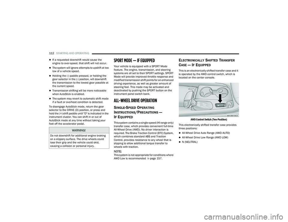
is operated by the AWD control switch, which is
located on the center console.
AWD Control Switch (Two-Position)
This electronically shifted transfer case provides
three positions:
All-Wheel Drive Auto Range (AWD AUTO)
All-Wheel Drive Low Range (AWD LOW)
N (NEUTRAL)
WARNING!
Do not downshift for additional engine braking
on a slippery surface. The drive wheels could
lose their grip and the vehicle could skid,
causing a collision or personal injury.
21_WD_OM_EN_USC_t.book Page 112
Page 117 of 340
STARTING AND OPERATING115
TOW N GO — IF EQUIPPED
Tow N Go combines the capabilities of the vehicle
control systems, along with driver input, to provide
optimum performance for road conditions.
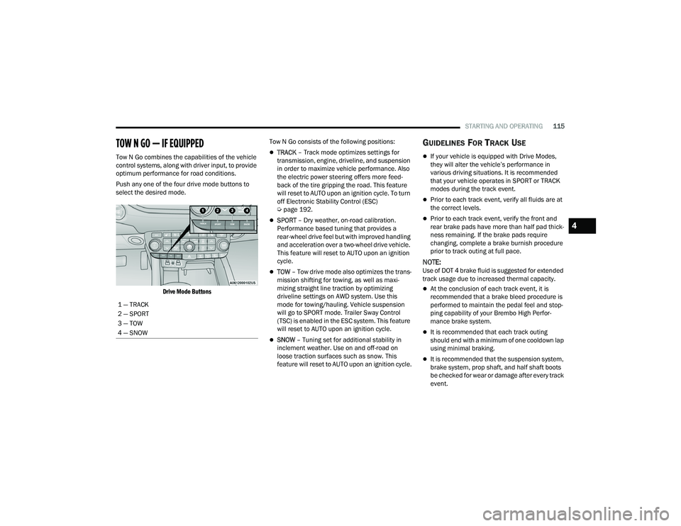
Push any one of the four drive mode buttons to
select the desired mode.
Drive Mode Buttons
Tow N Go consists of the following positions:TRACK
– Track mode optimizes settings for
transmission, engine, driveline, and suspension
in order to maximize vehicle performance. Also
the electric power steering offers more feed -
back of the tire gripping the road. This feature
will reset to AUTO upon an ignition cycle. To turn
off Electronic Stability Control (ESC)
Ú page 192.
SPORT – Dry weather, on-road calibration.
Performance based tuning that provides a
rear-wheel drive feel but with improved handling
and acceleration over a two-wheel drive vehicle.
This feature will reset to AUTO upon an ignition
cycle.
TOW – Tow drive mode also optimizes the trans -
mission shifting for towing, as well as maxi -
mizing straight line traction by optimizing
driveline settings on AWD system. Use this
mode for towing/hauling. Vehicle suspension
will go to SPORT mode. Trailer Sway Control
(TSC) is enabled in the ESC system. This feature
will reset to AUTO upon an ignition cycle.
SNOW – Tuning set for additional stability in
inclement weather. Use on and off-road on
loose traction surfaces such as snow. This
feature will reset to AUTO upon an ignition cycle.
GUIDELINES FOR TRACK USE
If your vehicle is equipped with Drive Modes,
they will alter the vehicle’s performance in
various driving situations. It is recommended
that your vehicle operates in SPORT or TRACK
modes during the track event.
Prior to each track event, verify all fluids are at
the correct levels.
Prior to each track event, verify the front and
rear brake pads have more than half pad thick -
ness remaining. If the brake pads require
changing, complete a brake burnish procedure
prior to track outing at full pace.
NOTE:Use of DOT 4 brake fluid is suggested for extended
track usage due to increased thermal capacity.
At the conclusion of each track event, it is
recommended that a brake bleed procedure is
performed to maintain the pedal feel and stop -
ping capability of your Brembo High Perfor -
mance brake system.
It is recommended that each track outing
should end with a minimum of one cooldown lap
using minimal braking.
It is recommended that the suspension system,
brake system, prop shaft, and half shaft boots
be checked for wear or damage after every track
event.
1 — TRACK
2 — SPORT
3 — TOW
4 — SNOW
4
21_WD_OM_EN_USC_t.book Page 115
Page 126 of 340
124STARTING AND OPERATING
NOTE:Fixed Speed Cruise Control cannot be set below
20 mph (32 km/h).
If either system is set when the vehicle speed is
above 20 mph (32 km/h), the set speed shall be
the current speed of the vehicle.
NOTE:
Keeping your foot on the accelerator pedal can
cause the vehicle to continue to accelerate
beyond the set speed. If this occurs, the
message “DRIVER OVERRIDE” will display in the
instrument cluster display.
If you continue to accelerate beyond the set
speed while ACC is enabled, the system will not
be controlling the distance between your vehicle
and the vehicle ahead. The vehicle speed will
only be determined by the position of the accel-
erator pedal.
To Cancel
The following conditions cancel the ACC or Fixed
Speed Cruise Control systems:
The brake pedal is applied
The CANC (cancel) button is pushed
The Anti-Lock Brake System (ABS) activates
The gear selector is removed from the DRIVE
position
The Electronic Stability Control/Traction Control
System (ESC/TCS) activates
The vehicle parking brake is applied
The Trailer Sway Control (TSC) activates
The driver switches ESC to Full Off mode
The braking temperature exceeds normal range
(overheated)
The following conditions will only cancel the ACC
system:
Driver seat belt is unbuckled at low speeds
Driver door is opened at low speeds
To Turn Off
The system will turn off and erase the set speed in
memory if:
The Adaptive Cruise Control (ACC) on/off button
is pushed
The Fixed Speed Cruise Control on/off button is
pushed
The ignition is placed in the OFF position
4WD Low is engaged
To Resume
If there is a set speed in memory, push the RES
(resume) button and remove your foot from the
accelerator pedal. The instrument cluster display
will show the last set speed.
Resume can be used at any speed above 20 mph
(32 km/h) when only Fixed Speed Cruise Control is
being used.
Resume can be used at any speed above 0 mph
(0 km/h) when ACC is active.
NOTE:
While in ACC mode when the vehicle comes to a
complete stop longer than two seconds, the
system will cancel. The driver will have to apply
the brakes to keep the vehicle at a standstill.
ACC cannot be resumed if there is a stationary
vehicle in front of your vehicle in close proximity.
WARNING!
The Resume function should only be used if
traffic and road conditions permit. Resuming a
set speed that is too high or too low for
prevailing traffic and road conditions could
cause the vehicle to accelerate or decelerate too
sharply for safe operation. Failure to follow these
warnings can result in a collision and death or
serious personal injury.
21_WD_OM_EN_USC_t.book Page 124
Page 141 of 340
STARTING AND OPERATING139
CHANGING LANESENSE STATUS
The LaneSense system has settings to adjust the
intensity of the torque warning and the warning
zone sensitivity (early/late) that you can configure
through the Uconnect system Ú page 159.
NOTE:
When enabled the system operates above
37 mph (60 km/h) and below 112 mph
(180 km/h).
The warnings are disabled with use of the turn
signal.
The system will not apply torque to the steering
wheel whenever a safety system engages
(Anti-Lock Brakes, Traction Control System,
Electronic Stability Control, Forward Collision
Warning, etc.).
PARKVIEW REAR BACK UP CAMERA
Your vehicle is equipped with the ParkView Rear
Back Up Camera that allows you to see an
on-screen image of the rear surroundings of your
vehicle whenever the gear selector is put into
REVERSE. The image will be displayed on the
Navigation/Multimedia radio display screen along
with a caution note to “Check Entire Surroundings” across the top of the screen. After five seconds this
note will disappear. The ParkView camera is
located on the rear of the vehicle above the rear
license plate.
When the vehicle is shifted out of REVERSE (with
camera delay turned off), the rear camera mode is
exited and the previous screen appears.
Manual Activation Of The Backup Camera
1. Press the Vehicle Menu button located at the
bottom of the Uconnect display. Then select
the Control” tab.
2. Press the Rear View Camera button to turn the Rear View Camera system on.
NOTE:The ParkView Rear Back Up Camera has program -
mable modes of operation that may be selected
through the Uconnect system Ú page 159. In
certain radio configurations, these modes of oper -
ation will be found in the “Camera” section of the
vehicle settings menu.
When the vehicle is shifted out of REVERSE with
camera delay turned off, the rear camera mode is
exited and the previous screen appears. When the
vehicle is shifted out of REVERSE with camera
delay turned on, the camera image will continue to
be displayed for up to 10 seconds after shifting out of REVERSE unless the following conditions occur:
the vehicle speed exceeds 8 mph (13 km/h), the
vehicle is shifted into PARK, the vehicle’s ignition is
placed in the OFF position, or the touchscreen
button X to disable the display of the Rear View
Camera is pressed.
When enabled, active guidelines are overlaid on
the image to illustrate the width of the vehicle and
its projected backup path based on the steering
wheel position. A dashed center line overlay
indicates the center of the vehicle to assist with
parking or aligning to a hitch/receiver. Different
colored zones indicate the distance to the rear of
the vehicle.
The following table shows the approximate
distances for each zone:
Zone Distance To The Rear Of
The Vehicle
Red 0 - 1 ft
(0 - 30 cm)
Yellow 1 ft - 6.5 ft
(30 cm - 2 m)
Green 6.5 ft or greater
(2 m or greater)
4
21_WD_OM_EN_USC_t.book Page 139
Page 159 of 340
STARTING AND OPERATING157
OFF-ROAD DRIVING TIPS
When To Use 4WD Low — If Equipped
When off-road driving, shift to 4WD Low for
additional traction. This range should be limited to
extreme situations such as deep snow, mud, or
sand where additional low speed pulling power is
needed. Vehicle speeds in excess of 25 mph
(40 km/h) should be avoided when in 4WD Low.
Driving Through Water
Although your vehicle is capable of driving through
water, there are a number of precautions that
must be considered before entering the water. Driving through water more than a few inches/
centimeters deep will require extra caution to
ensure safety and prevent damage to your vehicle.
If you must drive through water, try to determine
the depth and the bottom condition (and location
of any obstacles) prior to entering. Proceed with
caution and maintain a steady controlled speed
less than 5 mph (8 km/h) in deep water to
minimize wave effects.
Flowing Water
If the water is swift flowing and rising (as in storm
run-off), avoid crossing until the water level
recedes and/or the flow rate is reduced. If you
must cross flowing water avoid depths in excess of
9 inches (23 cm). The flowing water can erode the
streambed, causing your vehicle to sink into
deeper water. Determine exit point(s) that are
downstream of your entry point to allow for drifting. Standing Water
Avoid driving in standing water deeper than
20 inches (51 cm), and reduce speed
appropriately to minimize wave effects. Maximum
speed in 20 inches (51 cm) of water is less than
5 mph (8 km/h).
Maintenance
After driving through deep water, inspect your
vehicle fluids and lubricants (engine oil,
transmission oil, axle, transfer case) to ensure the
fluids have not been contaminated. Contaminated
fluid (milky, foamy in appearance) should be
flushed/changed as soon as possible to prevent
component damage.
Driving In Snow, Mud And Sand
In heavy snow, when pulling a load, or for
additional control at slower speeds, shift the
transmission to a low gear and shift the transfer
case to AWD Low if necessary Ú
page 112. Only
shift into a lower gear to maintain forward motion.
Over-revving the engine can spin the wheels and
traction will be lost.
Avoid abrupt downshifts on icy or slippery roads,
because engine braking may cause skidding and
loss of control.
.
WARNING!
Do not drive in 4WD Low on dry pavement;
driveline damage may result. 4WD Low locks
front and rear drivelines together and does not
allow for differential action between the front to
rear driveshafts. Driving in 4WD Low on
pavement will cause driveline binding; use only
on wet or slippery surfaces.
CAUTION!
When driving through water, do not exceed
5 mph (8 km/h). Always check water depth
before entering as a precaution, and check all
fluids afterward. Driving through water may
cause damage not covered by the New Vehicle
Limited Warranty.
4
21_WD_OM_EN_USC_t.book Page 157
Page 191 of 340
189
(Continued)
SAFETY
SAFETY FEATURES
ANTI-LOCK BRAKE SYSTEM (ABS)
The ABS provides increased vehicle stability and
brake performance under most braking conditions.
The system automatically prevents wheel lock, and
enhances vehicle control during braking.
The ABS performs a self-check cycle to ensure that
the ABS is working properly each time the vehicle
is started and driven. During this self-check, you
may hear a slight clicking sound as well as some
related motor noises.
The ABS is activated during braking when the
system detects one or more wheels are beginning
to lock. Road conditions such as ice, snow, gravel,
bumps, railroad tracks, loose debris, or panic stops
may increase the likelihood of ABS activation(s).
You also may experience the following normal
characteristics when the ABS activates:
ABS motor noise or clicking sounds (you may
continue to hear for a short time after the stop).
Brake pedal pulsations.
A slight drop of the brake pedal at the end of
the stop.The ABS is designed to function with the Original
Equipment Manufacturer (OEM) tires. Modification
may result in degraded ABS performance.
Anti-Lock Brake System (ABS) Warning
Light
The yellow ABS Warning Light will turn on when the
ignition is placed in the ON/RUN mode and may
stay on for as long as four seconds.
If the ABS Warning Light remains on or comes on
while driving, it indicates that the anti-lock portion
of the brake system is not functioning and that
service is required. However, the conventional
brake system will continue to operate normally if
the ABS Warning Light is on.
WARNING!
The ABS contains sophisticated electronic
equipment that may be susceptible to interfer
-
ence caused by improperly installed or high
output radio transmitting equipment. This
interference can cause possible loss of
anti-lock braking capability. Installation of
such equipment should be performed by qual -
ified professionals.
Pumping of the Anti-Lock Brakes will diminish
their effectiveness and may lead to a collision.
Pumping makes the stopping distance longer.
Just press firmly on your brake pedal when you
need to slow down or stop.
The ABS cannot prevent the natural laws of
physics from acting on the vehicle, nor can it
increase braking or steering efficiency beyond
that afforded by the condition of the vehicle
brakes and tires or the traction afforded.
The ABS cannot prevent collisions, including
those resulting from excessive speed in turns,
following another vehicle too closely, or hydro -
planing.
The capabilities of an ABS equipped vehicle
must never be exploited in a reckless or
dangerous manner that could jeopardize the
user’s safety or the safety of others.
WARNING!
6
21_WD_OM_EN_USC_t.book Page 189
Page 192 of 340
190SAFETY
If the ABS Warning Light is on, the brake system
should be serviced as soon as possible to restore
the benefits of Anti-Lock Brakes. If the ABS
Warning Light does not come on when the ignition
is placed in the ON/RUN mode, have the light
repaired as soon as possible.
ELECTRONIC BRAKE CONTROL (EBC)
S
YSTEM
Your vehicle is equipped with an advanced
Electronic Brake Control (EBC) system. This system
includes Anti-Lock Brake System (ABS), Brake
Assist System (BAS), Electronic Brake Force
Distribution (EBD), Electronic Roll Mitigation
(ERM), Electronic Stability Control (ESC), Hill Start
Assist (HSA), and Traction Control System (TCS).
These systems work together to enhance both
vehicle stability and control in various driving
conditions.
Your vehicle may also be equipped with Dynamic
Steering Torque (DST), Rain Brake Support (RBS),
Ready Alert Braking (RAB), and Trailer Sway
Control (TSC).
Brake Assist System (BAS)
The BAS is designed to optimize the vehicle’s
braking capability during emergency braking
maneuvers. The system detects an emergency
braking situation by sensing the rate and amount
of brake application and then applies optimum pressure to the brakes. This can help reduce
braking distances. The BAS complements the
Anti-Lock Brake System (ABS). Applying the brakes
very quickly results in the best BAS assistance. To
receive the benefit of the system, you must apply
continuous braking pressure during the stopping
sequence (do not “pump” the brakes). Do not
reduce brake pedal pressure unless braking is no
longer desired. Once the brake pedal is released,
the BAS is deactivated.Brake System Warning Light
The red Brake System Warning Light will turn on
when the ignition is placed in the ON/RUN mode
and may stay on for as long as four seconds.
If the Brake System Warning Light remains on or
comes on while driving, it indicates that the brake
system is not functioning properly and that
immediate service is required. If the Brake System
Warning Light does not come on when the ignition
is placed in the ON/RUN mode, have the light
repaired as soon as possible.
Dynamic Steering Torque (DST)
DST is a feature of the ESC and Electric Power
Steering (EPS) modules that provides torque at the
steering wheel for certain driving conditions in
which the ESC module is detecting vehicle
instability. The torque that the steering wheel
receives is only meant to help the driver realize
optimal steering behavior in order to reach/
maintain vehicle stability. The only notification the
driver receives that the feature is active is the
torque applied to the steering wheel.
NOTE:The DST feature is only meant to help the driver
realize the correct course of action through small
torques on the steering wheel, which means the
effectiveness of the DST feature is highly
dependent on the driver’s sensitivity and overall
reaction to the applied torque. It is very important
to realize that this feature will not steer the vehicle,
meaning the driver is still responsible for steering
the vehicle.
WARNING!
The Brake Assist System (BAS) cannot prevent
the natural laws of physics from acting on the
vehicle, nor can it increase the traction afforded
by prevailing road conditions. BAS cannot
prevent collisions, including those resulting from
excessive speed in turns, driving on very slippery
surfaces, or hydroplaning. The capabilities of a
BAS-equipped vehicle must never be exploited in
a reckless or dangerous manner, which could
jeopardize the user's safety or the safety of
others.
21_WD_OM_EN_USC_t.book Page 190
Page 193 of 340
SAFETY191
Electronic Brake Force Distribution (EBD)
EBD manages the distribution of the braking
torque between the front and rear axles by limiting
braking pressure to the rear axle. This is done to
prevent overslip of the rear wheels to avoid vehicle
instability, and to prevent the rear axle from
entering ABS before the front axle.
Electronic Roll Mitigation (ERM)
ERM anticipates the potential for wheel lift by
monitoring the driver’s steering wheel input and
the speed of the vehicle. When Electronic Roll
Mitigation (ERM) determines that the rate of
change of the steering wheel angle and vehicle’s
speed are sufficient to potentially cause wheel lift,
it then applies the appropriate brake and may also
reduce engine power to lessen the chance that
wheel lift will occur. ERM can only reduce the
chance of wheel lift occurring during severe or
evasive driving maneuvers; it cannot prevent
wheel lift due to other factors, such as road
conditions, leaving the roadway, or striking objects
or other vehicles.
Electronic Stability Control (ESC)
ESC enhances directional control and stability of
the vehicle under various driving conditions. ESC
corrects for oversteering or understeering of the
vehicle by applying the brake of the appropriate
wheel(s) to counteract the above conditions.
Engine power may also be reduced to help the
vehicle maintain the desired path.
Oversteer — when the vehicle is turning more
than appropriate for the steering wheel position.
Understeer — when the vehicle is turning less
than appropriate for the steering wheel position. ESC uses sensors in the vehicle to determine the
vehicle path intended by the driver and compares
it to the actual path of the vehicle. When the actual
path does not match the intended path, ESC
applies the brake of the appropriate wheel to
assist in counteracting the oversteer or understeer
condition.
The ESC Activation/Malfunction Indicator Light
located in the instrument cluster will start to flash
as soon as the ESC system becomes active. The
ESC Activation/Malfunction Indicator Light also
flashes when the Traction Control System (TCS) is
active. If the ESC Activation/Malfunction Indicator
Light begins to flash during acceleration, ease up
on the accelerator and apply as little throttle as
possible. Be sure to adapt your speed and driving
to the prevailing road conditions.
WARNING!
Many factors, such as vehicle loading, road
conditions and driving conditions, influence the
chance that wheel lift or rollover may occur. ERM
cannot prevent all wheel lift or rollovers,
especially those that involve leaving the roadway
or striking objects or other vehicles. The
capabilities of an ERM-equipped vehicle must
never be exploited in a reckless or dangerous
manner which could jeopardize the user's safety
or the safety of others.
6
21_WD_OM_EN_USC_t.book Page 191
Page 194 of 340
192SAFETY
(Continued)
ESC Operating Modes
Depending upon model and mode of operation, the
ESC system may have multiple operating modes.
ESC On
This is the normal operating mode for the ESC.
Whenever the vehicle is started, the ESC system
will be in this mode. This mode should be used for
most driving conditions. Alternate ESC modes
should only be used for specific reasons as noted
in the following paragraphs. Partial Off
This mode may be useful if the vehicle becomes
stuck. This mode may modify TCS and ESC
thresholds for activation, which allows for more
wheel spin than normally allowed.
To enter the “Partial Off” mode, momentarily push
the ESC OFF button and the ESC OFF Indicator
Light will illuminate. To turn the ESC on again,
momentarily push the ESC OFF button and the
ESC OFF Indicator Light will turn off.
NOTE:For vehicles with multiple partial ESC modes, the
push and release of the button will toggle the
ESC modes. Multiple attempts may be required to
return to "ESC On" mode.
WARNING!
Electronic Stability Control (ESC) cannot
prevent the natural laws of physics from
acting on the vehicle, nor can it increase the
traction afforded by prevailing road condi
-
tions. ESC cannot prevent accidents, including
those resulting from excessive speed in turns,
driving on very slippery surfaces, or hydro -
planing. ESC also cannot prevent accidents
resulting from loss of vehicle control due to
inappropriate driver input for the conditions.
Only a safe, attentive, and skillful driver can
prevent accidents. The capabilities of an ESC
equipped vehicle must never be exploited in a
reckless or dangerous manner which could
jeopardize the user’s safety or the safety of
others.Vehicle modifications, or failure to properly
maintain your vehicle, may change the
handling characteristics of your vehicle, and
may negatively affect the performance of the
ESC system. Changes to the steering system,
suspension, braking system, tire type and size
or wheel size may adversely affect ESC perfor -
mance. Improperly inflated and unevenly worn
tires may also degrade ESC performance. Any
vehicle modification or poor vehicle mainte -
nance that reduces the effectiveness of the
ESC system can increase the risk of loss of
vehicle control, vehicle rollover, personal
injury and death.
WARNING!
WARNING!
When in “Partial Off” mode, the TCS function -
ality of ESC, except for the limited slip feature
described in the TCS section, has been
disabled and the ESC OFF Indicator Light will
be illuminated. When in “Partial Off” mode,
the engine power reduction feature of TCS is
disabled, and the enhanced vehicle stability
offered by the ESC system is reduced.
Trailer Sway Control (TSC) is disabled when
the ESC system is in the “Partial Off” mode.
21_WD_OM_EN_USC_t.book Page 192