jump start DODGE DURANGO 2022 Owners Manual
[x] Cancel search | Manufacturer: DODGE, Model Year: 2022, Model line: DURANGO, Model: DODGE DURANGO 2022Pages: 332, PDF Size: 19.82 MB
Page 8 of 332
6
OCCUPANT RESTRAINT SYSTEMS .................... 196 Occupant Restraint Systems Features ........ 196
Important Safety Precautions....................... 197
Seat Belt Systems ........................................ 197
Supplemental Restraint Systems (SRS) ...... 203
Child Restraints ........................................... 216
SAFETY TIPS ......................................................... 231
Transporting Passengers .............................. 231Transporting Pets ....................................... 232
Connected Vehicles....................................... 232
Safety Checks You Should Make
Inside The Vehicle ........................................ 232
Periodic Safety Checks You Should
Make Outside The Vehicle ............................ 233
Exhaust Gas ................................................... 234Carbon Monoxide Warnings ......................... 234
IN CASE OF EMERGENCY
HAZARD WARNING FLASHERS ......................... 235
SOS AND ASSIST MIRROR — IF EQUIPPED...... 235
JACKING AND TIRE CHANGING.......................... 239 Preparations For Jacking .............................. 239Jack Location ................................................. 240
Spare Tire Stowage ....................................... 240
Spare Tire Removal ....................................... 241
Jacking Instructions ...................................... 242 JUMP STARTING ................................................. 246
Preparations For Jump Start ........................ 246
Jump Starting Procedure .............................. 247
REFUELING IN EMERGENCY –
IF EQUIPPED ........................................................ 248
IF YOUR ENGINE OVERHEATS ........................... 249
MANUAL PARK RELEASE ................................... 250
FREEING A STUCK VEHICLE .............................. 252
TOWING A DISABLED VEHICLE ........................ 253
Rear Wheel Drive Models ............................. 254
All Wheel Drive Models ................................. 254
ENHANCED ACCIDENT RESPONSE SYSTEM
(EARS) .................................................................. 254
EVENT DATA RECORDER (EDR) ........................ 254
SERVICING AND MAINTENANCE
SCHEDULED SERVICING..................................... 255
Maintenance Plan ......................................... 256
ENGINE COMPARTMENT .................................... 259
3.6L Engine ................................................... 259
5.7L Engine ................................................... 260
Checking Oil Level ......................................... 261
Adding Washer Fluid .................................... 261
Maintenance-Free Battery ........................... 261Pressure Washing ......................................... 262 VEHICLE MAINTENANCE ..................................... 262
Engine Oil ...................................................... 262
Engine Oil Filter ............................................ 263
Engine Air Cleaner Filter ............................... 263
Air Conditioner Maintenance ....................... 264
Accessory Drive Belt Inspection ................... 267Body Lubrication .......................................... 267Windshield Wiper Blades ............................. 268Exhaust System ............................................ 271
Cooling System.............................................. 272
Brake System ............................................... 274Automatic Transmission ............................... 275
Front/Rear Axle Fluid ................................... 276
Transfer Case ............................................... 276Fuses.............................................................. 277
Bulb Replacement ...................................... 284
TIRES ..................................................................... 286
Tire Safety Information ................................. 286
Tires — General Information ......................... 293
Tire Types....................................................... 296Spare Tires — If Equipped ............................ 297
Wheel And Wheel Trim Care ........................ 299Snow Traction Devices ................................ 300Tire Rotation Recommendations ................ 302
22_WD_OM_EN_USC_t.book Page 6
Page 103 of 332
STARTING AND OPERATING101
If the vehicle is not in PARK and the driver turns off
the engine, the vehicle may AutoPark.
AutoPark will engage when all of these conditions
are met:
Vehicle is equipped with an 8-speed transmis -
sion
Vehicle is not in PARK
Vehicle speed is 1.2 mph (1.9 km/h) or less
Ignition switched from ON/RUN to ACC
NOTE:For Keyless Enter ‘n Go™ equipped vehicles, the
engine will turn off and the ignition switch will
change to the ACC position. After 60 seconds, the
ignition switches to OFF automatically, unless the
driver turns the ignition switch OFF.
If the vehicle is not in PARK and the driver exits the
vehicle with the engine running, the vehicle may
AutoPark.
AutoPark will engage when all of these conditions
are met:
Vehicle is equipped with an 8-speed transmis -
sion
Vehicle is not in PARK
Vehicle speed is 1.2 mph (1.9 km/h) or less
Driver’s seat belt is unbuckled
Driver’s door is ajar
Brake pedal is not pressed The message “
AutoPark Engaged Shift to P then
Shift to Gear ” will display in the instrument cluster.
NOTE:In some cases the ParkSense graphic will be
displayed in the instrument cluster. In these cases,
the gear selector must be returned to “P” to select
desired gear.
If the driver shifts into PARK while moving, the
vehicle may AutoPark.
AutoPark will engage ONLY when vehicle speed is
1.2 mph (1.9 km/h) or less.
The message “ Vehicle Speed is Too High to Shift
to P ” will be displayed in the instrument cluster if
vehicle speed is above 1.2 mph (1.9 km/h).
4WD LOW — If Equipped
AutoPark will be disabled when operating the
vehicle in 4WD LOW.
The message “ AutoPark Disabled ” will be
displayed in the instrument cluster. Additional customer warnings will be given when
both of these conditions are met:Vehicle is not in PARK
Driver’s door is ajar
The message “ AutoPark Not Engaged” will be
displayed in the instrument cluster. A warning
chime will continue until you shift the vehicle into
PARK or the driver’s door is closed.
ALWAYS DO A VISUAL CHECK
that your vehicle is in
PARK by looking for the "P" in the instrument
cluster display and on the gear selector. As an
added precaution, always apply the parking brake
when exiting the vehicle.
EXTENDED PARK STARTING
NOTE:Extended Park condition occurs when the vehicle
has not been started or driven for at least 30 days.
1. Install a battery charger or jumper cables to the battery to ensure a full battery charge
during the crank cycle.
2. Place the ignition in the START position and release it when the engine starts.
3. If the engine fails to start within 10 seconds, place the ignition in the OFF position, wait
10 to 15 seconds to allow the starter to cool,
then repeat the “Extended Park Starting”
procedure.
WARNING!
If vehicle speed is above 1.2 mph (1.9 km/h), the
transmission will default to NEUTRAL until the
vehicle speed drops below 1.2 mph (1.9 km/h).
A vehicle left in the NEUTRAL position can roll. As
an added precaution, always apply the parking
brake when exiting the vehicle.
4
22_WD_OM_EN_USC_t.book Page 101
Page 248 of 332
246IN CASE OF EMERGENCY
14. Lower the jack to the fully closed position. Return the tools to the proper positions in the
tool bag. Fold the flap on the tool bag under
the tools and roll the tools in the bag
underneath the others. Use the hook and loop
fasteners to secure the tool bag to the jack
with the lug wrench on the forward side of the
jack. Expand the jack on the bracket by turning
the thumb screw clockwise until it is tight to
prevent rattles.
15. Reinstall the plastic plug into the floor of the cargo area. Roll up and store the Jack, Tool Kit
and Tire Changing Instructions. Reinstall the
cover for the jack in the rear storage bin.
16. Have the aluminum road wheel and tire repaired as soon as possible and properly
secure the spare tire, jack and tool kit.
JUMP STARTING
If your vehicle has a discharged battery, it can be
jump started using a set of jumper cables and a
battery in another vehicle, or by using a portable
battery booster pack. Jump starting can be
dangerous if done improperly, so please follow the
procedures in this section carefully.
NOTE:When using a portable battery booster pack, follow
the manufacturer's operating instructions and
precautions.
PREPARATIONS FOR JUMP START
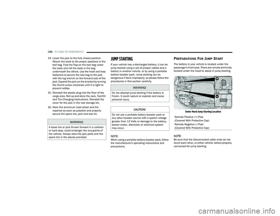
The battery in your vehicle is located under the
passenger's front seat. There are remote terminals
located under the hood to assist in jump starting.
Under Hood Jump Starting Location
NOTE:Be sure that the disconnected cable ends do not
touch each other, or either vehicle, before properly
connected for jump starting.
WARNING!
A loose tire or jack thrown forward in a collision
or hard stop, could endanger the occupants of
the vehicle. Always stow the jack parts and the
spare tire in the places provided.
WARNING!
Do not attempt jump starting if the battery is
frozen. It could rupture or explode and cause
personal injury.
CAUTION!
Do not use a portable battery booster pack or
any other booster source with a system voltage
greater than 12 Volts or damage to the battery,
starter motor, alternator or electrical system
may occur.Remote Positive (+) Post
(Covered With Protective Cap)
Remote Negative (-) Post
(Covered With Protective Cap)
22_WD_OM_EN_USC_t.book Page 246
Page 249 of 332
IN CASE OF EMERGENCY247
See the following steps to prepare for jump
starting:
1. Apply the parking brake, shift the automatic transmission into PARK (P) and turn the
ignition OFF.
2. Turn off the heater, radio, and all electrical accessories.
3. Remove the protective cover over the remote positive (+) battery post. Pull upward on the
cover to remove it.
4. Remove the protective cover over the remote negative (-) battery post.
5. If using another vehicle to jump start the battery, park the vehicle within the jumper
cable’s reach, apply the parking brake and
make sure the ignition is OFF.
JUMP STARTING PROCEDURE
NOTE:Make sure at all times that unused ends of jumper
cables are not contacting each other or either
vehicle while making connections.
Connecting The Jumper Cables
1. Connect the positive
(+) end of the jumper
cable to the remote positive (+)
post of the
discharged vehicle.
2. Connect the opposite end of the positive (+)
jumper cable to the positive (+) post of the
booster battery.
3. Connect the negative (-) end of the jumper
cable to the negative (-) post of the booster
battery.
4. Connect the opposite end of the negative (-)
jumper cable to the remote negative (-) post
(exposed metallic/unpainted post of the
discharge vehicle) located on the right hand
side next to the underhood fuse box.
WARNING!
Do not allow vehicles to touch each other as this
could establish a ground connection and
personal injury could result.
WARNING!
Take care to avoid the radiator cooling fan
whenever the hood is raised. It can start
anytime the ignition switch is ON. You can be
injured by moving fan blades.
Remove any metal jewelry such as rings,
watch bands and bracelets that could make
an inadvertent electrical contact. You could be
seriously injured.
Batteries contain sulfuric acid that can burn
your skin or eyes and generate hydrogen gas
which is flammable and explosive. Keep open
flames or sparks away from the battery.
WARNING!
Failure to follow this jump starting procedure
could result in personal injury or property
damage due to battery explosion.
CAUTION!
Failure to follow these procedures could result in
damage to the charging system of the booster
vehicle or the discharged vehicle.
WARNING!
Do not connect the jumper cable to the
negative (-) post of the discharged battery.
The resulting electrical spark could cause the
battery to explode and could result in personal
injury.
7
22_WD_OM_EN_USC_t.book Page 247
Page 250 of 332
248IN CASE OF EMERGENCY
5. Start the engine in the vehicle that has the booster battery, let the engine idle a few
minutes, and then start the engine in the
vehicle with the discharged battery.
6. Once the engine is started, follow the discon -
necting procedure.
Disconnecting The Jumper Cables
1. Disconnect the negative
(-) end of the jumper
cable from the remote negative (-)
post of the
discharged vehicle.
2. Disconnect the opposite end of the negative (-)
jumper cable from the negative (-) post of the
booster battery.
3. Disconnect the positive (+) end of the jumper
cable from the positive (+) post of the booster
battery. 4. Disconnect the opposite end of the positive
(+)
jumper cable from the remote positive (+) post
of the discharged vehicle.
5. Reinstall the protective covers over the remote positive (+) and negative (-) posts of the
discharged vehicle.
If frequent jump starting is required to start your
vehicle have the battery and charging system
tested at an authorized dealer.
REFUELING IN EMERGENCY – IF EQUIPPED
The vehicle is equipped with a refueling funnel for
a Cap-Less Fuel System. The fuel funnel can be
found in the rear cargo area with the jack and
tools. If refueling is necessary, while using an
approved gas can, insert the refueling funnel into
the filler neck opening. Take care to open both
flappers with the funnel to avoid spills.
CAUTION!
Do not run the booster vehicle engine above
2,000 RPM since it provides no charging benefit,
wastes fuel, and can damage booster vehicle
engine.
CAUTION!
Accessories plugged into the vehicle power
outlets draw power from the vehicle’s battery,
even when not in use (i.e., cellular devices, etc.).
Eventually, if plugged in long enough without
engine operation, the vehicle’s battery will
discharge sufficiently to degrade battery life
and/or prevent the engine from starting.
WARNING!
Never have any smoking materials lit in or
near the vehicle when the fuel door is open or
the tank is being filled.
Never add fuel when the engine is running.
This is in violation of most state and federal
fire regulations and may cause the Malfunc -
tion Indicator Light to turn on.
A fire may result if fuel is pumped into a
portable container that is inside of a vehicle.
You could be burned. Always place fuel
containers on the ground while filling.
22_WD_OM_EN_USC_t.book Page 248
Page 261 of 332
SERVICING AND MAINTENANCE259
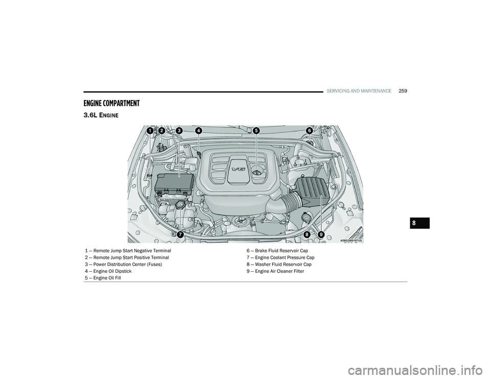
ENGINE COMPARTMENT
3.6L ENGINE
1 — Remote Jump Start Negative Terminal 6 — Brake Fluid Reservoir Cap
2 — Remote Jump Start Positive Terminal 7 — Engine Coolant Pressure Cap
3 — Power Distribution Center (Fuses) 8 — Washer Fluid Reservoir Cap
4 — Engine Oil Dipstick 9 — Engine Air Cleaner Filter
5 — Engine Oil Fill
8
22_WD_OM_EN_USC_t.book Page 259
Page 262 of 332
260SERVICING AND MAINTENANCE
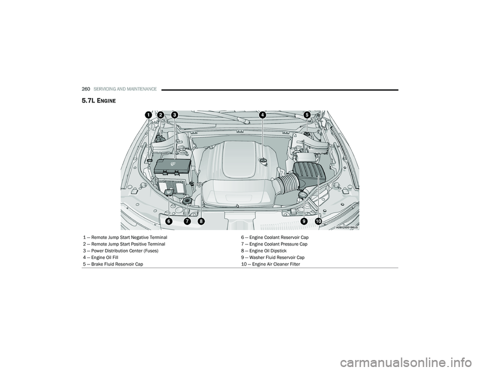
5.7L ENGINE
1 — Remote Jump Start Negative Terminal 6 — Engine Coolant Reservoir Cap
2 — Remote Jump Start Positive Terminal 7 — Engine Coolant Pressure Cap
3 — Power Distribution Center (Fuses) 8 — Engine Oil Dipstick
4 — Engine Oil Fill 9 — Washer Fluid Reservoir Cap
5 — Brake Fluid Reservoir Cap 10 — Engine Air Cleaner Filter
22_WD_OM_EN_USC_t.book Page 260
Page 269 of 332
SERVICING AND MAINTENANCE267
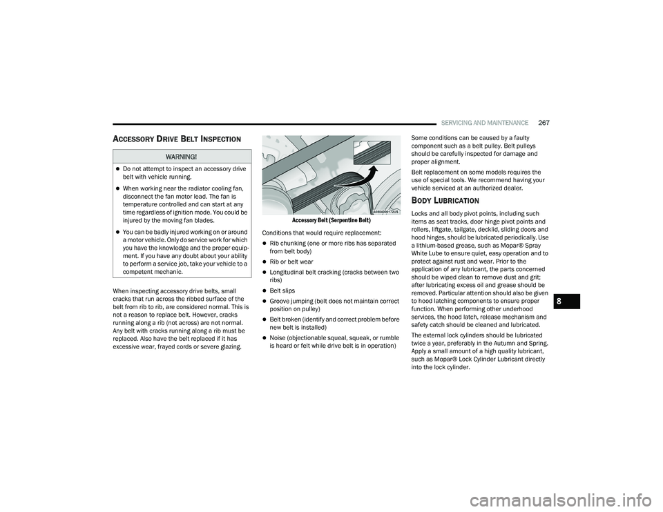
ACCESSORY DRIVE BELT INSPECTION
When inspecting accessory drive belts, small
cracks that run across the ribbed surface of the
belt from rib to rib, are considered normal. This is
not a reason to replace belt. However, cracks
running along a rib (not across) are not normal.
Any belt with cracks running along a rib must be
replaced. Also have the belt replaced if it has
excessive wear, frayed cords or severe glazing.
Accessory Belt (Serpentine Belt)
Conditions that would require replacement:
Rib chunking (one or more ribs has separated
from belt body)
Rib or belt wear
Longitudinal belt cracking (cracks between two
ribs)
Belt slips
Groove jumping (belt does not maintain correct
position on pulley)
Belt broken (identify and correct problem before
new belt is installed)
Noise (objectionable squeal, squeak, or rumble
is heard or felt while drive belt is in operation) Some conditions can be caused by a faulty
component such as a belt pulley. Belt pulleys
should be carefully inspected for damage and
proper alignment.
Belt replacement on some models requires the
use of special tools. We recommend having your
vehicle serviced at an authorized dealer.
BODY LUBRICATION
Locks and all body pivot points, including such
items as seat tracks, door hinge pivot points and
rollers, liftgate, tailgate, decklid, sliding doors and
hood hinges, should be lubricated periodically. Use
a lithium-based grease, such as Mopar® Spray
White Lube to ensure quiet, easy operation and to
protect against rust and wear. Prior to the
application of any lubricant, the parts concerned
should be wiped clean to remove dust and grit;
after lubricating excess oil and grease should be
removed. Particular attention should also be given
to hood latching components to ensure proper
function. When performing other underhood
services, the hood latch, release mechanism and
safety catch should be cleaned and lubricated.
The external lock cylinders should be lubricated
twice a year, preferably in the Autumn and Spring.
Apply a small amount of a high quality lubricant,
such as Mopar® Lock Cylinder Lubricant directly
into the lock cylinder.
WARNING!
Do not attempt to inspect an accessory drive
belt with vehicle running.
When working near the radiator cooling fan,
disconnect the fan motor lead. The fan is
temperature controlled and can start at any
time regardless of ignition mode. You could be
injured by the moving fan blades.
You can be badly injured working on or around
a motor vehicle. Only do service work for which
you have the knowledge and the proper equip
-
ment. If you have any doubt about your ability
to perform a service job, take your vehicle to a
competent mechanic.
8
22_WD_OM_EN_USC_t.book Page 267
Page 279 of 332
SERVICING AND MAINTENANCE277
FUSES
General Information
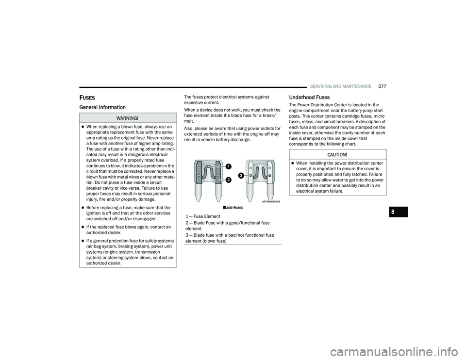
The fuses protect electrical systems against
excessive current.
When a device does not work, you must check the
fuse element inside the blade fuse for a break/
melt.
Also, please be aware that using power outlets for
extended periods of time with the engine off may
result in vehicle battery discharge.
Blade Fuses
Underhood Fuses
The Power Distribution Center is located in the
engine compartment near the battery jump start
posts. This center contains cartridge fuses, micro
fuses, relays, and circuit breakers. A description of
each fuse and component may be stamped on the
inside cover, otherwise the cavity number of each
fuse is stamped on the inside cover that
corresponds to the following chart.
WARNING!
When replacing a blown fuse, always use an
appropriate replacement fuse with the same
amp rating as the original fuse. Never replace
a fuse with another fuse of higher amp rating.
The use of a fuse with a rating other than indi -
cated may result in a dangerous electrical
system overload. If a properly rated fuse
continues to blow, it indicates a problem in the
circuit that must be corrected. Never replace a
blown fuse with metal wires or any other mate -
rial. Do not place a fuse inside a circuit
breaker cavity or vice versa. Failure to use
proper fuses may result in serious personal
injury, fire and/or property damage.
Before replacing a fuse, make sure that the
ignition is off and that all the other services
are switched off and/or disengaged.
If the replaced fuse blows again, contact an
authorized dealer.
If a general protection fuse for safety systems
(air bag system, braking system), power unit
systems (engine system, transmission
system) or steering system blows, contact an
authorized dealer.
1 — Fuse Element
2 — Blade Fuse with a good/functional fuse
element
3 — Blade fuse with a bad/not functional fuse
element (blown fuse)
CAUTION!
When installing the power distribution center
cover, it is important to ensure the cover is
properly positioned and fully latched. Failure
to do so may allow water to get into the power
distribution center and possibly result in an
electrical system failure.
8
22_WD_OM_EN_USC_t.book Page 277
Page 321 of 332
319
Disabled Vehicle Towing
................................ 253Disposal Antifreeze (Engine Coolant)....................... 273Door Ajar................................................... 90, 91Door Ajar Light.......................................... 90, 91Door Locks............................................... 22, 25Child-Protection Door Lock — Rear Doors.... 25Doors............................................................... 22Driver’s Seat Back Tilt..................................... 29Driving........................................................... 153
E
Economy (Fuel) Mode.................................... 105Electric Brake Control System....................... 183Anti-Lock Brake System............................. 182Electronic Roll Mitigation................. 184, 187Electric Remote Mirrors................................... 42Electrical Outlet, Auxiliary (Power Outlet)......... 66Electronic Speed Control (Cruise Control)...... 117Electronic Stability Control (ESC)...................184Electronic Throttle Control Warning Light........ 91Electronically Shifted Transfer Case.............. 109Emergency Gas Can Refueling...................... 248Emergency, In Case OfFreeing Vehicle When Stuck...................... 252Hazard Warning Flasher............................ 235Jacking...................................................... 239Jump Starting............................................ 246
Emission Control System Maintenance........... 98Engine........................................................... 259Air Cleaner................................................ 263Break-In Recommendations..................... 102Checking Oil Level.................................... 261Compartment.................................. 259, 260Compartment Identification............. 259, 260Cooling..................................................... 272Exhaust Gas Caution................................ 234Fails To Start............................................ 102Flooded, Starting...................................... 102Fuel Requirements.......................... 308, 311Jump Starting........................................... 246Oil.................................................... 262, 311Oil Filler Cap............................................. 259Oil Filter.................................................... 263Oil Selection........................... 262, 311, 312Oil Synthetic............................................. 263Starting........................................................ 99Enhanced Accident
Response Feature............................... 214, 254Ethanol......................................................... 309Exhaust Gas Cautions................................... 234Exhaust System................................... 234, 271Exterior Lights............................... 47, 234, 284
F
FiltersAir Cleaner
................................................ 263Air Conditioning........................ 61, 264, 265Engine Oil................................................. 263Engine Oil Disposal................................... 263Flashers........................................................ 235Hazard Warning........................................ 235Turn Signals.............................. 96, 234, 285Flash-To-Pass...................................................49Flooded Engine Starting................................ 102Fluid Capacities............................................ 311Fluid Leaks.................................................... 234Fluid Level ChecksBrake........................................................ 274Engine Oil................................................. 261Fluids And Lubricants.................................... 312Fog Lights..................................................... 285Fog Lights, Service........................................ 285Fold-Flat Seats.................................................29Folding Rear Seats...........................................31Forward Collision Warning............................ 191Four-Way Hazard Flasher.............................. 235Freeing A Stuck Vehicle................................. 252Front Axle (Differential)................................. 276
11
22_WD_OM_EN_USC_t.book Page 319