screen DODGE DURANGO 2023 User Guide
[x] Cancel search | Manufacturer: DODGE, Model Year: 2023, Model line: DURANGO, Model: DODGE DURANGO 2023Pages: 328, PDF Size: 13.82 MB
Page 59 of 328
GETTING TO KNOW YOUR VEHICLE57
REAR LOCK BUTTON
Press and release this button to lock out
the rear manual temperature controls
from adjusting the rear temperature and
blower settings. The LOCK REAR
indicator will illuminate when LOCK REAR is on.
Press and release this button again to exit the
feature.
FRONT CLIMATE BUTTON
Press and release to return to the Front
Climate Control Screen.
SYNC BUTTON
Press the SYNC (or SYNC To Driver)
button on the touchscreen to toggle the
SYNC feature on/off. The SYNC indicator
will illuminate when SYNC is on. SYNC is
used to synchronize the front passenger
temperature and rear passenger temperature,
mode, and blower settings with the driver
temperature, mode, and blower settings. Changing
the front passenger temperature or rear passenger
temperature, mode, or blower settings while in
SYNC will automatically exit this feature.
NOTE:The SYNC setting is only available on the touch -
screen.
REAR BLOWER CONTROL
Rear Blower Control is used to regulate
the amount of air forced through the rear
climate system. There are seven blower
speeds available. The speeds can be
selected using the buttons on the touchscreen.
Use the small blower icon (or blower icon with the
downward arrow) to reduce the blower setting, and
the large blower icon (or blower icon with the
upward arrow) to increase the blower setting.
Blower can also be selected by pressing the blower
bar area between the icons.
REAR MODE CONTROL
Select Mode by pressing one of the Mode
buttons on the touchscreen to change
the airflow distribution mode. The rear
airflow distribution mode can be
adjusted so air comes from the headliner outlets,
the floor outlets or both.
HEADLINER MODE
Air comes from the outlets in the
headliner. Each of these outlets can be
individually adjusted to direct the flow of
air. Moving the air vanes of the outlets to
one side shuts off the airflow.
BI-LEVEL MODE
Press this button on the touchscreen to
change the air distribution mode to
Bi-Level Mode. In Bi-Level Mode, air
comes from both the headliner outlets
and the floor outlets.
NOTE:In many temperature positions, the Bi-Level mode
is designed to provide cooler air out of the head -
liner outlets and warmer air from the floor outlets.
FLOOR MODE
Press this button on the touchscreen to
change the air distribution mode to Floor
Mode. In Floor Mode, air comes from the
floor outlets.
REAR CLIMATE CONTROL OFF BUTTON
To manually set the rear blower controls
to off, press the Rear Climate Control/
Blower Off button.
2
23_WD_OM_EN_USC_t.book Page 57
Page 60 of 328
58GETTING TO KNOW YOUR VEHICLE
Rear Automatic Temperature Control
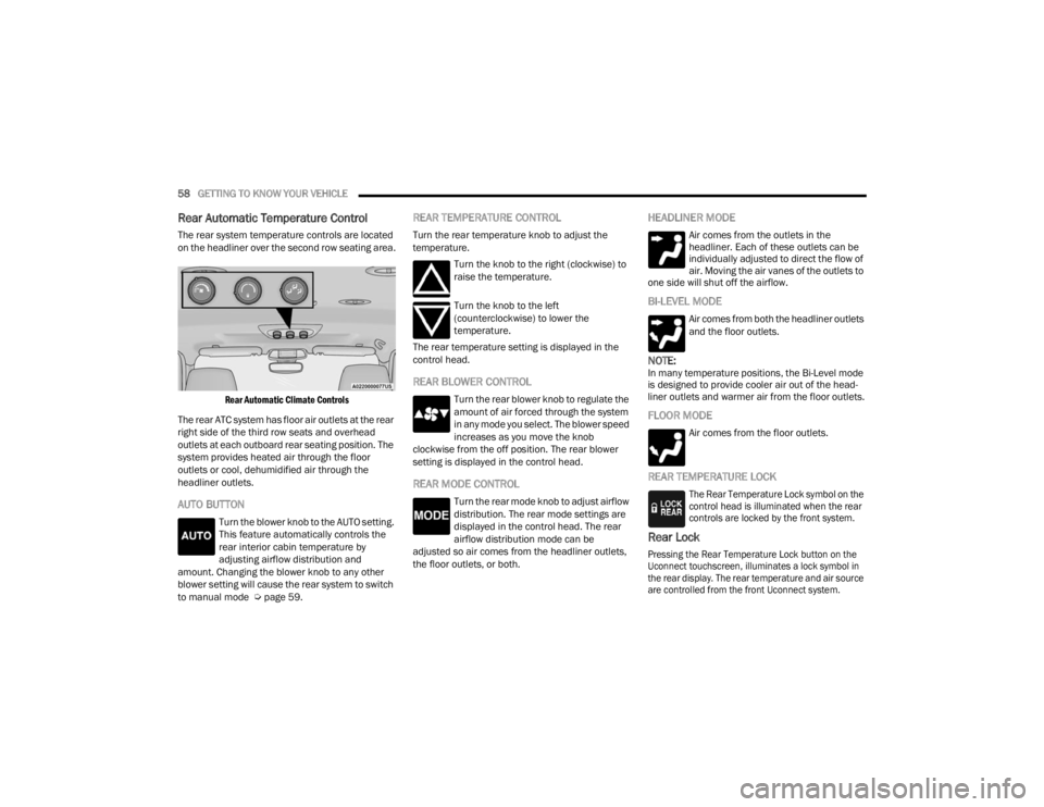
The rear system temperature controls are located
on the headliner over the second row seating area.
Rear Automatic Climate Controls
The rear ATC system has floor air outlets at the rear
right side of the third row seats and overhead
outlets at each outboard rear seating position. The
system provides heated air through the floor
outlets or cool, dehumidified air through the
headliner outlets.
AUTO BUTTON
Turn the blower knob to the AUTO setting.
This feature automatically controls the
rear interior cabin temperature by
adjusting airflow distribution and
amount. Changing the blower knob to any other
blower setting will cause the rear system to switch
to manual mode Ú page 59.
REAR TEMPERATURE CONTROL
Turn the rear temperature knob to adjust the
temperature.
Turn the knob to the right (clockwise) to
raise the temperature.
Turn the knob to the left
(counterclockwise) to lower the
temperature.
The rear temperature setting is displayed in the
control head.
REAR BLOWER CONTROL
Turn the rear blower knob to regulate the
amount of air forced through the system
in any mode you select. The blower speed
increases as you move the knob
clockwise from the off position. The rear blower
setting is displayed in the control head.
REAR MODE CONTROL
Turn the rear mode knob to adjust airflow
distribution. The rear mode settings are
displayed in the control head. The rear
airflow distribution mode can be
adjusted so air comes from the headliner outlets,
the floor outlets, or both.
HEADLINER MODE
Air comes from the outlets in the
headliner. Each of these outlets can be
individually adjusted to direct the flow of
air. Moving the air vanes of the outlets to
one side will shut off the airflow.
BI-LEVEL MODE
Air comes from both the headliner outlets
and the floor outlets.
NOTE:In many temperature positions, the Bi-Level mode
is designed to provide cooler air out of the head -
liner outlets and warmer air from the floor outlets.
FLOOR MODE
Air comes from the floor outlets.
REAR TEMPERATURE LOCK
The Rear Temperature Lock symbol on the
control head is illuminated when the rear
controls are locked by the front system.
Rear Lock
Pressing the Rear Temperature Lock button on the
Uconnect touchscreen, illuminates a lock symbol in
the rear display. The rear temperature and air source
are controlled from the front Uconnect system.
23_WD_OM_EN_USC_t.book Page 58
Page 61 of 328
GETTING TO KNOW YOUR VEHICLE59
Rear second row occupants can only adjust the
rear ATC control when the Rear Temperature Lock
button is turned off.
The rear ATC is located in the headliner, near the
center of the vehicle.
Press the Rear Temperature Lock button on the
Uconnect touchscreen. This turns off the Rear
Temperature Lock icon in the rear temperature
knob.
Rotate the Rear Blower, Rear Temperature and
the Rear Mode Control knobs to suit your
comfort needs.
ATC is selected by adjusting the rear blower
knob counterclockwise to AUTO.
Once the desired temperature is displayed, the
ATC System will automatically achieve and
maintain that comfort level. When the system is
set up for your comfort level, it is not necessary to
change the settings. You will experience the
greatest efficiency by simply allowing the system to
function automatically.
AUTOMATIC TEMPERATURE CONTROL
(ATC)
Automatic Operation
1. Push the AUTO button on the front Automatic
Temperature Control (ATC) Panel and the
word “AUTO” will illuminate in the front ATC
display, along with two temperatures for the driver and front passenger. The system will
then automatically regulate the amount of
airflow.
2. Adjust the temperature you would like the system to maintain, by adjusting the driver,
passenger, and rear temperatures. Once the
desired temperature is displayed, the system
will achieve and automatically maintain that
comfort level.
3. When the system is set up for your comfort level, it is not necessary to change the
settings. You will experience the greatest
efficiency by simply allowing the system to
function automatically.
NOTE:It is not necessary to move the temperature
settings. The system automatically adjusts the
temperature, mode and fan speed to provide
comfort as quickly as possible.
To provide you with maximum comfort in the
automatic mode, during cold start-ups, the blower
fan will remain on low until the engine warms up.
The fan will engage immediately if the Defrost
mode is selected, or by changing the front blower
knob setting.
Manual Operation Override
This system offers a full complement of manual
override features. The AUTO symbol in the front
ATC display will be turned off when the system is
being used in the manual mode.
NOTE:The system will not automatically sense the
presence of fog, mist or ice on the windshield.
Defrost mode must be manually selected to clear
the windshield and side glass.
CLIMATE VOICE RECOGNITION
Adjust vehicle temperatures hands-free and keep
everyone comfortable while you keep moving
ahead.
Push the VR button on the steering wheel. After the
beep, say one of the following commands:
“Set driver temperature to 70 degrees ”
“Set passenger temperature to 70 degrees ”
Did you know: Voice Command for Climate may
only be used to adjust the interior temperature of
your vehicle. Voice Command will not work to
adjust the heated seats or steering wheel if
equipped.
2
23_WD_OM_EN_USC_t.book Page 59
Page 66 of 328
64GETTING TO KNOW YOUR VEHICLE
Once the audio device is connected and
synchronized to the vehicle’s USB control system
(an external USB device may take a few minutes to
connect), the audio device starts charging and is
ready for use.
Once a device is connected to the USB port, it will
begin charging and is ready for use with the
system. Type C and Type A charge-only USB ports
can be used at the same time but cannot be used
simultaneously while playing media. When both
Type C and Type A charge-only USB ports are in use
they will be charged at a reduced rate.
NOTE:If the audio device battery is completely
discharged, it may not communicate with the USB
control system until a minimum charge is attained.
Leaving the audio device connected to the USB
control system may charge it to the required level.
Using This Feature
By using an external USB device to connect to the
USB port:
The audio device can be played on the vehicle’s
sound system, providing metadata (artist, track
title, album, etc.) information on the radio
display.
NOTE:Depending on track configuration, track infor -
mation may not be present on the radio display.
The audio device can be controlled using the
radio buttons to Play, Browse, and List the
contents.
The audio device battery charges when plugged
into the USB/AUX connector (if supported by the
specific audio device).
NOTE:For further information, refer to the Uconnect
Owner’s Manual Supplement.
Second Row USB Charging Port
Second Row USB Charging ports can be used for
charging purposes only. Use the connection cable
to connect an external USB device to the vehicle’s
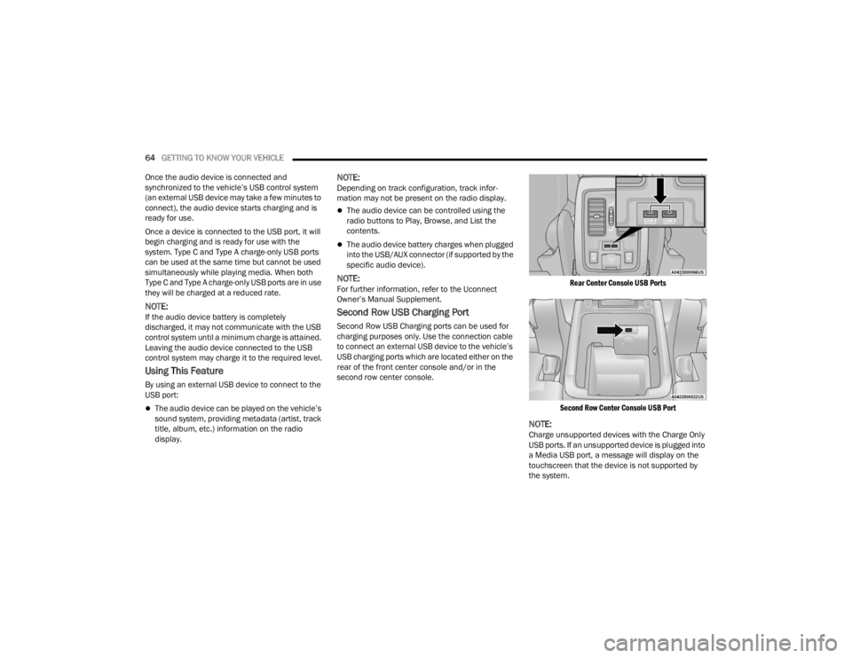
USB charging ports which are located either on the
rear of the front center console and/or in the
second row center console.
Rear Center Console USB Ports
Second Row Center Console USB Port
NOTE:Charge unsupported devices with the Charge Only
USB ports. If an unsupported device is plugged into
a Media USB port, a message will display on the
touchscreen that the device is not supported by
the system.
23_WD_OM_EN_USC_t.book Page 64
Page 82 of 328
80GETTING TO KNOW YOUR INSTRUMENT PANEL
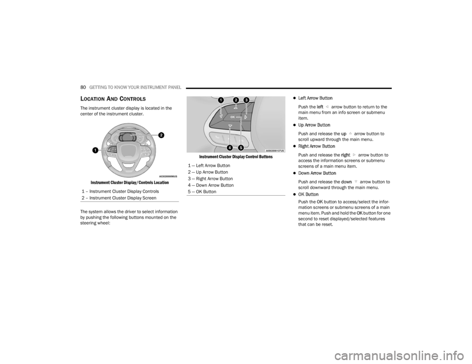
LOCATION AND CONTROLS
The instrument cluster display is located in the
center of the instrument cluster.
Instrument Cluster Display/Controls Location
The system allows the driver to select information
by pushing the following buttons mounted on the
steering wheel:
Instrument Cluster Display Control Buttons
Left Arrow Button
Push the left arrow button to return to the
main menu from an info screen or submenu
item.
Up Arrow Button
Push and release the up arrow button to
scroll upward through the main menu.
Right Arrow Button
Push and release the right arrow button to
access the information screens or submenu
screens of a main menu item.
Down Arrow Button
Push and release the down arrow button to
scroll downward through the main menu.
OK Button
Push the OK button to access/select the infor -
mation screens or submenu screens of a main
menu item. Push and hold the OK button for one
second to reset displayed/selected features
that can be reset.
1 – Instrument Cluster Display Controls
2 – Instrument Cluster Display Screen
1 — Left Arrow Button
2 — Up Arrow Button
3 — Right Arrow Button
4 — Down Arrow Button
5 — OK Button
23_WD_OM_EN_USC_t.book Page 80
Page 83 of 328
GETTING TO KNOW YOUR INSTRUMENT PANEL81
The instrument cluster display is located in the
center portion of the cluster and consist of multiple
sections:
Main Screen — The inner ring of the display will
illuminate in gray under normal conditions,
yellow for non critical warnings, red for critical
warnings, and white for on demand information.
Submenu Dots — Whenever there are
submenus available, the position within the
submenus is shown here.
Reconfigurable Telltales/Information
Gear Selector Status (PRND)
Driver Interactive Display (Compass, Temp,
Range to Empty, Trip A, Trip B, Average Fuel
Economy, Current Fuel Economy, Time, Trailer
Trip and Gain)
All-Wheel Drive (AWD) Status — If Equipped The instrument cluster display will normally display
the main menu or the screens of a selected feature
of the main menu. The main display area also
displays pop-up messages that consist of
approximately 60 possible warning or information
messages. These pop-up messages fall into
several categories:
Five Second Stored Messages
When the appropriate conditions occur, this
type of message takes control of the main
display area for five seconds and then returns to
the previous screen. Most of the messages of
this type are then stored (as long as the condi-
tion that activated it remains active) and can be
reviewed from the “Messages” main menu item.
Examples of this message type are “Right Front
Turn Signal Lamp Out” and “Low Tire Pressure.”
Unstored Messages
This message type is displayed indefinitely or
until the condition that activated the message is
cleared. Examples of this message type are
“Turn Signal On” (if a turn signal is left on) and
“Lights On” (if driver leaves the vehicle with the
lights on).
Unstored Messages Until RUN
These messages deal primarily with the Remote
Start feature. This message type is displayed
until the ignition is in the RUN state. Examples of
this message type are “Remote Start Canceled -
Door Ajar” and “Press Brake Pedal and Push
Button to Start.”
Five Second Unstored Messages
When the appropriate conditions occur, this
type of message takes control of the main
display area for five seconds and then returns to
the previous screen. An example of this
message type is “Automatic High Beams On.”
3
23_WD_OM_EN_USC_t.book Page 81
Page 84 of 328
82GETTING TO KNOW YOUR INSTRUMENT PANEL
ENGINE OIL LIFE RESET
Use this QR code to access your
digital experience.
Oil Change Required
Your vehicle is equipped with an
engine oil change indicator
system. The “Oil Change
Required” message will display in
the instrument cluster display for five seconds
after a single chime has sounded, to indicate the
next scheduled oil change interval. The engine oil
change indicator system is duty cycle based, which
means the engine oil change interval may
fluctuate, dependent upon your personal driving
style.
Unless reset, this message will continue to display
each time the ignition is placed in the ON/RUN
position. To turn off the message temporarily, push
and release the OK or arrow buttons. To reset the
oil change indicator system (after performing the
scheduled maintenance), refer to the following
procedure. Vehicles Equipped With Keyless Enter ‘n Go™ —
Ignition
Use the steering wheel instrument cluster display
controls for the following procedure(s):
1. Without pressing the brake pedal, push the
ENGINE START/STOP button and place the
ignition in the ON/RUN position (do not start
the engine).
2. Push and release the down arrow button to
scroll downward through the main menu to
“Vehicle Info.”
3. Push and release the right arrow button to
access the ”Oil Life” screen.
4. Push and hold the OK button to reset oil life. If
conditions are met, the gauge and numeric
display will update to show 100%. If conditions
are not met a pop-up message of “To reset oil
life engine must be off with ignition in run” will
be displayed (for five seconds), and the user
will remain at the Oil Life screen.
5. Push and release the up or down arrow
button to exit the submenu screen.
NOTE:If the indicator message illuminates when you start
the vehicle, the oil change indicator system did not
reset. If necessary, repeat this procedure.
Secondary Method Of Resetting Engine Oil Life
1. Without pressing the brake pedal, push the ENGINE START/STOP button and place the
ignition to the ON/RUN position (do not start
the engine).
2. Fully press the accelerator pedal, slowly, three times within 10 seconds.
3. Without pushing the brake pedal, push the ENGINE START/STOP button once to return the
ignition to the OFF position.
NOTE:If the indicator message illuminates when you start
the vehicle, the oil change indicator system did not
reset. If necessary, repeat this procedure.
23_WD_OM_EN_USC_t.book Page 82
Page 85 of 328
GETTING TO KNOW YOUR INSTRUMENT PANEL83
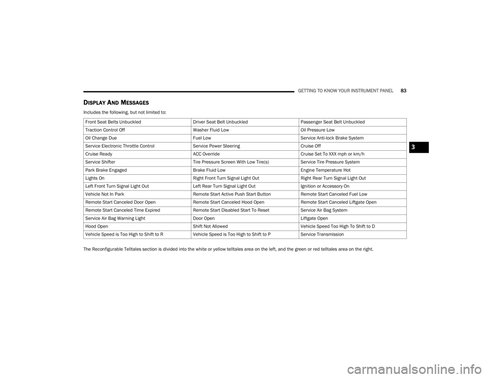
DISPLAY AND MESSAGES
Includes the following, but not limited to:
The Reconfigurable Telltales section is divided into the white or yellow telltales area on the left, and the green or red telltales area on the right.Front Seat Belts Unbuckled
Driver Seat Belt UnbuckledPassenger Seat Belt Unbuckled
Traction Control Off Washer Fluid LowOil Pressure Low
Oil Change Due Fuel LowService Anti-lock Brake System
Service Electronic Throttle Control Service Power SteeringCruise Off
Cruise Ready ACC OverrideCruise Set To XXX mph or km/h
Service Shifter Tire Pressure Screen With Low Tire(s)Service Tire Pressure System
Park Brake Engaged Brake Fluid LowEngine Temperature Hot
Lights On Right Front Turn Signal Light OutRight Rear Turn Signal Light Out
Left Front Turn Signal Light Out Left Rear Turn Signal Light OutIgnition or Accessory On
Vehicle Not In Park Remote Start Active Push Start ButtonRemote Start Canceled Fuel Low
Remote Start Canceled Door Open Remote Start Canceled Hood OpenRemote Start Canceled Liftgate Open
Remote Start Canceled Time Expired Remote Start Disabled Start To ResetService Air Bag System
Service Air Bag Warning Light Door OpenLiftgate Open
Hood Open Shift Not AllowedVehicle Speed Too High To Shift to D
Vehicle Speed is Too High to Shift to R Vehicle Speed is Too High to Shift to PService Transmission
3
23_WD_OM_EN_USC_t.book Page 83
Page 88 of 328
86GETTING TO KNOW YOUR INSTRUMENT PANEL
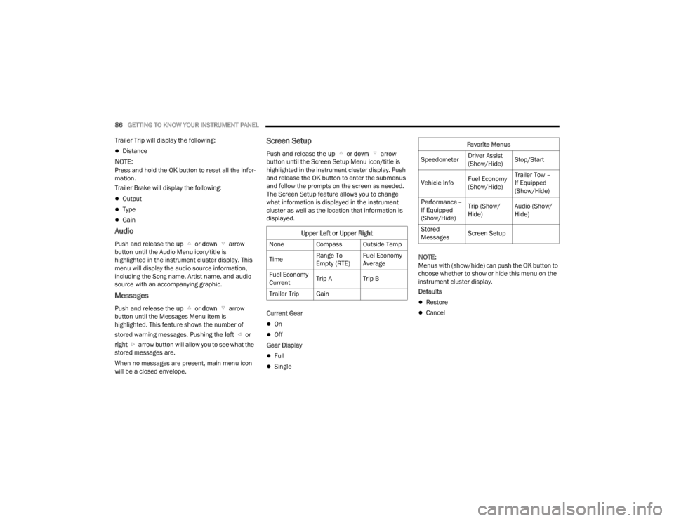
Trailer Trip will display the following:
Distance
NOTE:Press and hold the OK button to reset all the infor -
mation.
Trailer Brake will display the following:
Output
Type
Gain
Audio
Push and release the up or down arrow
button until the Audio Menu icon/title is
highlighted in the instrument cluster display. This
menu will display the audio source information,
including the Song name, Artist name, and audio
source with an accompanying graphic.
Messages
Push and release the up or down arrow
button until the Messages Menu item is
highlighted. This feature shows the number of
stored warning messages. Pushing the left or
right arrow button will allow you to see what the
stored messages are.
When no messages are present, main menu icon
will be a closed envelope.
Screen Setup
Push and release the up or down arrow
button until the Screen Setup Menu icon/title is
highlighted in the instrument cluster display. Push
and release the OK button to enter the submenus
and follow the prompts on the screen as needed.
The Screen Setup feature allows you to change
what information is displayed in the instrument
cluster as well as the location that information is
displayed.
Current Gear
On
Off
Gear Display
Full
Single
NOTE:Menus with (show/hide) can push the OK button to
choose whether to show or hide this menu on the
instrument cluster display.
Defaults
Restore
Cancel
Upper Left or Upper Right
None Compass Outside Temp
Time Range To
Empty (RTE)Fuel Economy
Average
Fuel Economy
Current Trip A Trip B
Trailer Trip Gain
Favorite Menus
Speedometer Driver Assist
(Show/Hide)Stop/Start
Vehicle Info Fuel Economy
(Show/Hide)Trailer Tow –
If Equipped
(Show/Hide)
Performance –
If Equipped
(Show/Hide) Trip (Show/
Hide)
Audio (Show/
Hide)
Stored
Messages Screen Setup
23_WD_OM_EN_USC_t.book Page 86
Page 115 of 328
STARTING AND OPERATING113
4. Allow vehicle to sit and cool for at least 30 minutes. If an infrared thermal gun is
available, allow rotors to cool to 200°F
(93.3°C) before returning to the track.
5. There should be a thin layer of ash when inspecting the brake pads. Having the ash
layer go more than half the thickness of the
pad material is a sign of an overly aggressive
burnish.
6. Occasionally, a second burnish session is required. If the brake pads begin to emit an
odor during the next track session, reduce
vehicle speed and braking deceleration rate to
burnish targets and follow steps 2-4.
7. New brake pads installed on old rotors require a burnish. New rotors installed with old brake
pads should be burnished at the track or
driven for 300 miles (485 km) of city driving to
develop an adequate lining transfer layer on
the rotor surface prior to track use.
8. Rotors that pulsate during track use should be replaced.
NOTE:Resurfacing of the rotors is not recommended, as
it removes mass from the rotor, reducing its
thermal capacity. Resurfacing also thins the rotor
cheek, making it less robust and increasing the
likelihood of pulsation in further track use.
FUEL SAVER TECHNOLOGY 5.7L ONLY —
IF EQUIPPED
This feature offers improved fuel economy by
shutting off four of the engine's eight cylinders
during light load and cruise conditions. The system
is automatic with no driver inputs.
NOTE:This system may take some time to return to full
functionality after a battery disconnect.
POWER STEERING
The electric power steering system will provide
increased vehicle response and ease of
maneuverability. The power steering system
adapts to different driving conditions and adjusts
accordingly. Alternate electric power steering efforts can be
selected through the Uconnect System
Ú
page 153.
If the Electric Power Steering warning icon is
displayed and the “Service Power Steering” or the
“Power Steering Assist Off – Service System”
message is displayed within the instrument cluster
display, this indicates the vehicle needs to be
taken to the dealer for service Ú page 88.
NOTE:
Even if the power steering assistance is no
longer operational, it is still possible to steer the
vehicle. Under these conditions there will be a
substantial increase in steering effort, espe -
cially at low speeds and during parking maneu -
vers.
If the condition persists, see an authorized
dealer for service.
If the Steering icon is displayed and the “Power
Steering System Over Temp” message is displayed
on the instrument cluster screen, this indicates an
over temperature condition in the power steering
system. Once driving conditions are safe, pull over
and let the vehicle idle for a few moments until the
icon and message turn off.
WARNING!
Continued operation with reduced assist could
pose a safety risk to yourself and others. Service
should be obtained as soon as possible.
4
23_WD_OM_EN_USC_t.book Page 113