ECO mode DODGE DURANGO 2023 Service Manual
[x] Cancel search | Manufacturer: DODGE, Model Year: 2023, Model line: DURANGO, Model: DODGE DURANGO 2023Pages: 328, PDF Size: 13.82 MB
Page 182 of 328
180SAFETY
(Continued)
Electronic Stability Control (ESC)
ESC enhances directional control and stability of
the vehicle under various driving conditions. ESC
corrects for oversteering or understeering of the
vehicle by applying the brake of the appropriate
wheel(s) to counteract the previous conditions.
Engine power may also be reduced to help the
vehicle maintain the desired path.
Oversteer — when the vehicle is turning more
than appropriate for the steering wheel position.
Understeer — when the vehicle is turning less
than appropriate for the steering wheel position.
ESC uses sensors in the vehicle to determine the
vehicle path intended by the driver and compares
it to the actual path of the vehicle. When the actual
path does not match the intended path, ESC
applies the brake of the appropriate wheel to
assist in counteracting the oversteer or understeer
condition.
The ESC Activation/Malfunction Indicator Light
located in the instrument cluster will start to flash
as soon as the ESC system becomes active. The
ESC Activation/Malfunction Indicator Light also
flashes when the Traction Control System (TCS) is
active. If the ESC Activation/Malfunction Indicator
Light begins to flash during acceleration, ease up
on the accelerator and apply as little throttle as
possible. Be sure to adapt your speed and driving
to the prevailing road conditions.
ESC Operating Modes
Depending upon model and mode of operation, the
ESC system may have multiple operating modes.
ESC On
This is the normal operating mode for the ESC.
Whenever the vehicle is started, the ESC system
will be in this mode. This mode should be used for
most driving conditions. Alternate ESC modes
should only be used for specific reasons as noted
in the following paragraphs.
WARNING!
Electronic Stability Control (ESC) cannot
prevent the natural laws of physics from
acting on the vehicle, nor can it increase the
traction afforded by prevailing road condi -
tions. ESC cannot prevent accidents, including
those resulting from excessive speed in turns,
driving on very slippery surfaces, or hydro -
planing. ESC also cannot prevent accidents
resulting from loss of vehicle control due to
inappropriate driver input for the conditions.
Only a safe, attentive, and skillful driver can
prevent accidents. The capabilities of an ESC
equipped vehicle must never be exploited in a
reckless or dangerous manner which could
jeopardize the user’s safety or the safety of
others.Vehicle modifications, or failure to properly
maintain your vehicle, may change the
handling characteristics of your vehicle, and
may negatively affect the performance of the
ESC system. Changes to the steering system,
suspension, braking system, tire type and size
or wheel size may adversely affect ESC perfor -
mance. Improperly inflated and unevenly worn
tires may also degrade ESC performance. Any
vehicle modification or poor vehicle mainte -
nance that reduces the effectiveness of the
ESC system can increase the risk of loss of
vehicle control, vehicle rollover, personal
injury and death.
WARNING!
23_WD_OM_EN_USC_t.book Page 180
Page 183 of 328
SAFETY181
Partial Off
This mode may be useful if the vehicle becomes
stuck. This mode may modify TCS and ESC
thresholds for activation, which allows for more
wheel spin than normally allowed.
To enter the “Partial Off” mode, momentarily push
the ESC OFF button and the ESC OFF Indicator
Light will illuminate. To turn the ESC on again,
momentarily push the ESC OFF button and the ESC
OFF Indicator Light will turn off.
NOTE:For vehicles with multiple partial ESC modes, the
push and release of the button may toggle the ESC
modes. Multiple attempts may be required to
return to "ESC On" mode.
ESC Activation/Malfunction Indicator Light
And ESC OFF Indicator Light
The ESC Activation/Malfunction Indicator
Light in the instrument cluster will come
on when the ignition is placed in the ON/
RUN mode. It should go out with the
engine running. If the ESC Activation/Malfunction
Indicator Light comes on continuously with the
engine running, a malfunction has been detected
in the ESC system. If this light remains on after
several ignition cycles, and the vehicle has been
driven several miles (kilometers) at speeds greater
than 30 mph (48 km/h), see an authorized dealer
as soon as possible to have the problem
diagnosed and corrected.
The ESC Activation/Malfunction Indicator Light
starts to flash as soon as the tires lose traction and
the ESC system becomes active. The ESC
Activation/Malfunction Indicator Light also flashes
when TCS is active. If the ESC Activation/
Malfunction Indicator Light begins to flash during
acceleration, ease up on the accelerator and apply
as little throttle as possible. Be sure to adapt your
speed and driving to the prevailing road conditions.
The ESC OFF Indicator Light indicates
that the Electronic Stability Control (ESC)
is in a reduced mode.
NOTE:
The ESC Activation/Malfunction Indicator Light
and the ESC OFF Indicator Light come on
momentarily each time the ignition placed in the
ON position.
Each time the ignition is placed in the ON posi -
tion, the ESC system will be on even if it was
turned off previously.
The ESC system will make buzzing or clicking
sounds when it is active. This is normal; the
sounds will stop when ESC becomes inactive
following the maneuver that caused the ESC
activation.
Hill Start Assist (HSA)
HSA is designed to mitigate roll back from a
complete stop while on an incline. If the driver
releases the brake while stopped on an incline,
HSA will continue to hold the brake pressure for a
short period. If the driver does not apply the
throttle before this time expires, the system will
release brake pressure and the vehicle will roll
down the hill as normal.
The following conditions must be met in order for
HSA to activate:
The feature must be enabled.
The vehicle must be stopped.
WARNING!
When in “Partial Off” mode, the TCS function -
ality of ESC, except for the limited slip feature
described in the TCS section, has been
disabled and the ESC OFF Indicator Light will
be illuminated. When in “Partial Off” mode,
the engine power reduction feature of TCS is
disabled, and the enhanced vehicle stability
offered by the ESC system is reduced.
Trailer Sway Control (TSC) is disabled when
the ESC system is in the “Partial Off” mode.
6
23_WD_OM_EN_USC_t.book Page 181
Page 185 of 328
SAFETY183
spinning wheel. This will allow more engine power
to be applied to the wheel that is not spinning. BLD
may remain enabled even if TCS and ESC are in
reduced modes.
Trailer Sway Control (TSC)
TSC uses sensors in the vehicle to recognize an
excessively swaying trailer and will take the
appropriate actions to attempt to stop the sway.
Note that TSC cannot stop all trailers from swaying.
Always use caution when towing a trailer and follow
the trailer tongue weight recommendations
Ú page 137.
When TSC is functioning, the ESC Activation/
Malfunction Indicator Light will flash, the engine
power may be reduced and you may feel the
brakes being applied to individual wheels to
attempt to stop the trailer from swaying. TSC is
disabled when the ESC system is in the “Partial
Off” mode.
AUXILIARY DRIVING SYSTEMS
BLIND SPOT MONITORING (BS M) —
I
F EQUIPPED
BSM uses two radar sensors, located inside the
rear fascia/bumper, to detect highway licensable
vehicles (automobiles, trucks, motorcycles, etc.)
that enter the blind spot zones from the rear/front/
side of the vehicle.
Rear Detection Zones
When the vehicle is started, the BSM Warning Light
will momentarily illuminate in both outside
rearview mirrors to let the driver know that the
system is operational. The BSM system sensors
operate when the vehicle is in any forward gear. The BSM detection zone covers approximately one
lane in width, on both sides of the vehicle 12 ft
(3.8 m). The zone length starts at the side of the
vehicle, near the B-pillar, and extends
approximately 10 ft (3 m) beyond the rear fascia/
bumper of the vehicle. The BSM system monitors
the detection zones on both sides of the vehicle
when the vehicle speed has reached
approximately 6 mph (10 km/h) or higher and will
alert the driver of vehicles in these areas.
NOTE:
The BSM system DOES NOT alert the driver
about rapidly approaching vehicles that are
outside the detection zones.
The BSM system detection zone DOES NOT
change if your vehicle is towing a trailer. There
-
fore, visually verify the adjacent lane is clear for
both your vehicle and trailer before making a
lane change. If the trailer or other object (i.e.,
bicycle, sports equipment) extends beyond the
side of your vehicle, this may result in random
false detections on the trailer, and false chimes
when the turn signal is used Ú page 153.
The BSM system can become blocked if snow,
ice, mud, or other road contaminations accumu -
late on the rear fascia/bumper where the radar
sensors are located. The system may also
detect blockage if the vehicle is operated in
areas with extremely low radar returns such as
a desert or parallel to a large elevation drop. If
WARNING!
If TSC activates while driving, slow the vehicle
down, stop at the nearest safe location, and
adjust the trailer load to eliminate trailer sway.
6
23_WD_OM_EN_USC_t.book Page 183
Page 193 of 328
SAFETY191
that has a pressure below the low-pressure
warning limit, upon the next ignition switch cycle,
the TPMS Warning Light will remain on, a chime will
sound, and the instrument cluster display will still
display a pressure value in the different color
graphic display and an “Inflate to XX” message will
be displayed. After driving the vehicle for up to
20 minutes above 15 mph (24 km/h), the TPMS
Warning Light will flash on and off for 75 seconds
and then remain on solid. In addition, the
instrument cluster display will display a “SERVICE
TPM SYSTEM" message for five seconds and then
display dashes (--) in place of the pressure value.
For each subsequent ignition switch cycle, a chime
will sound, the TPMS Warning Light will flash on
and off for 75 seconds and then remain on solid,
and the instrument cluster display will display a
"SERVICE TPM SYSTEM" message for five seconds
and then display dashes (--) in place of the
pressure value. Once you repair or replace the
original road tire, and reinstall it on the vehicle in
place of the spare tire, the TPMS will update auto -
matically.
In addition, the TPMS Warning Light will turn off
and the graphic in the instrument cluster display
will display a new pressure value instead of dashes
(--), as long as no tire pressure is below the
low-pressure warning limit in any of the four active
road tires. The vehicle may need to be driven for up
to 20 minutes above 15 mph (24 km/h) in order
for the TPMS to receive this information.
TPMS Deactivation — If Equipped
The TPMS can be deactivated if replacing all four
wheel and tire assemblies (road tires) with wheel
and tire assemblies that do not have TPMS
sensors, such as when installing winter wheel and
tire assemblies on your vehicle.
To deactivate the TPMS, first, replace all four wheel
and tire assemblies (road tires) with tires not
equipped with TPMS sensors. Then, drive the
vehicle for 20 minutes above 15 mph (24 km/h).
The TPMS will chime, the TPMS Warning Light will
flash on and off for 75 seconds and then remain
on. The instrument cluster will display the
“SERVICE TPM SYSTEM” message and then
display dashes (--) in place of the pressure values.
Beginning with the next ignition cycle, the TPMS
will no longer chime or display the “SERVICE TPM
SYSTEM” message in the instrument cluster but
dashes (--) will remain in place of the pressure
values.
To reactivate the TPMS, replace all four wheel and
tire assemblies (road tires) with tires equipped with
TPMS sensors. Then, drive the vehicle for up to
20 minutes above 15 mph (24 km/h). The TPMS
will chime, the TPMS Warning Light will flash on
and off for 75 seconds and then turn off. The
instrument cluster will display the “SERVICE TPM
SYSTEM” message and then display pressure values in place of the dashes. On the next ignition
cycle the "SERVICE TPM SYSTEM" message will no
longer be displayed as long as no system fault
exists.
OCCUPANT RESTRAINT SYSTEMS
Some of the most important safety features in your
vehicle are the restraint systems:
OCCUPANT RESTRAINT SYSTEMS
F
EATURES
Seat Belt Systems
Supplemental Restraint Systems (SRS) Air Bags
Child Restraints
Some of the safety features described in this
section may be standard equipment on some
models, or may be optional equipment on others. If
you are not sure, ask an authorized dealer.
IMPORTANT SAFETY PRECAUTIONS
Please pay close attention to the information in
this section. It tells you how to use your restraint
system properly, to keep you and your passengers
as safe as possible.
6
23_WD_OM_EN_USC_t.book Page 191
Page 200 of 328
198SAFETY
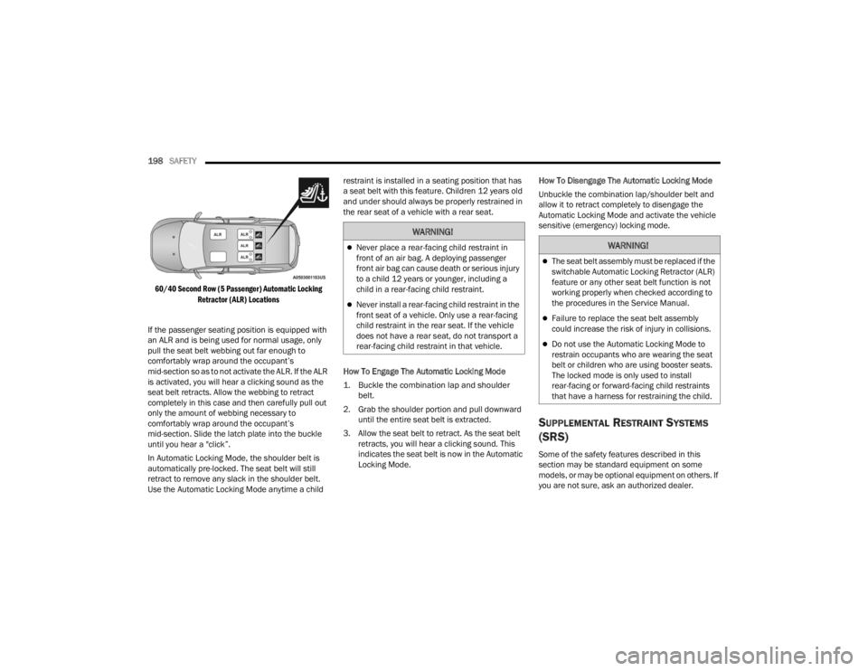
60/40 Second Row (5 Passenger) Automatic Locking Retractor (ALR) Locations
If the passenger seating position is equipped with
an ALR and is being used for normal usage, only
pull the seat belt webbing out far enough to
comfortably wrap around the occupant’s
mid-section so as to not activate the ALR. If the ALR
is activated, you will hear a clicking sound as the
seat belt retracts. Allow the webbing to retract
completely in this case and then carefully pull out
only the amount of webbing necessary to
comfortably wrap around the occupant’s
mid-section. Slide the latch plate into the buckle
until you hear a "click”.
In Automatic Locking Mode, the shoulder belt is
automatically pre-locked. The seat belt will still
retract to remove any slack in the shoulder belt.
Use the Automatic Locking Mode anytime a child restraint is installed in a seating position that has
a seat belt with this feature. Children 12 years old
and under should always be properly restrained in
the rear seat of a vehicle with a rear seat.
How To Engage The Automatic Locking Mode
1. Buckle the combination lap and shoulder
belt.
2. Grab the shoulder portion and pull downward until the entire seat belt is extracted.
3. Allow the seat belt to retract. As the seat belt retracts, you will hear a clicking sound. This
indicates the seat belt is now in the Automatic
Locking Mode. How To Disengage The Automatic Locking Mode
Unbuckle the combination lap/shoulder belt and
allow it to retract completely to disengage the
Automatic Locking Mode and activate the vehicle
sensitive (emergency) locking mode.
SUPPLEMENTAL RESTRAINT SYSTEMS
(SRS)
Some of the safety features described in this
section may be standard equipment on some
models, or may be optional equipment on others. If
you are not sure, ask an authorized dealer.
WARNING!
Never place a rear-facing child restraint in
front of an air bag. A deploying passenger
front air bag can cause death or serious injury
to a child 12 years or younger, including a
child in a rear-facing child restraint.
Never install a rear-facing child restraint in the
front seat of a vehicle. Only use a rear-facing
child restraint in the rear seat. If the vehicle
does not have a rear seat, do not transport a
rear-facing child restraint in that vehicle.
WARNING!
The seat belt assembly must be replaced if the
switchable Automatic Locking Retractor (ALR)
feature or any other seat belt function is not
working properly when checked according to
the procedures in the Service Manual.
Failure to replace the seat belt assembly
could increase the risk of injury in collisions.
Do not use the Automatic Locking Mode to
restrain occupants who are wearing the seat
belt or children who are using booster seats.
The locked mode is only used to install
rear-facing or forward-facing child restraints
that have a harness for restraining the child.
23_WD_OM_EN_USC_t.book Page 198
Page 207 of 328
SAFETY205
The Air Bag Warning Light in the instrument
panel will turn on whenever the OCS is unable to
classify the front passenger seat status. A
malfunction in the OCS may affect the operation of
the air bag system.
If the Air Bag Warning Light does not come on,
or stays on after you start the vehicle, or it comes
on as you drive, take the vehicle to an authorized
dealer for service immediately.
The passenger seat assembly contains critical OCS
components that may affect the Passenger
Advanced Front Air Bag inflation. In order for the
OCS to properly classify the seated weight of a
front seat passenger, the OCS components must
function as designed. Do not make any
modifications to the front passenger seat
components, assembly, or to the seat cover. If the
seat, trim cover, or cushion needs service for any
reason, take the vehicle to an authorized dealer.
Only FCA US LLC approved seat accessories may
be used.
The following requirements must be strictly
followed:
Do not modify the front passenger seat
assembly or components in any way.
Do not use prior or future model year seat
covers or cushions not designated by FCA US
LLC for the specific model being repaired. Always use the correct seat cover and cushion
specified for the vehicle.
Do not replace the seat cover or cushion with an
aftermarket seat cover or cushion.
Do not add a secondary seat cover or mat.
At no time should any Supplemental Restraint
System (SRS) component or SRS related
component or fastener be modified or replaced
with any part except those which are approved
by FCA US LLC.
Knee Impact Bolsters
The Knee Impact Bolsters help protect the knees
of the driver and front passenger, and position the
front occupants for improved interaction with the
front air bags.
Supplemental Driver Knee Air Bag
This vehicle is equipped with a Supplemental
Driver Knee Air Bag mounted in the instrument
panel below the steering column. The
Supplemental Driver Knee Air Bag provides
enhanced protection during a frontal impact by
working together with the seat belts,
pretensioners, and front air bags.
WARNING!
Unapproved modifications or service proce-
dures to the passenger seat assembly, its
related components, seat cover or cushion
may inadvertently change the air bag deploy
-
ment in case of a frontal collision. This could
result in death or serious injury to the front
passenger if the vehicle is involved in a colli -
sion. A modified vehicle may not comply with
required Federal Motor Vehicle Safety Stan -
dards (FMVSS) and/or Canadian Motor
Vehicle Safety Standards (CMVSS).
If it is necessary to modify the air bag system
for persons with disabilities, contact an autho -
rized dealer.
WARNING!
Do not drill, cut, or tamper with the knee
impact bolsters in any way.
Do not mount any accessories to the knee
impact bolsters such as alarm lights, stereos,
citizen band radios, etc.
6
23_WD_OM_EN_USC_t.book Page 205
Page 223 of 328
SAFETY221
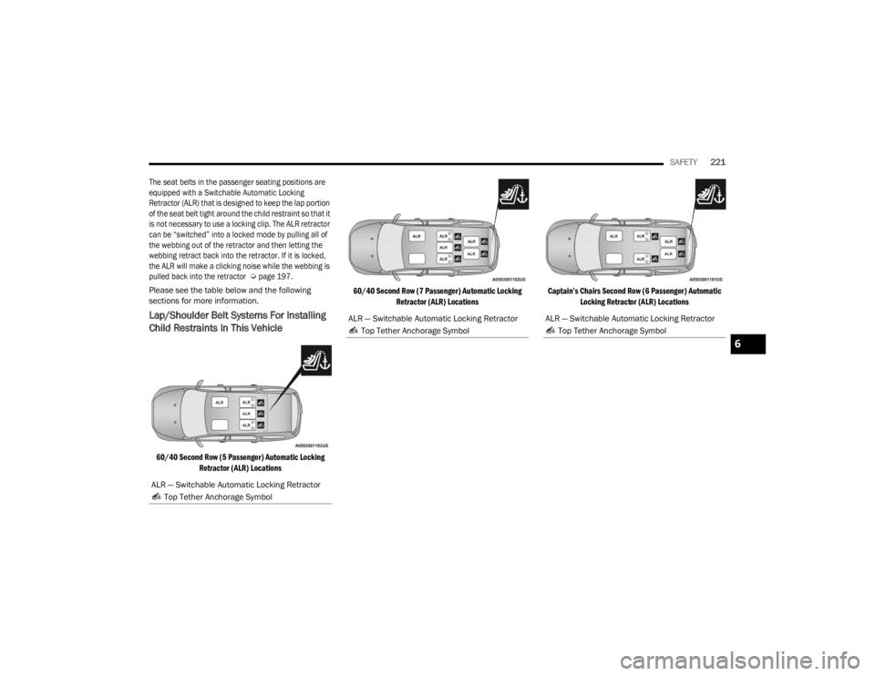
The seat belts in the passenger seating positions are
equipped with a Switchable Automatic Locking
Retractor (ALR) that is designed to keep the lap portion
of the seat belt tight around the child restraint so that it
is not necessary to use a locking clip. The ALR retractor
can be “switched” into a locked mode by pulling all of
the webbing out of the retractor and then letting the
webbing retract back into the retractor. If it is locked,
the ALR will make a clicking noise while the webbing is
pulled back into the retractor
Ú
page 197.
Please see the table below and the following
sections for more information.
Lap/Shoulder Belt Systems For Installing
Child Restraints In This Vehicle
60/40 Second Row (5 Passenger) Automatic Locking Retractor (ALR) Locations 60/40 Second Row (7 Passenger) Automatic Locking
Retractor (ALR) Locations Captain’s Chairs Second Row (6 Passenger) Automatic
Locking Retractor (ALR) Locations
ALR — Switchable Automatic Locking Retractor Top Tether Anchorage Symbol
ALR — Switchable Automatic Locking Retractor Top Tether Anchorage SymbolALR — Switchable Automatic Locking Retractor Top Tether Anchorage Symbol
6
23_WD_OM_EN_USC_t.book Page 221
Page 224 of 328
222SAFETY
Installing A Child Restraint With A
Switchable Automatic Locking Retractor
(ALR):
Child restraint systems are designed to be secured
in vehicle seats by lap belts or the lap belt portion
of a lap/shoulder belt.
1. Place the child seat in the center of the
seating position. If the second row seat can
be reclined, you may recline the seat and/or
raise the head restraint (if adjustable) to get a
better fit. If the rear seat can be moved
forward and rearward in the vehicle, you may
wish to move it to its rear-most position to
make room for the child seat. You may also
move the front seat forward to allow more
room for the child seat.
2. Pull enough of the seat belt webbing from the retractor to pass it through the belt path of the
child restraint. Do not twist the belt webbing in
the belt path. 3. Slide the latch plate into the buckle until you
hear a “click.”
4. Pull on the webbing to make the lap portion tight against the child seat.
5. To lock the seat belt, pull down on the shoulder part of the belt until you have pulled all the
seat belt webbing out of the retractor. Then,
allow the webbing to retract back into the
retractor. As the webbing retracts, you will hear
a clicking sound. This means the seat belt is
now in the Automatic Locking mode.
Frequently Asked Questions About Installing Child Restraints With Seat Belts
What is the weight limit (child’s weight + weight of
the child restraint) for using the Tether Anchor with
the seat belt to attach a forward-facing child
restraint? Weight limit of the Child RestraintAlways use the tether anchor when using the seat
belt to install a forward-facing child restraint, up to
the recommended weight limit of the child
restraint.
Can the rear-facing child restraint touch the back of
the front passenger seat? YesContact between the front passenger seat and the
child restraint is allowed, if the child restraint
manufacturer also allows contact.
Can the rear head restraints be removed? No
Can the buckle stalk be twisted to tighten the seat
belt against the belt path of the child restraint? NoDo not twist the buckle stalk in a seating position
with an ALR retractor.
WARNING!
Improper installation or failure to properly
secure a child restraint can lead to failure of
the restraint. The child could be badly injured
or killed.
Follow the child restraint manufacturer’s
directions exactly when installing an infant or
child restraint.
23_WD_OM_EN_USC_t.book Page 222
Page 228 of 328
226SAFETY
(Continued)
SAFETY CHECKS YOU SHOULD MAKE
I
NSIDE THE VEHICLE
Seat Belts
Inspect the seat belt system periodically, checking
for cuts, frays, and loose parts. Damaged parts
must be replaced immediately. Do not
disassemble or modify the system.
If your vehicle is involved in a collision, or if you
have questions regarding seat belt or retractor
conditions, take your vehicle to an authorized FCA
dealer or authorized FCA Certified Collision Care
Program facility for inspection.
Air Bag Warning Light
The Air Bag Warning Light will turn on for
four to eight seconds as a bulb check
when the ignition switch is first placed in
the ON/RUN mode. If the light is either not
on during starting, stays on, or turns on while driving,
have the system inspected at an authorized dealer
as soon as possible. After the bulb check, this light
will illuminate with a single chime when a fault with
the Air Bag System has been detected. It will stay on
until the fault is removed. If the light comes on
intermittently or remains on while driving, have an
authorized dealer service the vehicle immediately
Ú
page 191.
Defroster
Check operation by selecting the defrost mode and
place the blower control on high speed. You should
be able to feel the air directed against the
windshield. See an authorized dealer for service if
your defroster is inoperable.
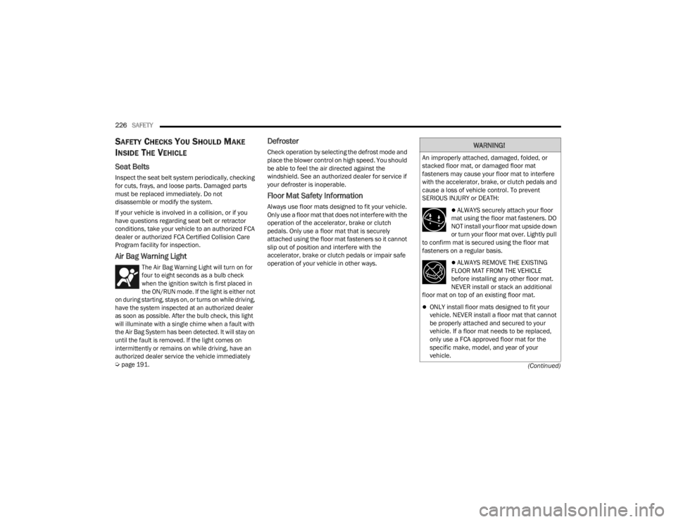
Floor Mat Safety Information
Always use floor mats designed to fit your vehicle.
Only use a floor mat that does not interfere with the
operation of the accelerator, brake or clutch
pedals. Only use a floor mat that is securely
attached using the floor mat fasteners so it cannot
slip out of position and interfere with the
accelerator, brake or clutch pedals or impair safe
operation of your vehicle in other ways.
WARNING!
An improperly attached, damaged, folded, or
stacked floor mat, or damaged floor mat
fasteners may cause your floor mat to interfere
with the accelerator, brake, or clutch pedals and
cause a loss of vehicle control. To prevent
SERIOUS INJURY or DEATH:
ALWAYS securely attach your floor
mat using the floor mat fasteners. DO
NOT install your floor mat upside down
or turn your floor mat over. Lightly pull
to confirm mat is secured using the floor mat
fasteners on a regular basis.
ALWAYS REMOVE THE EXISTING
FLOOR MAT FROM THE VEHICLE
before installing any other floor mat.
NEVER install or stack an additional
floor mat on top of an existing floor mat.
ONLY install floor mats designed to fit your
vehicle. NEVER install a floor mat that cannot
be properly attached and secured to your
vehicle. If a floor mat needs to be replaced,
only use a FCA approved floor mat for the
specific make, model, and year of your
vehicle.
23_WD_OM_EN_USC_t.book Page 226
Page 247 of 328
IN CASE OF EMERGENCY245
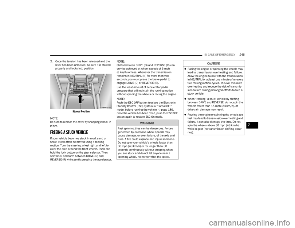
2. Once the tension has been released and the lever has been unlocked, be sure it is stowed
properly and locks into position.
Stowed Position
NOTE:Be sure to replace the cover by snapping it back in
place.
FREEING A STUCK VEHICLE
If your vehicle becomes stuck in mud, sand or
snow, it can often be moved using a rocking
motion. Turn the steering wheel right and left to
clear the area around the front wheels. Push and
hold the lock button on the gear selector. Then,
shift back and forth between DRIVE (D) and
REVERSE (R) while gently pressing the accelerator.
NOTE:Shifts between DRIVE (D) and REVERSE (R) can
only be achieved at wheel speeds of 5 mph
(8 km/h) or less. Whenever the transmission
remains in NEUTRAL (N) for more than two
seconds, you must press the brake pedal to
engage DRIVE (D) or REVERSE (R).
Use the least amount of accelerator pedal
pressure that will maintain the rocking motion
without spinning the wheels or racing the engine.
NOTE:Push the ESC OFF button to place the Electronic
Stability Control (ESC) system in “Partial OFF”
mode, before rocking the vehicle Ú page 180.
Once the vehicle has been freed, push the ESC OFF
button again to restore ESC On mode.
WARNING!
Fast spinning tires can be dangerous. Forces
generated by excessive wheel speeds may
cause damage, or even failure, of the axle and
tires. A tire could explode and injure someone.
Do not spin your vehicle's wheels faster than
30 mph (48 km/h) or for longer than 30
seconds continuously without stopping when
you are stuck and do not let anyone near a
spinning wheel, no matter what the speed.
CAUTION!
Racing the engine or spinning the wheels may
lead to transmission overheating and failure.
Allow the engine to idle with the transmission
in NEUTRAL for at least one minute after every
five rocking-motion cycles. This will minimize
overheating and reduce the risk of transmis -
sion failure during prolonged efforts to free a
stuck vehicle.
When “rocking” a stuck vehicle by shifting
between DRIVE and REVERSE, do not spin the
wheels faster than 15 mph (24 km/h), or
drivetrain damage may result.
Revving the engine or spinning the wheels too
fast may lead to transmission overheating and
failure. It can also damage the tires. Do not
spin the wheels above 30 mph (48 km/h)
while in gear (no transmission shifting occur -
ring).
7
23_WD_OM_EN_USC_t.book Page 245