tow DODGE DURANGO 2023 Manual Online
[x] Cancel search | Manufacturer: DODGE, Model Year: 2023, Model line: DURANGO, Model: DODGE DURANGO 2023Pages: 328, PDF Size: 13.82 MB
Page 264 of 328
262SERVICING AND MAINTENANCE
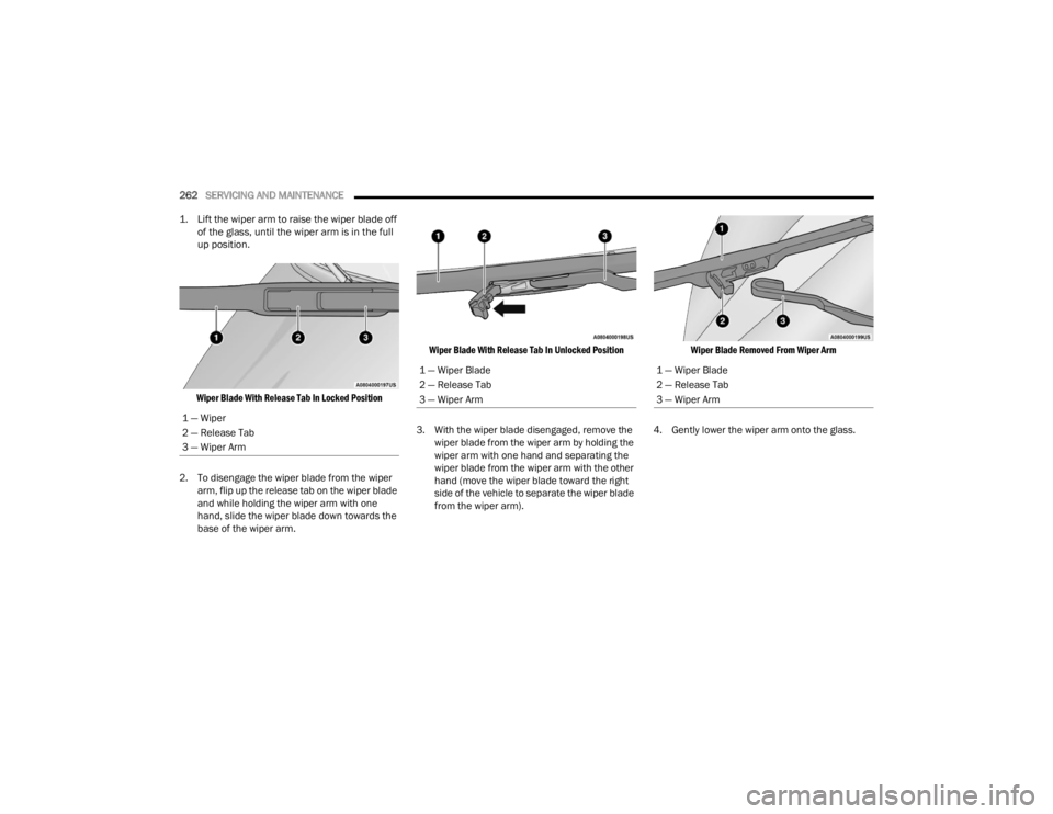
1. Lift the wiper arm to raise the wiper blade off of the glass, until the wiper arm is in the full
up position.
Wiper Blade With Release Tab In Locked Position
2. To disengage the wiper blade from the wiper arm, flip up the release tab on the wiper blade
and while holding the wiper arm with one
hand, slide the wiper blade down towards the
base of the wiper arm.
Wiper Blade With Release Tab In Unlocked Position
3. With the wiper blade disengaged, remove the wiper blade from the wiper arm by holding the
wiper arm with one hand and separating the
wiper blade from the wiper arm with the other
hand (move the wiper blade toward the right
side of the vehicle to separate the wiper blade
from the wiper arm).
Wiper Blade Removed From Wiper Arm
4. Gently lower the wiper arm onto the glass.
1 — Wiper
2 — Release Tab
3 — Wiper Arm
1 — Wiper Blade
2 — Release Tab
3 — Wiper Arm1 — Wiper Blade
2 — Release Tab
3 — Wiper Arm
23_WD_OM_EN_USC_t.book Page 262
Page 267 of 328
SERVICING AND MAINTENANCE265
Under normal operating conditions, the catalytic
converter will not require maintenance. However, it
is important to keep the engine properly tuned to
ensure proper catalyst operation and prevent
possible catalyst damage.
NOTE:Intentional tampering with emissions control
systems can result in civil penalties being
assessed against you.
In unusual situations involving grossly
malfunctioning engine operation, a scorching odor
may suggest severe and abnormal catalyst
overheating. If this occurs, stop the vehicle, turn off
the engine and allow it to cool. Service, including a
tune-up to the manufacturer's specifications,
should be obtained immediately.
To minimize the possibility of catalytic converter
damage:
Do not interrupt the ignition when the transmis -
sion is in gear and the vehicle is in motion.
Do not try to start the vehicle by pushing or
towing the vehicle.
Do not idle the engine with any ignition compo -
nents disconnected or removed, such as when
diagnostic testing, or for prolonged periods
during very rough idle or malfunctioning oper -
ating conditions.
COOLING SYSTEMCAUTION!
The catalytic converter requires the use of
unleaded fuel only. Leaded gasoline will
destroy the effectiveness of the catalyst as an
emissions control device and may seriously
reduce engine performance and cause
serious damage to the engine.
Damage to the catalytic converter can result if
your vehicle is not kept in proper operating
condition. In the event of engine malfunction,
particularly involving engine misfire or other
apparent loss of performance, have your
vehicle serviced promptly. Continued opera -
tion of your vehicle with a severe malfunction
could cause the converter to overheat,
resulting in possible damage to the converter
and vehicle.
WARNING!
You or others can be badly burned by hot
engine coolant (antifreeze) or steam from your
radiator. If you see or hear steam coming from
under the hood, do not open the hood until the
radiator has had time to cool. Never open a
cooling system pressure cap when the radi -
ator or coolant bottle is hot.
Keep hands, tools, clothing, and jewelry away
from the radiator cooling fan when the hood is
raised. The fan starts automatically and may
start at any time, whether the engine is
running or not.
When working near the radiator cooling fan,
disconnect the fan motor lead or turn the igni -
tion to the OFF mode. The fan is temperature
controlled and can start at any time the igni -
tion is in the ON mode.
8
23_WD_OM_EN_USC_t.book Page 265
Page 275 of 328
SERVICING AND MAINTENANCE273
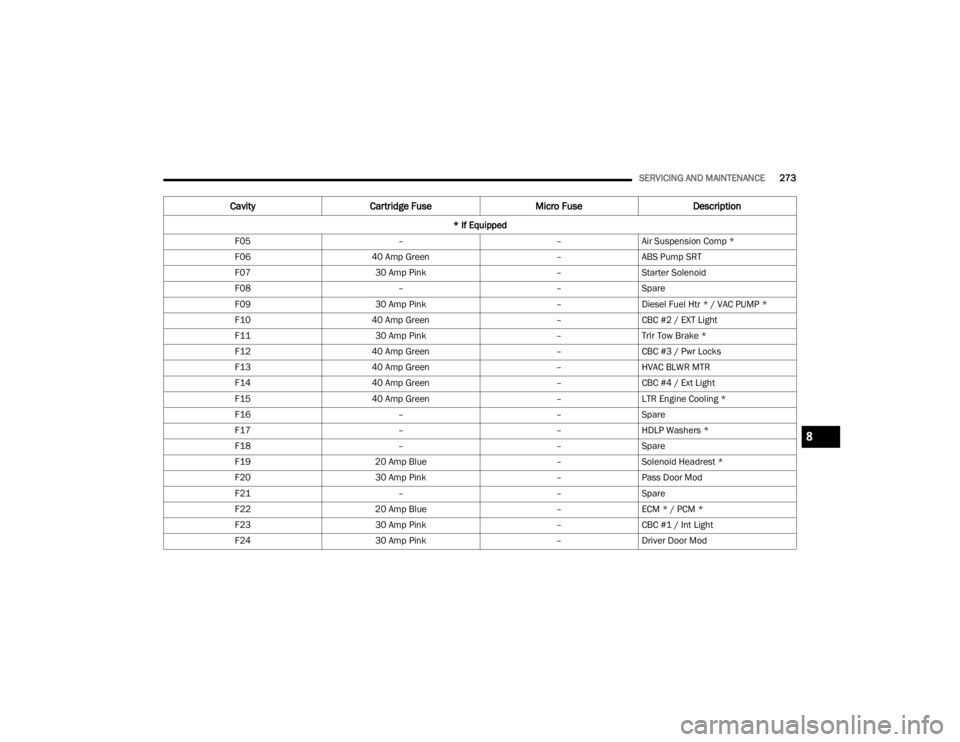
F05 ––Air Suspension Comp *
F06 40 Amp Green –ABS Pump SRT
F07 30 Amp Pink –Starter Solenoid
F08 ––Spare
F09 30 Amp Pink –Diesel Fuel Htr * / VAC PUMP *
F10 40 Amp Green –CBC #2 / EXT Light
F11 30 Amp Pink –Trlr Tow Brake *
F12 40 Amp Green –CBC #3 / Pwr Locks
F13 40 Amp Green –HVAC BLWR MTR
F14 40 Amp Green –CBC #4 / Ext Light
F15 40 Amp Green –LTR Engine Cooling *
F16 ––Spare
F17 ––HDLP Washers *
F18 ––Spare
F19 20 Amp Blue –Solenoid Headrest *
F20 30 Amp Pink –Pass Door Mod
F21 ––Spare
F22 20 Amp Blue –ECM * / PCM *
F23 30 Amp Pink –CBC #1 / Int Light
F24 30 Amp Pink –Driver Door Mod
Cavity Cartridge Fuse Micro FuseDescription
* If Equipped
8
23_WD_OM_EN_USC_t.book Page 273
Page 276 of 328
274SERVICING AND MAINTENANCE
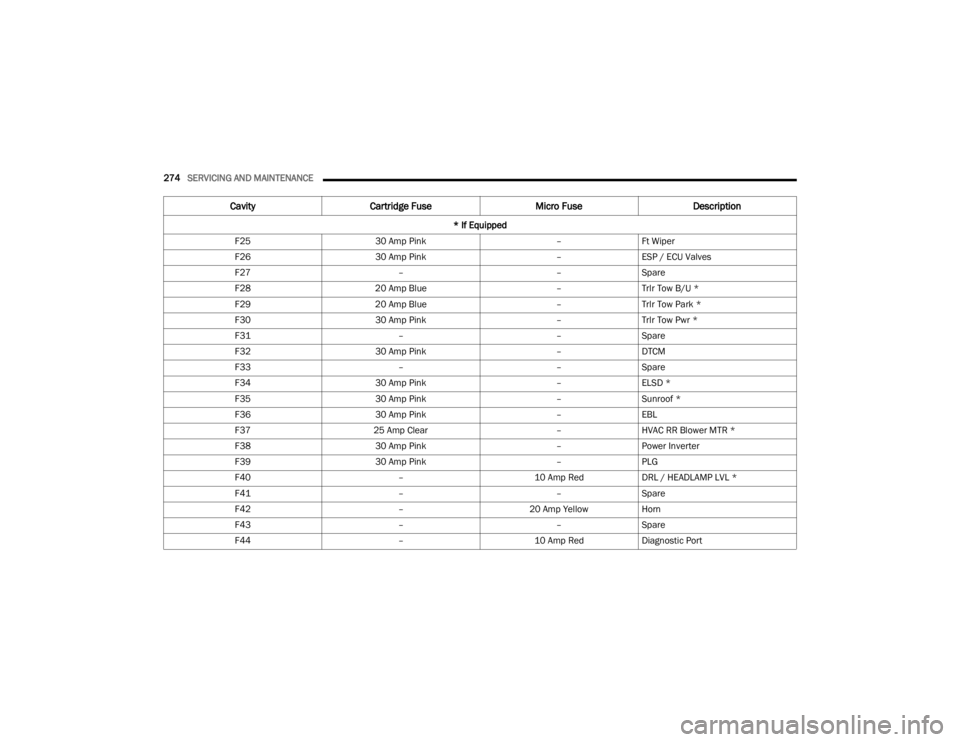
F25 30 Amp Pink –Ft Wiper
F26 30 Amp Pink –ESP / ECU Valves
F27 ––Spare
F28 20 Amp Blue –Trlr Tow B/U *
F29 20 Amp Blue –Trlr Tow Park *
F30 30 Amp Pink –Trlr Tow Pwr *
F31 ––Spare
F32 30 Amp Pink –DTCM
F33 ––Spare
F34 30 Amp Pink –ELSD *
F35 30 Amp Pink –Sunroof *
F36 30 Amp Pink –EBL
F37 25 Amp Clear –HVAC RR Blower MTR *
F38 30 Amp Pink –Power Inverter
F39 30 Amp Pink –PLG
F40 –10 Amp RedDRL / HEADLAMP LVL *
F41 ––Spare
F42 –20 Amp YellowHorn
F43 ––Spare
F44 –10 Amp RedDiagnostic Port
Cavity Cartridge Fuse Micro FuseDescription
* If Equipped
23_WD_OM_EN_USC_t.book Page 274
Page 277 of 328
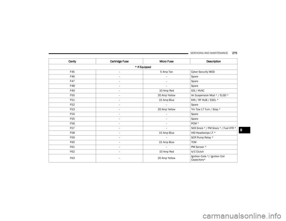
SERVICING AND MAINTENANCE275
F45 –5 Amp TanCyber Security MOD
F46 ––Spare
F47 ––Spare
F48 ––Spare
F49 –10 Amp RedICS / HVAC
F50 –20 Amp YellowAir Suspension Mod * / ELSD *
F51 –15 Amp BlueKIN / RF HUB / ESCL *
F52 ––Spare
F53 –20 Amp YellowTrlr Tow LT Turn / Stop *
F54 ––Spare
F55 ––Spare
F56 ––PCM *
F57 ––
NOX Snsrs * / PM Snsrs * / Fuel HTR *
F58 –15 Amp BlueHID Headlamps LT *
F59 ––SCR Pump Relay *
F60 –15 Amp BlueTCM
F61 ––PM Sensor *
F62 –10 Amp RedA/C Clutch
F63 –20 Amp YellowIgnition Coils */ Ignition Coil
Capacitors*
Cavity
Cartridge Fuse Micro FuseDescription
* If Equipped
8
23_WD_OM_EN_USC_t.book Page 275
Page 278 of 328
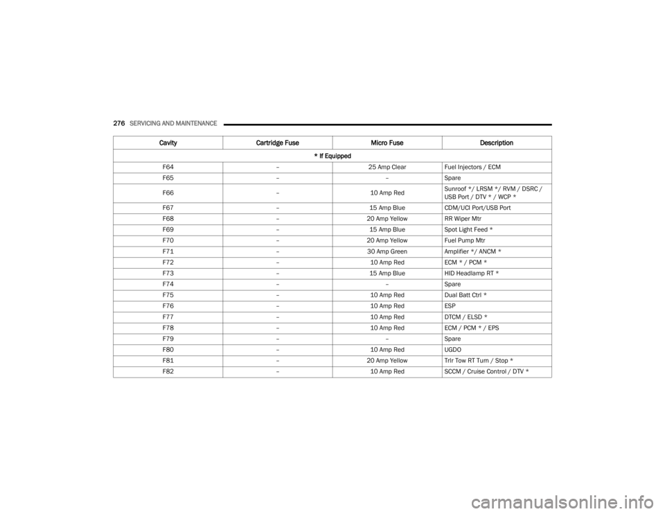
276SERVICING AND MAINTENANCE
F64 –25 Amp ClearFuel Injectors / ECM
F65 ––Spare
F66 –10 Amp RedSunroof */ LRSM */ RVM / DSRC /
USB Port / DTV * / WCP *
F67 –15 Amp BlueCDM/UCI Port/USB Port
F68 –20 Amp YellowRR Wiper Mtr
F69 –15 Amp BlueSpot Light Feed *
F70 –20 Amp YellowFuel Pump Mtr
F71 –30 Amp GreenAmplifier */ ANCM *
F72 –10 Amp RedECM * / PCM *
F73 –15 Amp BlueHID Headlamp RT *
F74 ––Spare
F75 –10 Amp RedDual Batt Ctrl *
F76 –10 Amp RedESP
F77 –10 Amp RedDTCM / ELSD *
F78 –10 Amp RedECM / PCM * / EPS
F79 ––Spare
F80 –10 Amp RedUGDO
F81 –20 Amp YellowTrlr Tow RT Turn / Stop *
F82 –10 Amp RedSCCM / Cruise Control / DTV *
Cavity Cartridge Fuse Micro FuseDescription
* If Equipped
23_WD_OM_EN_USC_t.book Page 276
Page 288 of 328
286SERVICING AND MAINTENANCE
Tire Loading And Tire Pressure
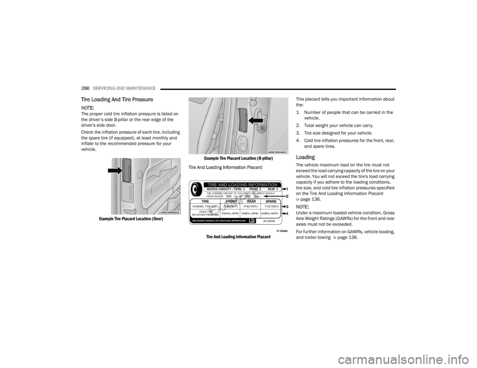
NOTE:The proper cold tire inflation pressure is listed on
the driver’s side B-pillar or the rear edge of the
driver's side door.
Check the inflation pressure of each tire, including
the spare tire (if equipped), at least monthly and
inflate to the recommended pressure for your
vehicle.
Example Tire Placard Location (Door) Example Tire Placard Location (B-pillar)
Tire And Loading Information Placard
Tire And Loading Information Placard
This placard tells you important information about
the:
1. Number of people that can be carried in the
vehicle.
2. Total weight your vehicle can carry.
3. Tire size designed for your vehicle.
4. Cold tire inflation pressures for the front, rear, and spare tires.
Loading
The vehicle maximum load on the tire must not
exceed the load carrying capacity of the tire on your
vehicle. You will not exceed the tire's load carrying
capacity if you adhere to the loading conditions,
tire size, and cold tire inflation pressures specified
on the Tire And Loading Information Placard
Úpage 136.
NOTE:Under a maximum loaded vehicle condition, Gross
Axle Weight Ratings (GAWRs) for the front and rear
axles must not be exceeded.
For further information on GAWRs, vehicle loading,
and trailer towing Ú page 136.
23_WD_OM_EN_USC_t.book Page 286
Page 289 of 328
SERVICING AND MAINTENANCE287
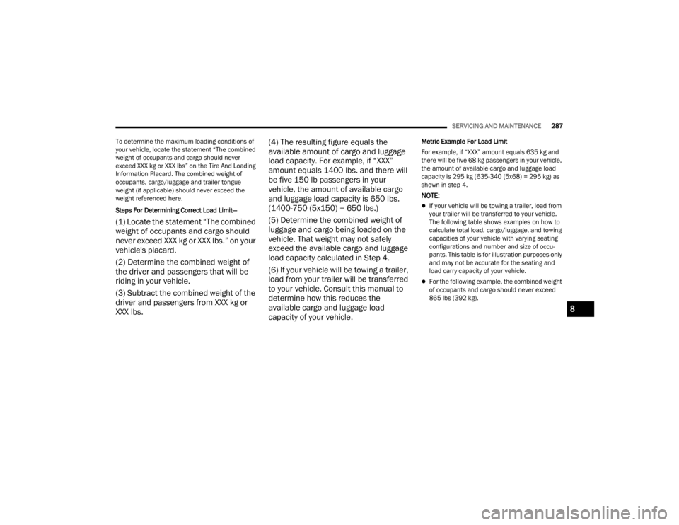
To determine the maximum loading conditions of
your vehicle, locate the statement “The combined
weight of occupants and cargo should never
exceed XXX kg or XXX lbs” on the Tire And Loading
Information Placard. The combined weight of
occupants, cargo/luggage and trailer tongue
weight (if applicable) should never exceed the
weight referenced here.
Steps For Determining Correct Load Limit—
(1) Locate the statement “The combined
weight of occupants and cargo should
never exceed XXX kg or XXX lbs.” on your
vehicle's placard.
(2) Determine the combined weight of
the driver and passengers that will be
riding in your vehicle.
(3) Subtract the combined weight of the
driver and passengers from XXX kg or
XXX lbs. (4) The resulting figure equals the
available amount of cargo and luggage
load capacity. For example, if “XXX”
amount equals 1400 lbs. and there will
be five 150 lb passengers in your
vehicle, the amount of available cargo
and luggage load capacity is 650 lbs.
(1400-750 (5x150) = 650 lbs.)
(5) Determine the combined weight of
luggage and cargo being loaded on the
vehicle. That weight may not safely
exceed the available cargo and luggage
load capacity calculated in Step 4.
(6) If your vehicle will be towing a trailer,
load from your trailer will be transferred
to your vehicle. Consult this manual to
determine how this reduces the
available cargo and luggage load
capacity of your vehicle.
Metric Example For Load Limit
For example, if “XXX” amount equals 635 kg and
there will be five 68 kg passengers in your vehicle,
the amount of available cargo and luggage load
capacity is 295 kg (635-340 (5x68) = 295 kg) as
shown in step 4.
NOTE:
If your vehicle will be towing a trailer, load from
your trailer will be transferred to your vehicle.
The following table shows examples on how to
calculate total load, cargo/luggage, and towing
capacities of your vehicle with varying seating
configurations and number and size of occu
-
pants. This table is for illustration purposes only
and may not be accurate for the seating and
load carry capacity of your vehicle.
For the following example, the combined weight
of occupants and cargo should never exceed
865 lbs (392 kg).
8
23_WD_OM_EN_USC_t.book Page 287
Page 293 of 328
SERVICING AND MAINTENANCE291
Run Flat Tires — If Equipped
Run Flat tires allow you the capability to drive
50 miles (80 km) at 50 mph (80 km/h) after a
rapid loss of inflation pressure. This rapid loss of
inflation is referred to as the Run Flat mode. A Run
Flat mode occurs when the tire inflation pressure is
of/or below 14 psi (96 kPa). Once a Run Flat tire
reaches the Run Flat mode it has limited driving
capabilities and needs to be replaced immediately.
A Run Flat tire is not repairable. When a Run Flat
tire is changed after being driven in a Run Flat
mode 14 psi (96 kPa) condition, please replace the
TPMS sensor as it is not designed to be reused.
NOTE:TPMS sensor must be replaced after driving the
vehicle on a flat tire condition.
It is not recommended driving a vehicle loaded at
full capacity or to tow a trailer while a tire is in the
Run Flat mode.
For more information Úpage 188.
Tire Spinning
When stuck in mud, sand, snow, or ice conditions,
do not spin your vehicle's wheels above 30 mph
(48 km/h) or for longer than 30 seconds
continuously without stopping.
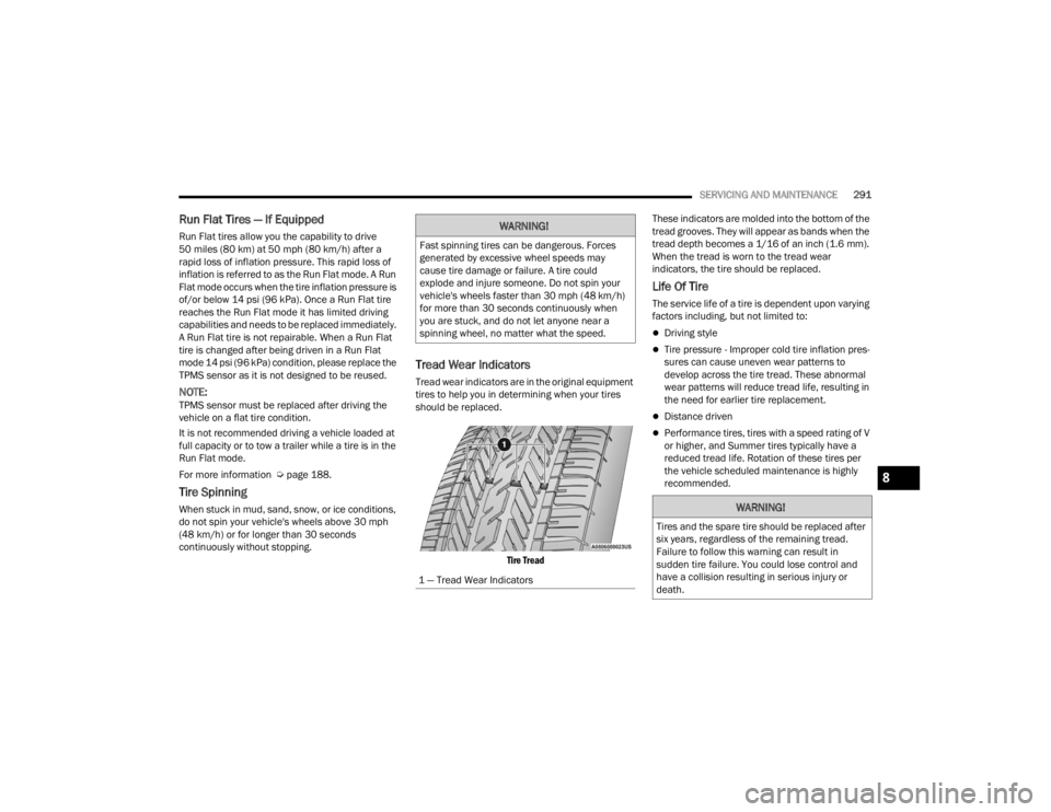
Tread Wear Indicators
Tread wear indicators are in the original equipment
tires to help you in determining when your tires
should be replaced.
Tire Tread
These indicators are molded into the bottom of the
tread grooves. They will appear as bands when the
tread depth becomes a 1/16 of an inch (1.6 mm).
When the tread is worn to the tread wear
indicators, the tire should be replaced.
Life Of Tire
The service life of a tire is dependent upon varying
factors including, but not limited to:
Driving style
Tire pressure - Improper cold tire inflation pres
-
sures can cause uneven wear patterns to
develop across the tire tread. These abnormal
wear patterns will reduce tread life, resulting in
the need for earlier tire replacement.
Distance driven
Performance tires, tires with a speed rating of V
or higher, and Summer tires typically have a
reduced tread life. Rotation of these tires per
the vehicle scheduled maintenance is highly
recommended.
WARNING!
Fast spinning tires can be dangerous. Forces
generated by excessive wheel speeds may
cause tire damage or failure. A tire could
explode and injure someone. Do not spin your
vehicle's wheels faster than 30 mph (48 km/h)
for more than 30 seconds continuously when
you are stuck, and do not let anyone near a
spinning wheel, no matter what the speed.
1 — Tread Wear Indicators
WARNING!
Tires and the spare tire should be replaced after
six years, regardless of the remaining tread.
Failure to follow this warning can result in
sudden tire failure. You could lose control and
have a collision resulting in serious injury or
death.
8
23_WD_OM_EN_USC_t.book Page 291
Page 295 of 328
SERVICING AND MAINTENANCE293
Summer tires do not contain the all season
designation or mountain/snowflake symbol on the
tire sidewall. Use Summer tires only in sets of four;
failure to do so may adversely affect the safety and
handling of your vehicle.
Snow Tires
Some areas of the country require the use of snow
tires during the Winter. Snow tires can be identified
by a “mountain/snowflake” symbol on the tire
sidewall. If you need snow tires, select tires
equivalent in size and type to the original
equipment tires. Use snow tires only in
sets of four; failure to do so may
adversely affect the safety and handling of your
vehicle.
Snow tires generally have lower speed ratings than
what was originally equipped with your vehicle and
should not be operated at sustained speeds over
75 mph (120 km/h). For speeds above 75 mph
(120 km/h) refer to original equipment or an authorized tire dealer for recommended safe
operating speeds, loading and cold tire inflation
pressures.
While studded tires improve performance on ice,
skid and traction capability on wet or dry surfaces
may be poorer than that of non-studded tires.
Some states prohibit studded tires; therefore, local
laws should be checked before using these tire
types.
SPARE TIRES — IF EQUIPPED
NOTE:For vehicles equipped with Tire Service Kit instead
of a spare tire, please refer to “Tire Service Kit” in
“In Case Of Emergency” for further information.
For restrictions when towing with a spare tire
designated for temporary emergency use
Ú
page 142.
Spare Tire Matching Original Equipped Tire
And Wheel — If Equipped
Your vehicle may be equipped with a spare tire and
wheel equivalent in look and function to the
original equipment tire and wheel found on the
front or rear axle of your vehicle. This spare tire
may be used in the tire rotation for your vehicle. If
your vehicle has this option, refer to an authorized
tire dealer for the recommended tire rotation
pattern.
Compact Spare Tire — If Equipped
The compact spare is for temporary emergency
use only. You can identify if your vehicle is
equipped with a compact spare by looking at the
spare tire description on the Tire And Loading
Information Placard located on the driver’s side
door opening or on the sidewall of the tire.
Compact spare tire descriptions begin with the
letter “T” or “S” preceding the size designation.
Example: T145/80D18 103M.
T, S = Temporary Spare Tire
Since this tire has limited tread life, the original
equipment tire should be repaired (or replaced)
and reinstalled on your vehicle at the first
opportunity.
WARNING!
Do not use Summer tires in snow/ice conditions.
You could lose vehicle control, resulting in
severe injury or death. Driving too fast for
conditions also creates the possibility of loss of
vehicle control.
CAUTION!
Because of the reduced ground clearance, do
not take your vehicle through an automatic car
wash with a compact or limited use temporary
spare installed. Damage to the vehicle may
result.
8
23_WD_OM_EN_USC_t.book Page 293