remote start DODGE DURANGO SRT 2019 User Guide
[x] Cancel search | Manufacturer: DODGE, Model Year: 2019, Model line: DURANGO SRT, Model: DODGE DURANGO SRT 2019Pages: 572, PDF Size: 6.59 MB
Page 61 of 572
The front ventilated seats control buttons are located
within the Uconnect system. You can gain access to the
control buttons through the climate screen or the controls
screen.
•Press the ventilated seat button
once to choose HI.
•Press the ventilated seat buttona second time to
choose LO.
• Press the ventilated seat buttona third time to turn
the ventilated seat off.
NOTE: The engine must be running for the ventilated seats
to operate.
Vehicles Equipped With Remote Start
On models that are equipped with remote start, the venti-
lated seats can be programmed to come on during a remote
start.
This feature can be programmed through the Uconnect
system. Refer to “Uconnect Settings” in “Multimedia” for
further information.
HEAD RESTRAINTS
Head restraints are designed to reduce the risk of injury by
restricting head movement in the event of a rear impact.
Head restraints should be adjusted so that the top of the
head restraint is located above the top of your ear.
WARNING!
• All occupants, including the driver, should not oper-
ate a vehicle or sit in a vehicle’s seat until the head
restraints are placed in their proper positions in
order to minimize the risk of neck injury in the event
of a crash.
• Head restraints should never be adjusted while the
vehicle is in motion. Driving a vehicle with the head
restraints improperly adjusted or removed could
cause serious injury or death in the event of a
collision.
3
GETTING TO KNOW YOUR VEHICLE 59
Page 68 of 572
The heated steering wheel control button is located on the
center of the instrument panel below the touchscreen and
within the climate or controls screen of the touchscreen.
•Push the heated steering wheel button
once to turn
the heating element on.
• Push the heated steering wheel buttona second time
to turn the heating element off.
NOTE: The engine must be running for the heated steering
wheel to operate.
Vehicles Equipped With Remote Start
On models that are equipped with remote start, the heated
steering wheel can be programmed to come on during a
remote start.
This feature can be programmed through the Uconnect
system. Refer to “Uconnect Settings” in “Multimedia” for
further information.
WARNING!
• Persons who are unable to feel pain to the skin
because of advanced age, chronic illness, diabetes,
(Continued)
WARNING! (Continued)
spinal cord injury, medication, alcohol use, exhaus-
tion, or other physical conditions must exercise care
when using the steering wheel heater. It may cause
burns even at low temperatures, especially if used
for long periods.
• Do not place anything on the steering wheel that
insulates against heat, such as a blanket or steering
wheel covers of any type and material. This may
cause the steering wheel heater to overheat.
MIRRORS
Automatic Dimming Mirror
The mirror head can be adjusted up, down, left, and right
for various drivers. The mirror should be adjusted to center
on the view through the rear window.
This mirror automatically adjusts for headlight glare from
vehicles behind you.
NOTE: The Automatic Dimming Mirror feature is disabled
when the vehicle is in REVERSE to improve rear view
viewing.
66 GETTING TO KNOW YOUR VEHICLE
Page 83 of 572
Rain Sensing Wipers — If Equipped
This feature senses rain or snowfall on the windshield and
automatically activates the wipers for the driver. The
feature is especially useful for road splash or overspray
from the windshield washers of the vehicle ahead. Rotate
the end of the multifunction lever to one of four settings to
activate this feature.
The sensitivity of the system can be adjusted with the
multifunction lever. Wiper delay position one is the least
sensitive, and wiper delay position four is the most sensi-
tive.
NOTE:Wiper delay position three should be used for
normal rain conditions.
Settings one and two can be used if the driver desires less
wiper sensitivity. Setting four can be used if the driver
desires more sensitivity. Place the wiper switch in the OFF
position when not using the system.
NOTE:
• The Rain Sensing feature will not operate when the
wiper switch is in the low or high-speed position.
•
The Rain Sensing feature may not function properly when
ice, or dried salt water is present on the windshield.
• Use of Rain-X or products containing wax or silicone
may reduce Rain Sensing performance.
• The Rain Sensing feature can be turned on and off using
the Uconnect System, refer to “Uconnect Settings” in
“Multimedia” for further information.
The Rain Sensing system has protection features for the
wiper blades and arms, and will not operate under the
following conditions:
• Low Ambient Temperature — When the ignition is first
turned ON, the Rain Sensing system will not operate
until the wiper switch is moved, vehicle speed is greater
than 3 mph (5 km/h), or the outside temperature is
greater than 32°F (0°C).
• Transmission In NEUTRAL Position — When the igni-
tion is ON, and the automatic transmission is in the
NEUTRAL position, the Rain Sensing system will not
operate until the wiper switch is moved, vehicle speed is
greater than 3 mph (5 km/h), or the gear selector is
moved out of the NEUTRAL position.
Remote Start Mode Inhibit — On vehicles equipped with
Remote Starting system, Rain Sensing wipers are not
operational when the vehicle is in the remote start mode.
Once the operator is in the vehicle and has placed the
3
GETTING TO KNOW YOUR VEHICLE 81
Page 144 of 572
•Reconfigurable Telltales/Information
• Gear Selector Status (PRND)
• Driver Interactive Display (Compass, Temp, Range to
Empty, Trip A, Trip B, Average Fuel Economy, Current
Fuel Economy, Time, Trailer Trip and Gain)
The instrument cluster display will normally display the
main menu or the screens of a selected feature of the main
menu. The main display area also displays “pop up”
messages that consist of approximately 60 possible warn-
ing or information messages. These pop up messages fall
into several categories:
• Five Second Stored Messages
When the appropriate conditions occur, this type of mes-
sage takes control of the main display area for five seconds
and then returns to the previous screen. Most of the
messages of this type are then stored (as long as the
condition that activated it remains active) and can be
reviewed from the “Messages” main menu item. Examples
of this message type are “Right Front Turn Signal Lamp
Out” and “Low Tire Pressure.” •
Unstored Messages
This message type is displayed indefinitely or until the
condition that activated the message is cleared. Examples
of this message type are “Turn Signal On” (if a turn signal
is left on) and “Lights On” (if driver leaves the vehicle).
• Unstored Messages Until RUN
These messages deal primarily with the Remote Start
feature. This message type is displayed until the ignition is
in the RUN state. Examples of this message type are
“Remote Start Canceled - Door Ajar” and “Press Brake
Pedal and Push Button to Start.”
• Five Second Unstored Messages
When the appropriate conditions occur, this type of mes-
sage takes control of the main display area for five seconds
and then returns to the previous screen. An example of this
message type is “Automatic High Beams On.”
142 GETTING TO KNOW YOUR INSTRUMENT PANEL
Page 146 of 572
3. Without pushing the brake pedal, push the ENGINESTART/STOP button once to return the ignition to the
OFF/LOCK position.
NOTE: If the indicator message illuminates when you start
the vehicle, the oil change indicator system did not reset. If
necessary, repeat this procedure.
Display And Messages
Includes the following, but not limited to:
• Front Seatbelts Unbuckled
• Driver Seat Belt Unbuckled
• Passenger Seat Belt Unbuckled
• Traction Control Off
• Washer Fluid Low
• Oil Pressure Low
• Oil Change Due
• Fuel Low
• Service Anti-lock Brake System
• Service Electronic Throttle Control
• Service Power Steering •
Cruise Off
• Cruise Ready
• ACC Override
• Cruise Set To XXX MPH or km/h
• Tire Pressure Screen With Low Tire(s)
• Service Tire Pressure System
• Park Brake Engaged
• Brake Fluid Low
• Engine Temperature Hot
• Lights On
• Right Front Turn Signal Light Out
• Right Rear Turn Signal Light Out
• Left Front Turn Signal Light Out
• Left Rear Turn Signal Light Out
• Ignition or Accessory On
• Vehicle Not In Park
• Remote Start Active Push Start Button
• Remote Start Canceled Fuel Low
144 GETTING TO KNOW YOUR INSTRUMENT PANEL
Page 147 of 572
•Remote Start Canceled Too Cold
• Remote Start Canceled Door Open
• Remote Start Canceled Hood Open
• Remote Start Canceled Liftgate Open
• Remote Start Canceled Time Expired
• Remote Start Disabled Start To Reset
• Service Air Bag System
• Service Air Bag Warning Light
• Door Open
• Doors Open
• Liftgate Open
• Hood Open
• Shift Not Allowed
• Vehicle Speed Too High To Shift to D
• Vehicle Speed is Too High to Shift to R
• Vehicle Speed is Too High to Shift to P
• Service Transmission
• Service Shifter The Reconfigurable Telltales section is divided into the
white or yellow telltales area on the left, and the green or
red telltales area on the right.
Instrument Cluster Display Menu Items
The instrument cluster display can be used to view the
main menu items for several features. Use the
upand
down arrow buttons to scroll through the driver interactive
display menu options until the desired menu is reached.
NOTE: Depending on the vehicle’s options, feature set-
tings may vary.
Speedometer
Push and release the upordown arrow button until the
main gauge icon is displayed in the instrument cluster
display. Push and release the leftorright arrow button to
select the large or small speedometer display. Push and
release the OKbutton to toggle units (km/h or mph) of the
speedometer.
Vehicle Info
Push and release the upordown arrow button until the
Vehicle Info icon/title is highlighted in the instrument
cluster display. Push the leftorright arrow button to scroll
through the information submenus.
4
GETTING TO KNOW YOUR INSTRUMENT PANEL 145
Page 261 of 572

CAUTION!(Continued)
•Shift into or out of REVERSE only after the vehicle
has come to a complete stop and the engine is at idle
speed.
• Before shifting into any gear, make sure your foot is
firmly on the brake pedal.
Keyless Enter-N-Go — Ignition
This feature allows the driver to operate the ignition switch
with the push of a button, as long as the Remote Start/
Keyless Enter-N-Go key fob is in the passenger
compartment.
Normal Starting
To Turn On The Engine Using The ENGINE START/
STOP Button
1. The transmission must be in PARK.
2. Press and hold the brake pedal while pushing the ENGINE START/STOP button once.
3. The system takes over and attempts to start the vehicle. If the vehicle fails to start, the starter will disengage
automatically after 10 seconds.
4. If you wish to stop the cranking of the engine prior to the engine starting, push the button again.
NOTE: Normal starting of either a cold or a warm engine
is obtained without pumping or pressing the accelerator
pedal.
Keyless Push Button Ignition
6
STARTING AND OPERATING 259
Page 384 of 572
5. After 25 miles (40 km), check the lug nut torque with atorque wrench to ensure that all lug nuts are properly
seated against the wheel.
JUMP STARTING
If your vehicle has a discharged battery, it can be jump
started using a set of jumper cables and a battery in another
vehicle, or by using a portable battery booster pack. Jump
starting can be dangerous if done improperly, so please
follow the procedures in this section carefully.
WARNING!
Do not attempt jump starting if the battery is frozen. It
could rupture or explode and cause personal injury.
CAUTION!
Do not use a portable battery booster pack or any other
booster source with a system voltage greater than 12
Volts or damage to the battery, starter motor, alternator
or electrical system may occur.
NOTE: When using a portable battery booster pack, follow
the manufacturer’s operating instructions and precautions.
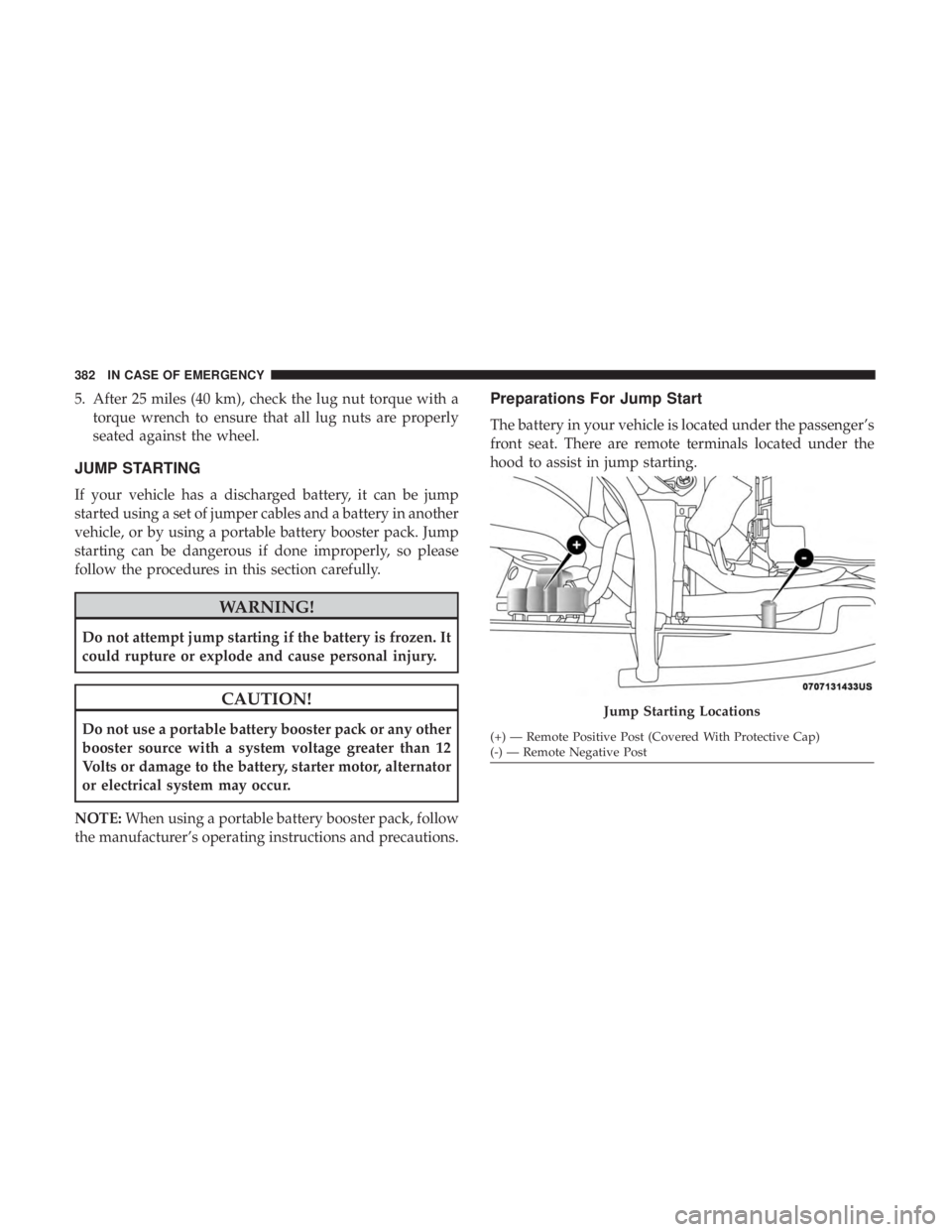
Preparations For Jump Start
The battery in your vehicle is located under the passenger’s
front seat. There are remote terminals located under the
hood to assist in jump starting.
Jump Starting Locations
(+) — Remote Positive Post (Covered With Protective Cap)
(-) — Remote Negative Post
382 IN CASE OF EMERGENCY
Page 385 of 572
WARNING!
•Take care to avoid the radiator cooling fan whenever
the hood is raised. It can start anytime the ignition
switch is ON. You can be injured by moving fan
blades.
• Remove any metal jewelry such as rings, watch
bands and bracelets that could make an inadvertent
electrical contact. You could be seriously injured.
• Batteries contain sulfuric acid that can burn your
skin or eyes and generate hydrogen gas which is
flammable and explosive. Keep open flames or
sparks away from the battery.
NOTE: Be sure that the disconnected cable ends do not
touch each other, or either vehicle, until properly con-
nected for jump starting.
1. Apply the parking brake, shift the automatic transmis- sion into PARK and turn the ignition OFF.
2. Turn off the heater, radio, and all unnecessary electrical accessories.
3. Remove the protective cover over the remote positive (+) battery post. Pull upward on the cover to remove it. 4. If using another vehicle to jump start the battery, park
the vehicle within the jumper cables reach, apply the
parking brake and make sure the ignition is OFF.
WARNING!
Do not allow vehicles to touch each other as this could
establish a ground connection and personal injury
could result.
Jump Starting Procedure
WARNING!
Failure to follow this jump starting procedure could
result in personal injury or property damage due to
battery explosion.
CAUTION!
Failure to follow these procedures could result in
damage to the charging system of the booster vehicle
or the discharged vehicle.
NOTE: Make sure at all times that unused ends of jumper
cables are not contacting each other or either vehicle while
making connections.
7
IN CASE OF EMERGENCY 383
Page 386 of 572
Connecting The Jumper Cables
1. Connect the positive(+)end of the jumper cable to the
remote positive (+)post of the discharged vehicle.
2. Connect the opposite end of the positive (+)jumper
cable to the positive (+)post of the booster battery.
3. Connect the negative end (-)of the jumper cable to the
negative (-)post of the booster battery.
4. Connect the opposite end of the negative (-)jumper
cable to the remote negative (-)post of the vehicle with
the discharged battery.
WARNING!
Do not connect the jumper cable to the negative (-) post
of the discharged battery. The resulting electrical spark
could cause the battery to explode and could result in
personal injury. Only use the specific ground point, do
not use any other exposed metal parts.
5. Start the engine in the vehicle that has the booster battery, let the engine idle a few minutes, and then start
the engine in the vehicle with the discharged battery.
CAUTION!
Do not run the booster vehicle engine above 2,000 rpm
since it provides no charging benefit, wastes fuel, and
can damage booster vehicle engine.
6. Once the engine is started, remove the jumper cables in the reverse sequence:
Disconnecting The Jumper Cables
1. Disconnect the negative (-)end of the jumper cable from
the remote negative (-)post of the discharged vehicle.
2. Disconnect the opposite end of the negative (-)jumper
cable from the negative (-)post of the booster battery.
3. Disconnect the positive (+)end of the jumper cable from
the positive (+)post of the booster battery.
4. Disconnect the opposite end of the positive (+)jumper
cable from the remote positive (+)post of the discharged
vehicle.
5. Reinstall the protective cover over the remote positive (+) post of the discharged vehicle.
384 IN CASE OF EMERGENCY