DODGE GRAND CARAVAN 2011 5.G Workshop Manual
Manufacturer: DODGE, Model Year: 2011, Model line: GRAND CARAVAN, Model: DODGE GRAND CARAVAN 2011 5.GPages: 100, PDF Size: 4.02 MB
Page 51 of 100
PROGRAMMABLE FEATURES
Electronic Vehicle Information Center (EVIC) – If Equipped
• The EVIC can be used to program the following Personal Settings. Press andrelease the MENU button until Personal Settings displays, then press the DOWN
button
to scroll through the settings. Press the SELECT buttonto
change the setting.
• Language • Turn Headlamps On With Remote Key
Unlock
• Lock Door Automatically at 15 mph (24 km/h) • Confirmation of Voice Commands
• Auto Unlock On Exit • Illuminated Approach
• Remote Unlock Driver's Door 1st • Hill Start Assist (HSA)
• Sound Horn With Remote Key Lock • Display Units In
• Flash Lights With Remote Key Lock • Automatic Compass Calibration
• Delay Turning Headlights Off • Compass Variance
• Delay Power Off to Accessories until Exit • To Set the Variance
Key Fob Programmable Features
• The following features may also be programmed by using the Key Fob transmitter
or the ignition switch and driver's door lock switch.
NOTE: Pressing the LOCK button while you are inside the vehicle will activate the
Vehicle Security Alarm. Opening a door with the Vehicle Security Alarm activated will
cause the alarm to sound. Press the UNLOCK button to deactivate the Vehicle Security
Alarm.
Unlock On First Press• To unlock either the driver's side, or all doors, on the first press of the UNLOCK button:
• Press and hold the LOCK button for at least 4 seconds, but no longer than
10 seconds. Then, press and hold the UNLOCK button while still holding the
LOCK button.
• Release both buttons at the same time.
ELECTRONICS
49
Page 52 of 100
Auto Unlock Doors On Exit• To have all of the vehicle doors unlock when any door is opened: • Enter your vehicle and close all the doors.
• Cycle the ignition switch between LOCK and ON and then back to LOCK fourtimes, ending up in the LOCK position (do not start the engine).
• Press the power door UNLOCK switch to unlock the doors. A single chime will indicate that programming is complete.
Auto Door Lock • To have the doors lock automatically when the vehicle’s speed exceeds 15 mph (24 km/h):
• Enter your vehicle and close all the doors.
• Cycle the ignition switch between LOCK and ON and then back to LOCK four
times, ending up in the LOCK position (do not start the engine).
• Press the power door LOCK switch to lock the doors. A single chime will indicate that programming is complete.
Sound Horn With Lock • To turn the horn chirp on or off when the doors are locked: • Press the LOCK button for at least 4 seconds, but no longer than 10 seconds.Then, press the PANIC button while still holding the LOCK button.
• Release both buttons at the same time.
Flashing Lights With Lock • The turn signal lights flashing, when the doors are locked or unlocked, feature can be turned on or off. To turn this feature on or off:
• Press and hold the UNLOCK button for at least 4 seconds, but no longer than
10 seconds. Then, press and hold the LOCK button while still holding the
UNLOCK button.
• Release both buttons at the same time.
ELECTRONICS
50
Page 53 of 100
UNIVERSAL GARAGE DOOR OPENER
(HomeLink®)
Programming HomeLink®
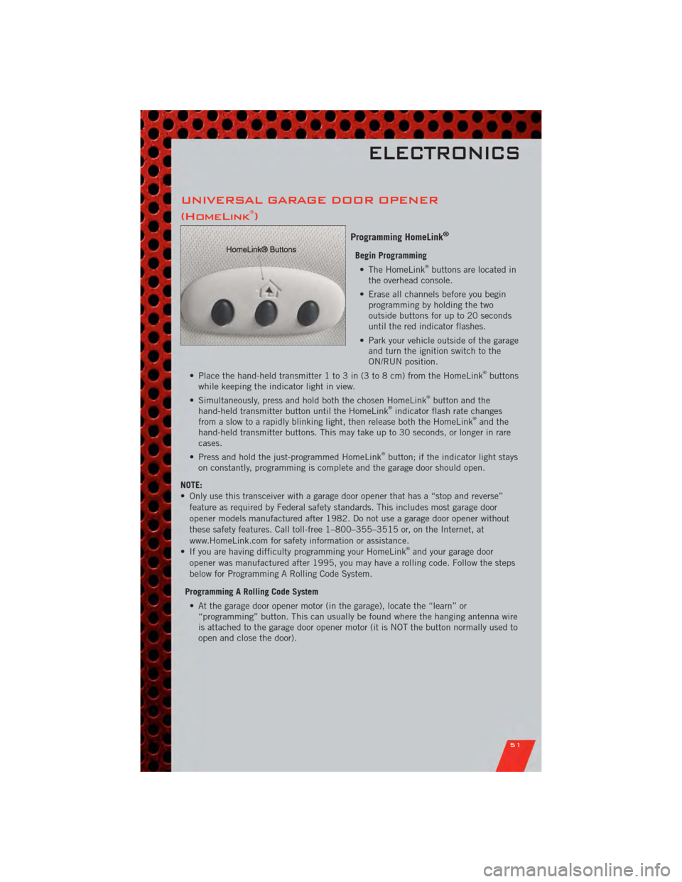
Begin Programming• The HomeLink®buttons are located in
the overhead console.
• Erase all channels before you begin programming by holding the two
outside buttons for up to 20 seconds
until the red indicator flashes.
• Park your vehicle outside of the garage and turn the ignition switch to the
ON/RUN position.
• Place the hand-held transmitter 1 to 3 in (3 to 8 cm) from the HomeLink
®buttons
while keeping the indicator light in view.
• Simultaneously, press and hold both the chosen HomeLink
®button and the
hand-held transmitter button until the HomeLink®indicator flash rate changes
from a slow to a rapidly blinking light, then release both the HomeLink®and the
hand-held transmitter buttons. This may take up to 30 seconds, or longer in rare
cases.
• Press and hold the just-programmed HomeLink
®button; if the indicator light stays
on constantly, programming is complete and the garage door should open.
NOTE:
• Only use this transceiver with a garage door opener that has a “stop and reverse” feature as required by Federal safety standards. This includes most garage door
opener models manufactured after 1982. Do not use a garage door opener without
these safety features. Call toll-free 1–800–355–3515 or, on the Internet, at
www.HomeLink.com for safety information or assistance.
• If you are having difficulty programming your HomeLink
®and your garage door
opener was manufactured after 1995, you may have a rolling code. Follow the steps
below for Programming A Rolling Code System.
Programming A Rolling Code System • At the garage door opener motor (in the garage), locate the “learn” or “programming” button. This can usually be found where the hanging antenna wire
is attached to the garage door opener motor (it is NOT the button normally used to
open and close the door).
ELECTRONICS
51
Page 54 of 100
• Firmly press and release the “learn” or “programming” button. The name and colorof the button may vary by manufacturer. Within 30 seconds, return to the vehicle
and press the programmed HomeLink
®button twice (holding the button for two
seconds each time). If the device is plugged in and activates, programming is
complete.
• If the device does not activate, press the button a third time (for two seconds) to complete the programming.
Using HomeLink
®
• To operate, simply press and release the programmed HomeLink®button and the
programmed device will operate.
• Refer to your Owner’s Manual on the DVD for further details. If you have any problems programming HomeLink
®, or require assistance, please call toll-free
1–800–355–3515 or, on the Internet, at www.HomeLink.com.
WARNING!
• Your motorized door or gate will open and close while you are programming the universal transceiver. Do not program the transceiver if people or pets are
in the path of the door or gate.
• Do not run your vehicle in a closed garage or confined area while programming the transceiver. Exhaust gas from your vehicle contains Carbon
Monoxide (CO) which is odorless and colorless. Carbon Monoxide is
poisonous when inhaled and can cause you and others to be severely injured
or killed.
ELECTRONICS
52
Page 55 of 100
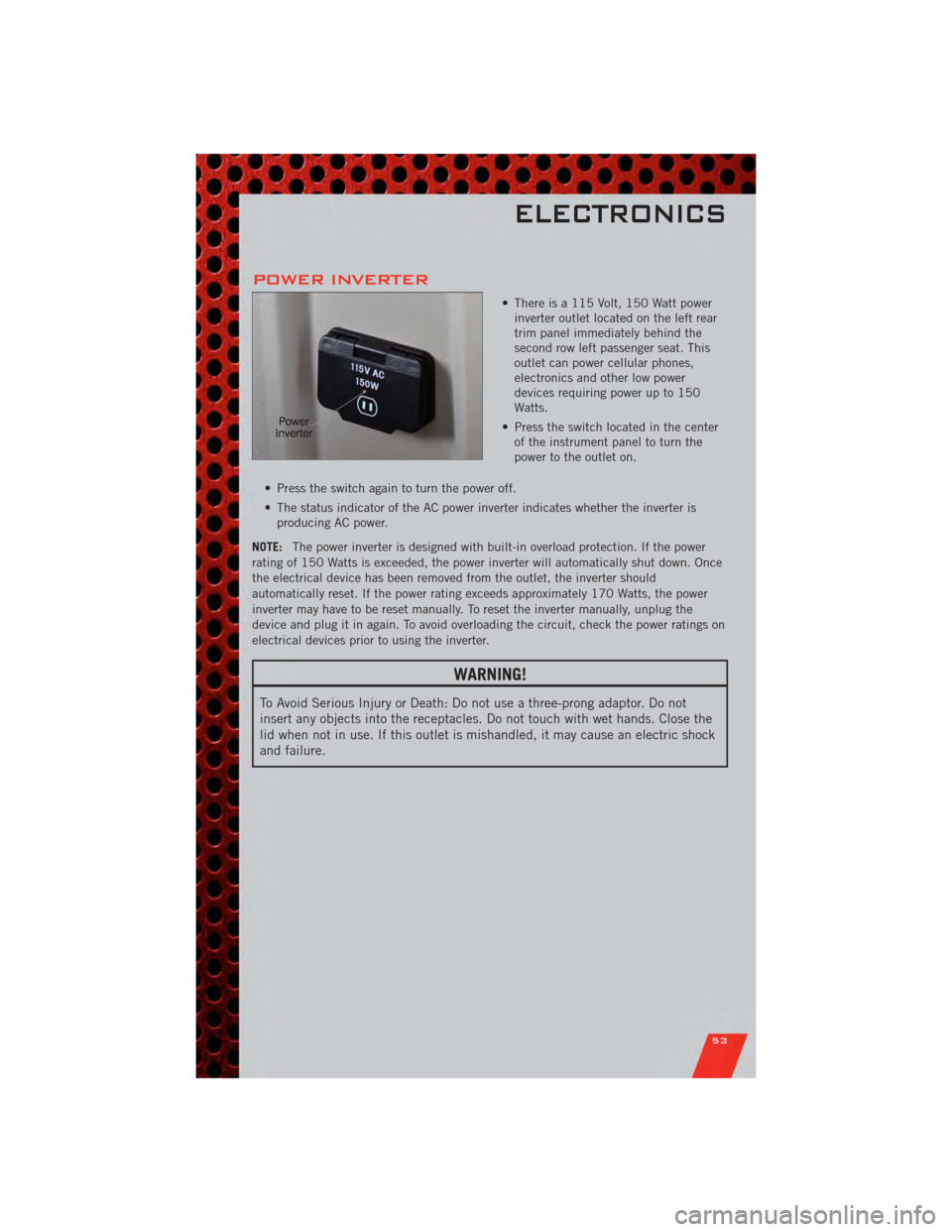
POWER INVERTER
• There is a 115 Volt, 150 Watt powerinverter outlet located on the left rear
trim panel immediately behind the
second row left passenger seat. This
outlet can power cellular phones,
electronics and other low power
devices requiring power up to 150
Watts.
• Press the switch located in the center of the instrument panel to turn the
power to the outlet on.
• Press the switch again to turn the power off.
• The status indicator of the AC power inverter indicates whether the inverter is producing AC power.
NOTE: The power inverter is designed with built-in overload protection. If the power
rating of 150 Watts is exceeded, the power inverter will automatically shut down. Once
the electrical device has been removed from the outlet, the inverter should
automatically reset. If the power rating exceeds approximately 170 Watts, the power
inverter may have to be reset manually. To reset the inverter manually, unplug the
device and plug it in again. To avoid overloading the circuit, check the power ratings on
electrical devices prior to using the inverter.
WARNING!
To Avoid Serious Injury or Death: Do not use a three-prong adaptor. Do not
insert any objects into the receptacles. Do not touch with wet hands. Close the
lid when not in use. If this outlet is mishandled, it may cause an electric shock
and failure.
ELECTRONICS
53
Page 56 of 100
POWER OUTLETS
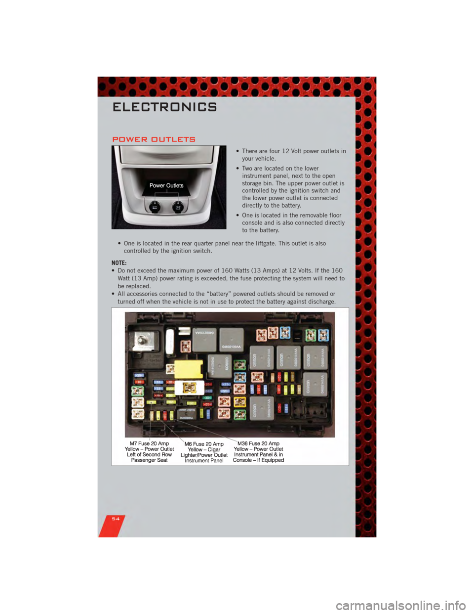
• There are four 12 Volt power outlets inyour vehicle.
• Two are located on the lower instrument panel, next to the open
storage bin. The upper power outlet is
controlled by the ignition switch and
the lower power outlet is connected
directly to the battery.
• One is located in the removable floor console and is also connected directly
to the battery.
• One is located in the rear quarter panel near the liftgate. This outlet is also controlled by the ignition switch.
NOTE:
• Do not exceed the maximum power of 160 Watts (13 Amps) at 12 Volts. If the 160 Watt (13 Amp) power rating is exceeded, the fuse protecting the system will need to
be replaced.
• All accessories connected to the “battery” powered outlets should be removed or turned off when the vehicle is not in use to protect the battery against discharge.
ELECTRONICS
54
Page 57 of 100
IN-FLOOR STORAGE –
STOW 'N GO®
Second Row Seat Storage Bins
• Storage bins are located in the floorin front of the second row seats that
can be used when the second row
seat is in the upright position. Pull
up on the storage bin latch to open
the cover. Slide the storage bin
locking mechanism to the "Lock"
position to allow greater access to
the storage bin.
Cargo Area Storage
• The liftgate sill plate has a raisedline with the statement “Load To
This Line”. This line indicates how
far rearward cargo can be placed
without interfering with liftgate
closing.
WARNING!
In a collision, serious injury could
result if the seat storage bin covers
are not properly latched. Do not
drive the vehicle with the storage bin
covers open. Keep the storage bin
covers closed and latched while the
vehicle is in motion. Do not use a
storage bin latch as a tie down.
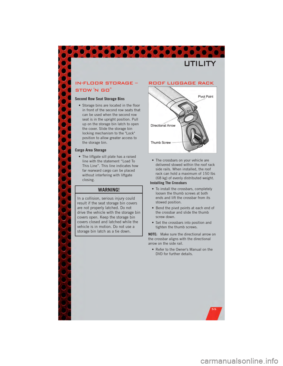
ROOF LUGGAGE RACK
• The crossbars on your vehicle aredelivered stowed within the roof rack
side rails. When installed, the roof
rack can hold a maximum of 150 lbs
(68 kg) of evenly distributed weight.
Installing The Crossbars
• To install the crossbars, completely loosen the thumb screws at both
ends and lift the crossbar from its
stowed position.
• Bend the pivot points at each end of the crossbar and slide the thumb
screw down.
• Set the crossbars into position and tighten the thumb screws.
NOTE: Make sure the directional arrow on
the crossbar aligns with the directional
arrow on the side rail.
• Refer to the Owner's Manual on theDVD for further details.
UTILITY
55
Page 58 of 100
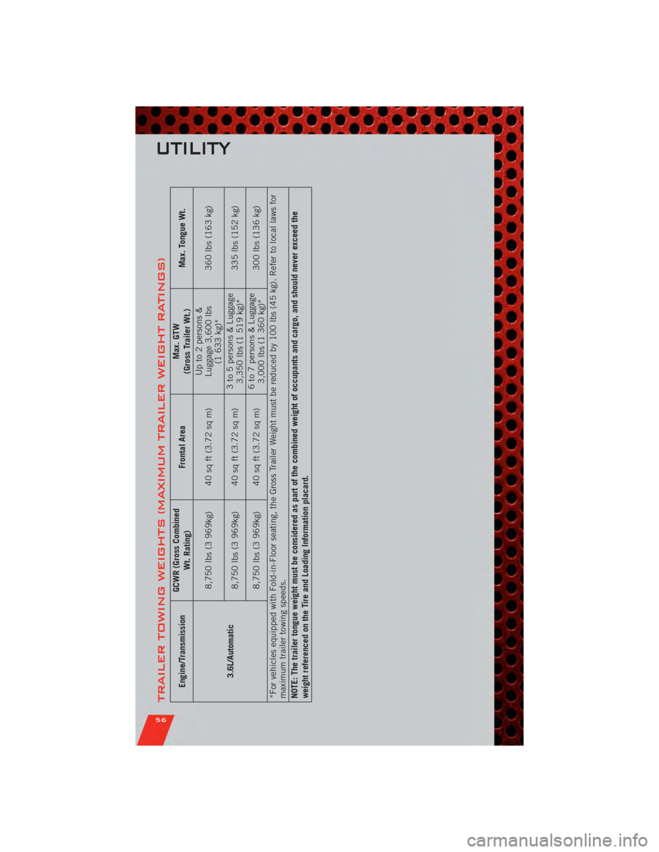
TRAILER TOWING WEIGHTS (MAXIMUM TRAILER WEIGHT RATINGS)
Engine/TransmissionGCWR (Gross Combined
Wt. Rating) Frontal Area Max. GTW
(Gross Trailer Wt.) Max. Tongue Wt.
3.6L/Automatic 8,750 lbs (3 969kg) 40 sq ft (3.72 sq m)
Up to 2 persons &
Luggage 3,600 lbs (1 633 kg)* 360 lbs (163 kg)
8,750 lbs (3 969kg) 40 sq ft (3.72 sq m) 3 to 5 persons & Luggage
3,350 lbs (1 519 kg)* 335 lbs (152 kg)
8,750 lbs (3 969kg) 40 sq ft (3.72 sq m) 6 to 7 persons & Luggage
3,000 lbs (1 360 kg)* 300 lbs (136 kg)
*For vehicles equipped with Fold-in-Floor seating, the Gross Trailer Weight must be reduced by 100 lbs (45 kg). Refer to local laws for
maximum trailer towing speeds.
NOTE: The trailer tongue weight must be considered as part of the combined weight of occupants and cargo, and should never exceed the
weight referenced on the Tire and Loading Information placard.
UTILITY
56
Page 59 of 100
RECREATIONAL
TOWING (BEHIND
MOTORHOME, ETC.)
NOTE:If the vehicle requires towing,
make sure all four wheels are off the
ground.
CAUTION!
Towing this vehicle behind another
vehicle (flat-towing with all four
wheels on the ground) is not
recommended.
UTILITY
57
Page 60 of 100
24-HOUR TOWING ASSISTANCE
• Dial toll-free 1-800-521-2779 or 1-800-363-4869 for Canadian residents.
• Provide your name, vehicle identification number and license plate number.
• Provide your location, including telephone number, from which you are calling.
• Briefly describe the nature of the problem and answer a few simple questions.
• You will be given the name of the service provider and an estimated time of arrival.If you feel you are in an “unsafe situation”, please let us know. With your consent,
we will contact local police or safety authorities.
INSTRUMENT CLUSTER WARNING LIGHTS
- Electronic Stability Control (ESC) Indicator Light
• If this indicator light flashes during acceleration, apply as little throttle aspossible. While driving, ease up on the accelerator. Adapt your speed and driving
to the prevailing road conditions. To improve the vehicle's traction when starting
off in deep snow, sand or gravel, it may be desirable to switch the ESC system off.
- Tire Pressure Monitoring System (TPMS) Light
• Each tire, including the spare (if provided), should be checked monthly, when coldand inflated to the inflation pressure recommended by the vehicle manufacturer on
the vehicle placard or tire inflation pressure label. (If your vehicle has tires of a
different size than the size indicated on the vehicle placard or tire inflation
pressure label, you should determine the proper tire inflation pressure for those
tires.)
• As an added safety feature, your vehicle has been equipped with a Tire Pressure Monitoring System (TPMS) that illuminates a low tire pressure telltale when one or
more of your tires is significantly under-inflated. Accordingly, when the low tire
pressure telltale illuminates, you should stop and check your tires as soon as
possible, and inflate them to the proper pressure. Driving on a significantly
under-inflated tire causes the tire to overheat and can lead to tire failure.
Under-inflation also reduces fuel efficiency and tire tread life, and may affect the
vehicle’s handling and stopping ability.
• IF THE LIGHT STARTS FLASHING INDICATING A LOW TIRE PRESSURE, ADJUST THE AIR
PRESSURE IN THE LOW TIRE TO THE AIR PRESSURE SHOWN ON THE VEHICLE PLACARD
OR TIRE INFLATION PRESSURE LABEL LOCATED ON THE DRIVER'S DOOR. NOTE: AFTER
INFLATION, THE VEHICLE MAY NEED TO BE DRIVEN FOR 20 MINUTES BEFORE THE
FLASHING LIGHT WILL TURN OFF.
• Please note that the TPMS is not a substitute for proper tire maintenance, and it is the driver’s responsibility to maintain correct tire pressure, even if under-inflation
has not reached the level to trigger illumination of the TPMS low tire pressure
telltale.
WHAT TO DO IN EMERGENCIES
58