light DODGE GRAND CARAVAN 2015 5.G Owner's Manual
[x] Cancel search | Manufacturer: DODGE, Model Year: 2015, Model line: GRAND CARAVAN, Model: DODGE GRAND CARAVAN 2015 5.GPages: 164, PDF Size: 22.27 MB
Page 100 of 164
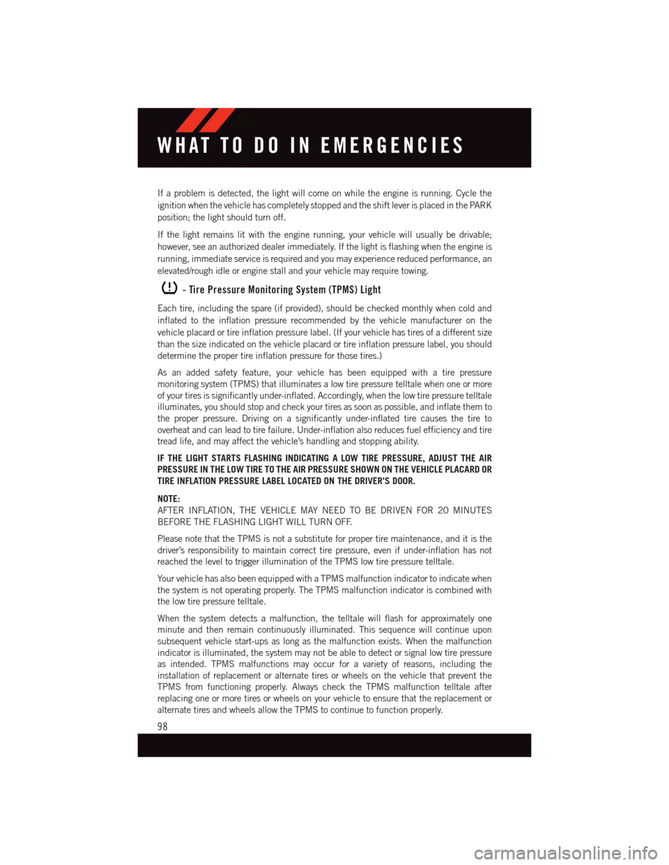
If a problem is detected, the light will come on while the engine is running. Cycle the
ignition when the vehicle has completely stopped and the shift lever is placed in the PARK
position; the light should turn off.
If the light remains lit with the engine running, your vehicle will usually be drivable;
however, see an authorized dealer immediately. If the light is flashing when the engine is
running, immediate service is required and you may experience reduced performance, an
elevated/rough idle or engine stall and your vehicle may require towing.
-TirePressureMonitoringSystem(TPMS)Light
Each tire, including the spare (if provided), should be checked monthly when cold and
inflated to the inflation pressure recommended by the vehicle manufacturer on the
vehicle placard or tire inflation pressure label. (If your vehicle has tires of a different size
than the size indicated on the vehicle placard or tire inflation pressure label, you should
determine the proper tire inflation pressure for those tires.)
As an added safety feature, your vehicle has been equipped with a tire pressure
monitoring system (TPMS) that illuminates a low tire pressure telltale when one or more
of your tires is significantly under-inflated. Accordingly, when the low tire pressure telltale
illuminates, you should stop and check your tires as soon as possible, and inflate them to
the proper pressure. Driving on a significantly under-inflated tire causes the tire to
overheat and can lead to tire failure. Under-inflation also reduces fuel efficiency and tire
tread life, and may affect the vehicle’s handling and stopping ability.
IF THE LIGHT STARTS FLASHING INDICATING A LOW TIRE PRESSURE, ADJUST THE AIR
PRESSURE IN THE LOW TIRE TO THE AIR PRESSURE SHOWN ON THE VEHICLE PLACARD OR
TIRE INFLATION PRESSURE LABEL LOCATED ON THE DRIVER'S DOOR.
NOTE:
AFTER INFLATION, THE VEHICLE MAY NEED TO BE DRIVEN FOR 20 MINUTES
BEFORE THE FLASHING LIGHT WILL TURN OFF.
Please note that the TPMS is not a substitute for proper tire maintenance, and it is the
driver’s responsibility to maintain correct tire pressure, even if under-inflation has not
reached the level to trigger illumination of the TPMS low tire pressure telltale.
Yo u r v e h i c l e h a s a l s o b e e n e q u i p p e d w i t h a T P M S m a l f u n c t i o n i n d i c a t o r t o i n d i c a t e w h e n
the system is not operating properly. The TPMS malfunction indicator is combined with
the low tire pressure telltale.
When the system detects a malfunction, the telltale will flash for approximately one
minute and then remain continuously illuminated. This sequence will continue upon
subsequent vehicle start-ups as long as the malfunction exists. When the malfunction
indicator is illuminated, the system may not be able to detect or signal low tire pressure
as intended. TPMS malfunctions may occur for a variety of reasons, including the
installation of replacement or alternate tires or wheels on the vehicle that prevent the
TPMS from functioning properly. Always check the TPMS malfunction telltale after
replacing one or more tires or wheels on your vehicle to ensure that the replacement or
alternate tires and wheels allow the TPMS to continue to function properly.
WHAT TO DO IN EMERGENCIES
98
Page 101 of 164
NOTE:
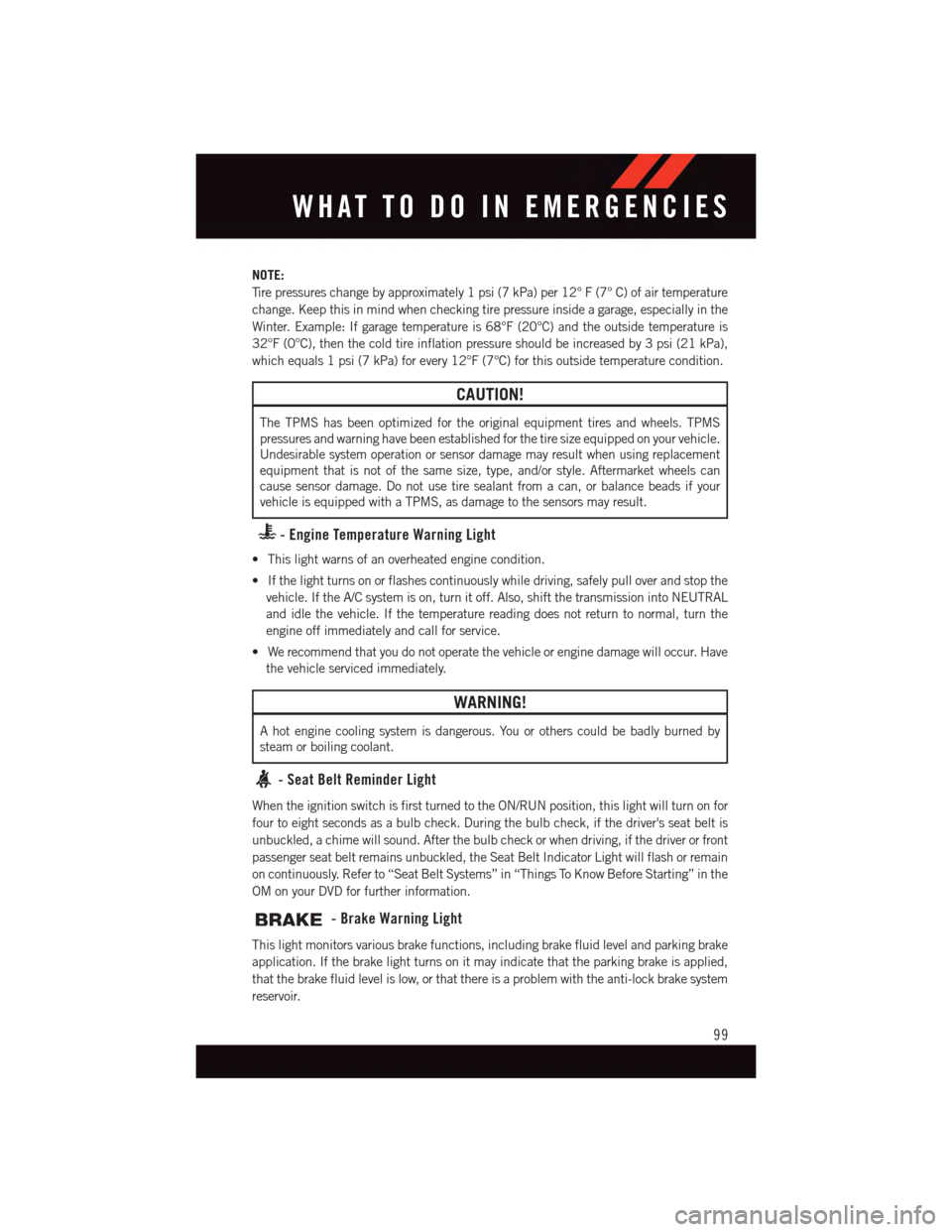
Ti r e p r e s s u r e s c h a n g e b y a p p r o x i m a t e l y 1 p s i ( 7 k P a ) p e r 1 2 ° F ( 7 ° C ) o f a i r t e m p e r a t u r e
change. Keep this in mind when checking tire pressure inside a garage, especially in the
Winter. Example: If garage temperature is 68°F (20°C) and the outside temperature is
32°F (0°C), then the cold tire inflation pressure should be increased by 3 psi (21 kPa),
which equals 1 psi (7 kPa) for every 12°F (7°C) for this outside temperature condition.
CAUTION!
The TPMS has been optimized for the original equipment tires and wheels. TPMS
pressures and warning have been established for the tire size equipped on your vehicle.
Undesirable system operation or sensor damage may result when using replacement
equipment that is not of the same size, type, and/or style. Aftermarket wheels can
cause sensor damage. Do not use tire sealant from a can, or balance beads if your
vehicle is equipped with a TPMS, as damage to the sensors may result.
-EngineTemperatureWarningLight
•Thislightwarnsofanoverheatedenginecondition.
•Ifthelightturnsonorflashescontinuouslywhiledriving,safelypulloverandstopthe
vehicle. If the A/C system is on, turn it off. Also, shift the transmission into NEUTRAL
and idle the vehicle. If the temperature reading does not return to normal, turn the
engine off immediately and call for service.
•Werecommendthatyoudonotoperatethevehicleorenginedamagewilloccur.Have
the vehicle serviced immediately.
WARNING!
Ahotenginecoolingsystemisdangerous.Youorotherscouldbebadlyburnedby
steam or boiling coolant.
-SeatBeltReminderLight
When the ignition switch is first turned to the ON/RUN position, this light will turn on for
four to eight seconds as a bulb check. During the bulb check, if the driver's seat belt is
unbuckled, a chime will sound. After the bulb check or when driving, if the driver or front
passenger seat belt remains unbuckled, the Seat Belt Indicator Light will flash or remain
on continuously. Refer to “Seat Belt Systems” in “Things To Know Before Starting” in the
OM on your DVD for further information.
-BrakeWarningLight
This light monitors various brake functions, including brake fluid level and parking brake
application. If the brake light turns on it may indicate that the parking brake is applied,
that the brake fluid level is low, or that there is a problem with the anti-lock brake system
reservoir.
WHAT TO DO IN EMERGENCIES
99
Page 102 of 164
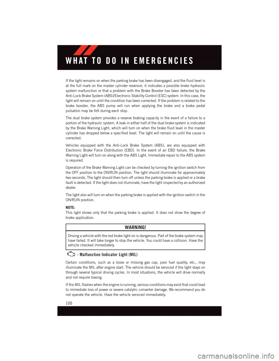
If the light remains on when the parking brake has been disengaged, and the fluid level is
at the full mark on the master cylinder reservoir, it indicates a possible brake hydraulic
system malfunction or that a problem with the Brake Booster has been detected by the
Anti-Lock Brake System (ABS)/Electronic Stability Control (ESC) system. In this case, the
light will remain on until the condition has been corrected. If the problem is related to the
brake booster, the ABS pump will run when applying the brake and a brake pedal
pulsation may be felt during each stop.
The dual brake system provides a reserve braking capacity in the event of a failure to a
portion of the hydraulic system. A leak in either half of the dual brake system is indicated
by the Brake Warning Light, which will turn on when the brake fluid level in the master
cylinder has dropped below a specified level. The light will remain on until the cause is
corrected.
Vehicles equipped with the Anti-Lock Brake System (ABS), are also equipped with
Electronic Brake Force Distribution (EBD). In the event of an EBD failure, the Brake
Warning Light will turn on along with the ABS Light. Immediate repair to the ABS system
is required.
Operation of the Brake Warning Light can be checked by turning the ignition switch from
the OFF position to the ON/RUN position. The light should illuminate for approximately
two seconds. The light should then turn off unless the parking brake is applied or a brake
fault is detected. If the light does not illuminate, have the light inspected by an authorized
dealer.
The light also will turn on when the parking brake is applied with the ignition switch in the
ON/RUN position.
NOTE:
This light shows only that the parking brake is applied. It does not show the degree of
brake application.
WARNING!
Driving a vehicle with the red brake light on is dangerous. Part of the brake system may
have failed. It will take longer to stop the vehicle. You could have a collision. Have the
vehicle checked immediately.
-MalfunctionIndicatorLight(MIL)
Certain conditions, such as a loose or missing gas cap, poor fuel quality, etc., may
illuminate the MIL after engine start. The vehicle should be serviced if the light stays on
through several typical driving cycles. In most situations, the vehicle will drive normally
and not require towing.
If the MIL flashes when the engine is running, serious conditions may exist that could lead
to immediate loss of power or severe catalytic converter damage. We recommend you do
not operate the vehicle. Have the vehicle serviced immediately.
WHAT TO DO IN EMERGENCIES
100
Page 103 of 164
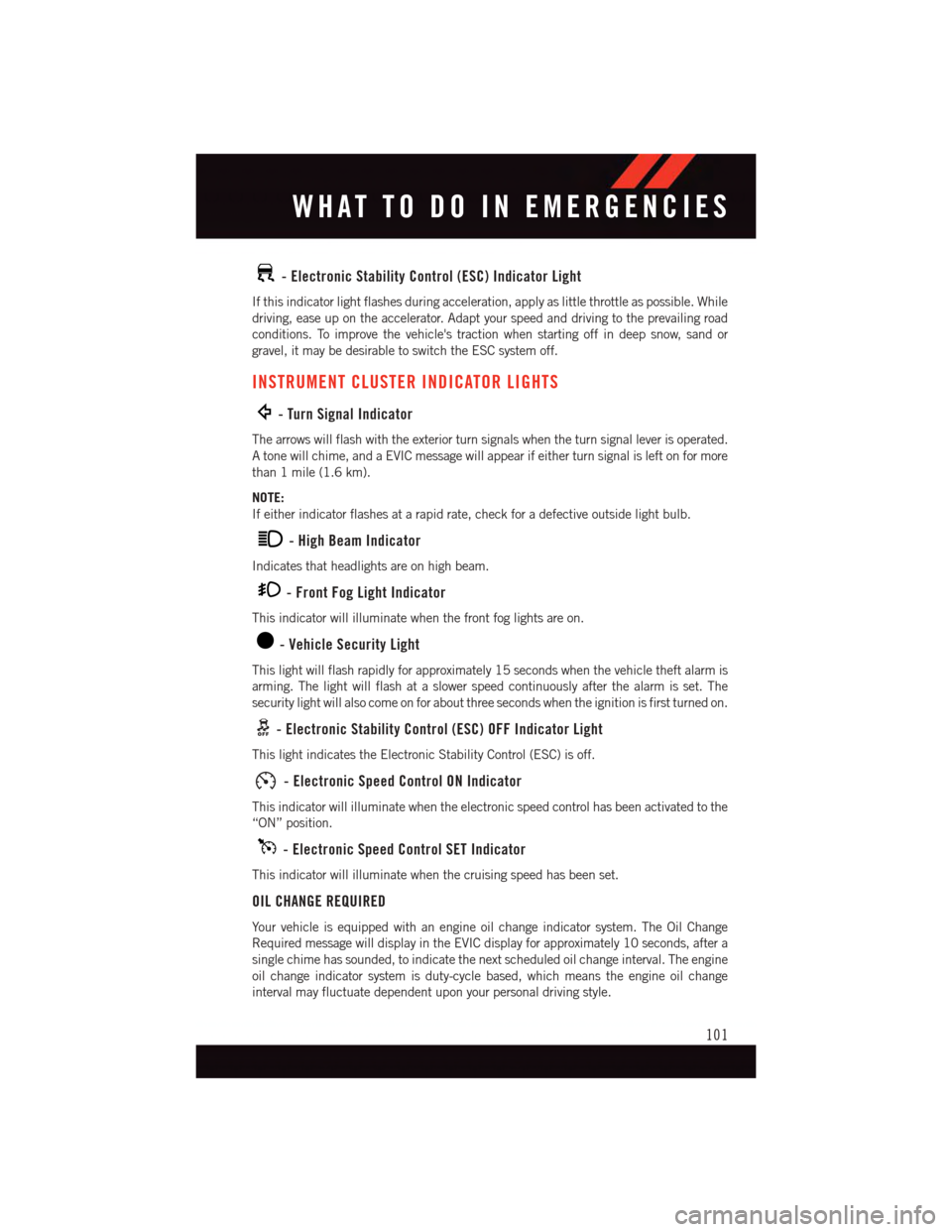
-ElectronicStabilityControl(ESC)IndicatorLight
If this indicator light flashes during acceleration, apply as little throttle as possible. While
driving, ease up on the accelerator. Adapt your speed and driving to the prevailing road
conditions. To improve the vehicle's traction when starting off in deep snow, sand or
gravel, it may be desirable to switch the ESC system off.
INSTRUMENT CLUSTER INDICATOR LIGHTS
-TurnSignalIndicator
The arrows will flash with the exterior turn signals when the turn signal lever is operated.
Atonewillchime,andaEVICmessagewillappearifeitherturnsignalisleftonformore
than 1 mile (1.6 km).
NOTE:
If either indicator flashes at a rapid rate, check for a defective outside light bulb.
-HighBeamIndicator
Indicates that headlights are on high beam.
-FrontFogLightIndicator
This indicator will illuminate when the front fog lights are on.
-VehicleSecurityLight
This light will flash rapidly for approximately 15 seconds when the vehicle theft alarm is
arming. The light will flash at a slower speed continuously after the alarm is set. The
security light will also come on for about three seconds when the ignition is first turned on.
-ElectronicStabilityControl(ESC)OFFIndicatorLight
This light indicates the Electronic Stability Control (ESC) is off.
-ElectronicSpeedControlONIndicator
This indicator will illuminate when the electronic speed control has been activated to the
“ON” position.
-ElectronicSpeedControlSETIndicator
This indicator will illuminate when the cruising speed has been set.
OIL CHANGE REQUIRED
Yo u r v e h i c l e i s e q u i p p e d w i t h a n e n g i n e o i l c h a n g e i n d i c a t o r s y s t e m . T h e O i l C h a n g e
Required message will display in the EVIC display for approximately 10 seconds, after a
single chime has sounded, to indicate the next scheduled oil change interval. The engine
oil change indicator system is duty-cycle based, which means the engine oil change
interval may fluctuate dependent upon your personal driving style.
WHAT TO DO IN EMERGENCIES
101
Page 104 of 164
Unless reset, this message will continue to display each time you turn the ignition switch
to the ON/RUN position or cycle the ignition to the ON/RUN position if equipped with
Keyless Enter-N-Go™. To turn off the message temporarily, press and release the MENU
button. To reset the oil change indicator system (after performing the scheduled mainte-
nance) refer to the following procedure.
Vehicles Equipped With Keyless Enter-N-Go™
1. Without pressing the brake pedal, push the ENGINE START/STOP button and cycle
the ignition to the ON/RUN position (do not start the engine.)
2. Fully depress the accelerator pedal, slowly, three times within 10 seconds.
3. Without pressing the brake pedal, push the ENGINE START/STOP button once to
return the ignition to the OFF/LOCK position.
Vehicles Not Equipped With Keyless Enter-N-Go™
1. Turn the ignition switch to the ON/RUN position (do not start the engine.)
2. Fully depress the accelerator pedal, slowly, three times within 10 seconds.
3. Turn the ignition switch to the OFF/LOCK position.
NOTE:
If the indicator message illuminates when you start the engine, the oil change indicator
system did not reset. If necessary, repeat these steps.
Resetting The Light After Servicing
Vehicles Equipped With Keyless Enter-N-Go™
1. Without pressing the brake pedal, push the ENGINE START/STOP button and cycle
the ignition to the ON/RUN position (do not start the engine.)
2. Fully depress the accelerator pedal, slowly, three times within 10 seconds.
3. Without pressing the brake pedal, push the ENGINE START/STOP button once to
return the ignition to the OFF/LOCK position.
Vehicles Not Equipped With Keyless Enter-N-Go™
1. Turn the ignition switch to the ON/RUN position (do not start the engine.)
2. Fully depress the accelerator pedal, slowly, three times within 10 seconds.
3. Turn the ignition switch to the OFF/LOCK position.
NOTE:
If the indicator message illuminates when you start the vehicle, the oil change indicator
system did not reset. If necessary, repeat this procedure.
WHAT TO DO IN EMERGENCIES
102
Page 120 of 164
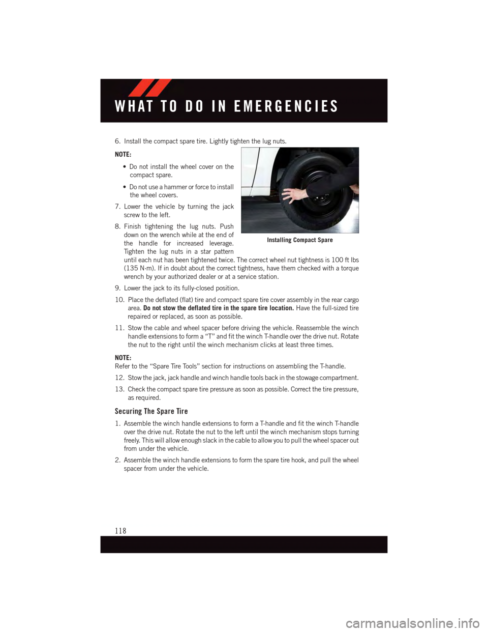
6. Install the compact spare tire. Lightly tighten the lug nuts.
NOTE:
•Donotinstallthewheelcoveronthe
compact spare.
•Donotuseahammerorforcetoinstall
the wheel covers.
7. Lower the vehicle by turning the jack
screw to the left.
8. Finish tightening the lug nuts. Push
down on the wrench while at the end of
the handle for increased leverage.
Ti g h t e n t h e l u g n u t s i n a s t a r p a t t e r n
until each nut has been tightened twice. The correct wheel nut tightness is 100 ft lbs
(135 N·m). If in doubt about the correct tightness, have them checked with a torque
wrench by your authorized dealer or at a service station.
9. Lower the jack to its fully-closed position.
10. Place the deflated (flat) tire and compact spare tire cover assembly in the rear cargo
area.Do not stow the deflated tire in the spare tire location.Have the full-sized tire
repaired or replaced, as soon as possible.
11. Stow the cable and wheel spacer before driving the vehicle. Reassemble the winch
handle extensions to form a “T” and fit the winch T-handle over the drive nut. Rotate
the nut to the right until the winch mechanism clicks at least three times.
NOTE:
Refer to the “Spare Tire Tools” section for instructions on assembling the T-handle.
12. Stow the jack, jack handle and winch handle tools back in the stowage compartment.
13. Check the compact spare tire pressure as soon as possible. Correct the tire pressure,
as required.
Securing The Spare Tire
1. Assemble the winch handle extensions to form a T-handle and fit the winch T-handle
over the drive nut. Rotate the nut to the left until the winch mechanism stops turning
freely. This will allow enough slack in the cable to allow you to pull the wheel spacer out
from under the vehicle.
2. Assemble the winch handle extensions to form the spare tire hook, and pull the wheel
spacer from under the vehicle.
Installing Compact Spare
WHAT TO DO IN EMERGENCIES
118
Page 121 of 164
3. Turn the compact spare tire so that the valve stem is down, and place the tire into the
spare tire/cover assembly. Slide the wheel spacer through the center of the wheel and
spare tire/cover assembly, so that the two retainer tabs snap out and engage the spare
tire cover on the opposite side.
4. Using the winch T-handle, rotate the drive nut to the right until the compact spare
tire/cover assembly is drawn into place against the underside of the vehicle.
5. Continue to rotate the nut to the right until you hear the winch mechanism click three
times. It cannot be overtightened. Check under the vehicle to ensure the compact
spare tire/cover assembly is positioned correctly against the underside of the vehicle.
Road Tire Installation
Vehicles Equipped With Wheel Covers
1. Mount the road tire on the axle.
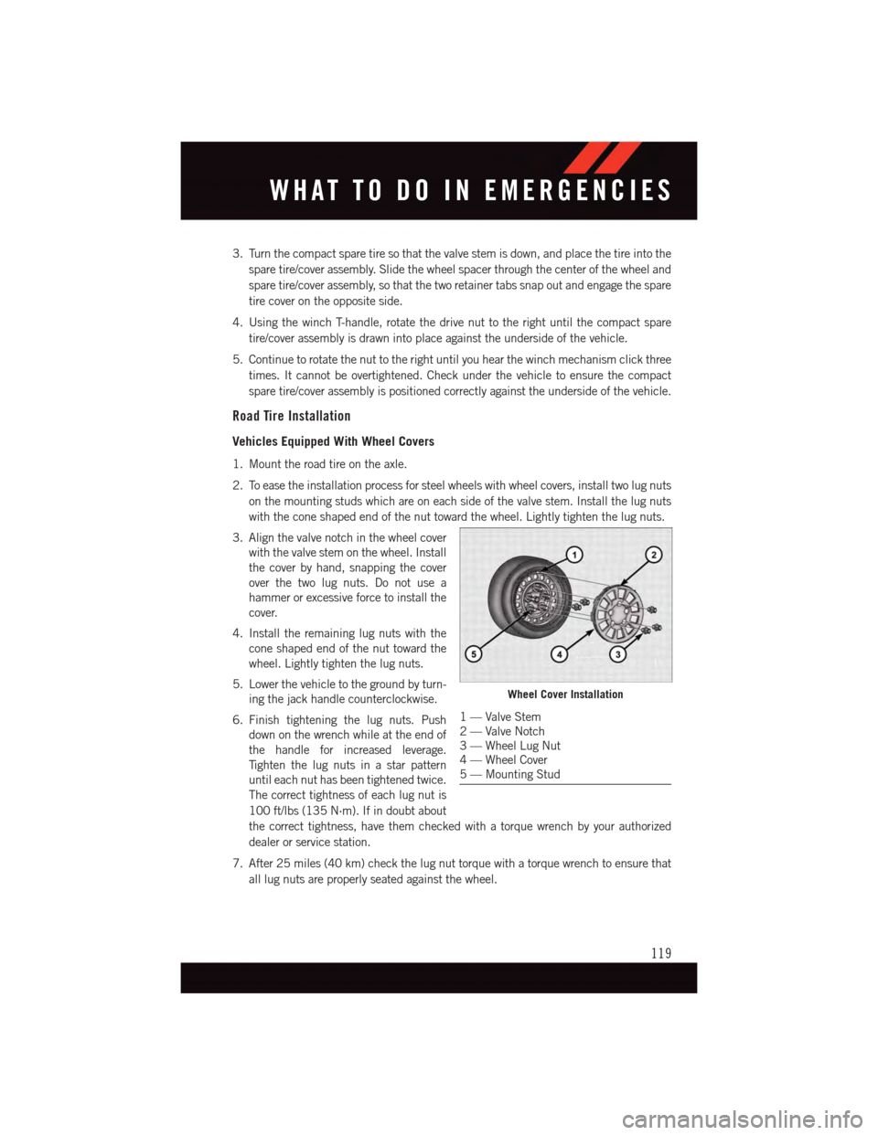
2. To ease the installation process for steel wheels with wheel covers, install two lug nuts
on the mounting studs which are on each side of the valve stem. Install the lug nuts
with the cone shaped end of the nut toward the wheel. Lightly tighten the lug nuts.
3. Align the valve notch in the wheel cover
with the valve stem on the wheel. Install
the cover by hand, snapping the cover
over the two lug nuts. Do not use a
hammer or excessive force to install the
cover.
4. Install the remaining lug nuts with the
cone shaped end of the nut toward the
wheel. Lightly tighten the lug nuts.
5. Lower the vehicle to the ground by turn-
ing the jack handle counterclockwise.
6. Finish tightening the lug nuts. Push
down on the wrench while at the end of
the handle for increased leverage.
Ti g h t e n t h e l u g n u t s i n a s t a r p a t t e r n
until each nut has been tightened twice.
The correct tightness of each lug nut is
100 ft/lbs (135 N·m). If in doubt about
the correct tightness, have them checked with a torque wrench by your authorized
dealer or service station.
7. After 25 miles (40 km) check the lug nut torque with a torque wrench to ensure that
all lug nuts are properly seated against the wheel.
Wheel Cover Installation
1—ValveStem2—ValveNotch3—WheelLugNut4—WheelCover5—MountingStud
WHAT TO DO IN EMERGENCIES
119
Page 122 of 164
Vehicles Without Wheel Covers
1. Mount the road tire on the axle.
2. Install the remaining lug nuts with the cone shaped end of the nut toward the wheel.
Lightly tighten the lug nuts.
3. Lower the vehicle to the ground by turning the jack handle counterclockwise.
4. Finish tightening the lug nuts. Push down on the wrench while at the end of the handle
for increased leverage. Tighten the lug nuts in a star pattern until each nut has been
tightened twice. The correct tightness of each lug nut is 100 ft/lbs (135 N·m). If in
doubt about the correct tightness, have them checked with a torque wrench by your
authorized dealer or service station.
5. After 25 miles (40 km) check the lug nut torque with a torque wrench to ensure that
all lug nuts are properly seated against the wheel.
CAUTION!
•ThewinchmechanismisdesignedforusewiththewinchT-handleonly.Useofair
wrench or other power tools is not recommended and can damage the winch.
•Donotattempttoraisethevehiclebyjackingonlocationsotherthanthose
indicated in the Jacking Instructions for this vehicle.
•Besuretomountthesparetirewiththevalvestemfacingoutward.Thevehicle
could be damaged if the spare tire is mounted incorrectly.
•Thecompactsparetire/coverassemblymustbeusedwhenthecompactsparetire
is stored. Failure to use this cover could drastically reduce the life of the compact
spare tire.
•Thewinchmechanismisdesignedspecificallytostowacompactsparetireonly.Do
not attempt to use the winch to stow the full size flat tire, or any other full-size tire.
Vehicle damage may result.
WHAT TO DO IN EMERGENCIES
120
Page 134 of 164
MAINTENANCE PROCEDURES
For information on the maintenance procedures for your vehicle, please refer to “Main-
tenance Procedures” in “Maintaining Your Vehicle” in your Owner’s Manual or applicable
supplement on the DVD for further details.
MAINTENANCE SCHEDULE
Yo u r v e h i c l e i s e q u i p p e d w i t h a n a u t o m a t i c o i l c h a n g e i n d i c a t o r s y s t e m . T h e o i l c h a n g e
indicator system will remind you that it is time to take your vehicle in for scheduled
maintenance.
Based on engine operation conditions, the oil change indicator message will illuminate.
This means that service is required for your vehicle. Operating conditions such as frequent
short-trips, trailer tow, extremely hot or cold ambient temperatures, and E85 fuel usage
will influence when the “Oil Change Required” message is displayed. Severe Operating
Conditions can cause the change oil message to illuminate as early as 3,500 miles
(5,600 km) since last reset. Have your vehicle serviced as soon as possible, within the
next 500 miles (805 km).
Yo u r a u t h o r i z e d d e a l e r w i l l r e s e t t h e o i l c h a n g e i n d i c a t o r m e s s a g e a f t e r c o m p l e t i n g t h e
scheduled oil change. If a scheduled oil change is performed by someone other than your
authorized dealer, the message can be reset by referring to the steps described under
“Instrument Cluster Warning Lights” in “What To Do In Emergencies” in this guide or
“Electronic Vehicle Information Center (EVIC)” in “Understanding Your Instrument
Panel” in your Owners Manual on the DVD for further information.
NOTE:
Under no circumstances should oil change intervals exceed 10,000 miles (16,000 km)
or twelve months, whichever comes first.
Severe Duty All Models
Change Engine Oil at 4000 miles (6,500 km) if the vehicle is operated in a dusty and off
road environment. This type of vehicle use is considered Severe Duty.
Once A Month Or Before A Long Trip:
•Checkengineoillevel.
•Checkwindshieldwasherfluidlevel.
•Checktirepressureandlookforunusualwearordamage.Rotatetiresatthefirstsign
of irregular wear, even if it occurs before the oil indicator system turns on.
•Checkthefluidlevelsofthecoolantreservoir,brakemastercylinder,andpower
steering and fill as needed.
•Checkfunctionofallinteriorandexteriorlights.
MAINTAINING YOUR VEHICLE
132
Page 141 of 164
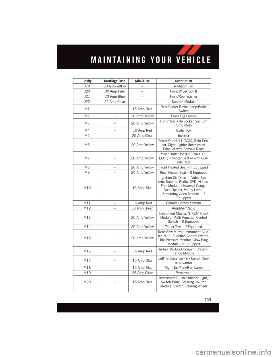
Cavity Cartridge Fuse Mini-FuseDescription
J19 60 Amp Yellow –Radiator Fan
J20 30 Amp Pink –Front Wiper LO/HI
J21 20 Amp Blue –Front/Rear Washer
J22 25 Amp Clear –Sunroof Module
M1–15AmpBlueRear Center Brake Lamp/BrakeSwitch
M2–20AmpYellow FrontFogLamps
M3–20AmpYellowFront/Rear Axle Locker, VacuumPump Motor
M4–10AmpRedTr a i l e r To w
M5–25AmpClearInverter
M6–20AmpYellowPower Outlet #1 (ACC), Rain Sen-sor, Cigar Lighter (InstrumentPanel or with Console Rear)
M7–20AmpYellowPower Outlet #2 (BATT/ACC SE-LECT) – Center Seat or with Con-sole Rear
M8–20AmpYellowFrontHeatedSeat–IfEquipped
M9–20AmpYellowRearHeatedSeat–IfEquipped
M10–15AmpBlue
Ignition Off Draw — Video Sys-tem, Satellite Radio, DVD, Hands-Free Module, Universal GarageDoor Opener, Vanity Lamp,Streaming Video Module – IfEquipped
M11–10AmpRedClimateControlSystem
M12–30AmpGreenAmplifier/Radio
M13–20AmpYellowInstrument Cluster, SIREN, ClockModule, Multi-Function ControlSwitch – If Equipped
M14–20AmpYellowTrailerTow–IfEquipped
M15–20AmpYellow
Rear View Mirror, Instrument Clus-ter, Multi-Function Control Switch,Ti r e P r e s s u r e M o n i t o r, G l o w P l u gModule – If Equipped
M16–10AmpRedAirbag Module/Occupant Classifi-cation Module
M17–15AmpBlueLeft Tail/License/Park Lamp, Run-ning Lamps
M18–15AmpBlueRightTail/Park/RunLamp
M19–25AmpClearPowertrain
M20–15AmpBlueInstrument Cluster Interior Light,Switch Bank, Steering ColumnModule, Switch Steering Wheel
MAINTAINING YOUR VEHICLE
139