ABS DODGE GRAND CARAVAN 2015 5.G User Guide
[x] Cancel search | Manufacturer: DODGE, Model Year: 2015, Model line: GRAND CARAVAN, Model: DODGE GRAND CARAVAN 2015 5.GPages: 164, PDF Size: 22.27 MB
Page 22 of 164
Supplemental Knee Air Bags
This vehicle is equipped with a Supplemental Driver Knee Air Bag mounted in the
instrument panel below the steering column. The Supplemental Driver Knee Air Bag
provides enhanced protection during a frontal impact by working together with the seat
belts, pretensioners, and Advanced Front Air Bags.
WARNING!
•Relyingontheairbagsalonecouldleadtomoresevereinjuriesinacollision.The
air bags work with your seat belt to restrain you properly. In some collisions, the air
bags won't deploy at all. Always wear your seat belts even though you have air bags.
•BeingtooclosetothesteeringwheelorinstrumentpanelduringAdvancedFrontAir
Bag deployment could cause serious injury, including death. Air bags need room to
inflate. Sit back, comfortably extending your arms to reach the steering wheel or
instrument panel.
•Noobjectsshouldbeplacedoverorneartheairbagontheinstrumentpanelor
steering wheel because any such objects could cause harm if the vehicle is in a
collision severe enough to cause the air bag to inflate.
Supplemental Side Air Bags
•ThisvehicleisequippedwithSupplementalSeat-MountedSideAirBags(SABs)
located in the outboard side of the front seats. The SABs are marked with a SRS
AIRBAG or AIRBAG label sewn into the outboard side of the seats.
•ThisvehicleisequippedwithSupplementalSideAirBagInflatableCurtains(SABICs)
located above the side windows. The trim covering the SABICs is labeled SRS AIRBAG
or AIRBAG. The SABICs may help reduce the risk of partial or complete ejection of
vehicle occupants through side windows in certain side impact events.
•TheSABICsandSABs(“SideAirBags”)aredesignedtoactivateincertainside
impacts and certain rollover events. The Occupant Restraint Controller (“ORC”)
determines whether the deployment of the Side Air Bags in a particular side impact or
rollover event is appropriate, based on the severity and type of collision. Vehicle damage
by itself is not a good indicator of whether or not Side Air Bags should have deployed.
GETTING STARTED
20
Page 67 of 164
•Selectthe“AutoColorMode”buttononthetouchscreentoswitchtoautomatic
daytime/nighttime mode and to control the brightness of the display using the dimmer
switch of the vehicle.
•Pressthe“Exit”buttononthetouchscreentosaveyoursettings.
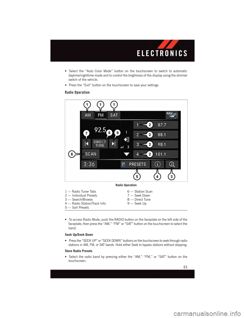
Radio Operation
•ToaccessRadioMode,pushtheRADIObuttononthefaceplateontheleftsideofthe
faceplate, then press the “AM,” “FM” or “SAT” button on the touchscreen to select the
band.
Seek Up/Seek Down
•Press the “SEEK UP” or “SEEK DOWN” buttons on the touchscreen to seek through radio
stations in AM, FM, or SAT bands. Hold either Seek to bypass stations without stopping.
Store Radio Presets
•Selecttheradiobandbypressingeitherthe“AM,”“FM,”or“SAT”buttononthe
touchscreen.
Radio Operation
1—RadioTunerTabs6—StationScan2—IndividualPresets7—SeekDown3—Search/Browse8—DirectTune4—RadioStation/TrackInfo9—SeekUp5—SortPresets
ELECTRONICS
65
Page 68 of 164
•Findthestationtostorebyeitherpressingthe“SEEKUP”or“SEEKDOWN”buttonson the touchscreen, pressing the “Scan” button on the touchscreen, or by using the“Direct Tune” button on the touchscreen.
•Oncethestationisfound,pressandholdoneofthe“PRESETS”buttonsonthetouchscreen in the list to the right, until the preset key flashes and the station text onthe button on the touchscreen changes.
NOTE:
If the Presets are not visible on the right side of the screen, press the “PRESETS” button
on the touchscreen.
CD/DVD Disc Operation
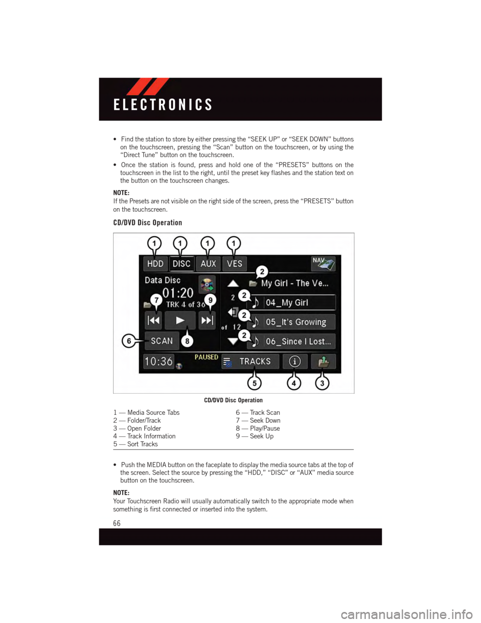
•PushtheMEDIAbuttononthefaceplatetodisplaythemediasourcetabsatthetopofthe screen. Select the source by pressing the “HDD,” “DISC” or “AUX” media sourcebutton on the touchscreen.
NOTE:
Yo u r To u c h s c r e e n R a d i o w i l l u s u a l l y a u t o m a t i c a l l y s w i t c h t o t h e a p p r o p r i a t e m o d e w h e n
something is first connected or inserted into the system.
CD/DVD Disc Operation
1—MediaSourceTabs6—TrackScan2—Folder/Track7—SeekDown3—OpenFolder8—Play/Pause4—TrackInformation9—SeekUp5—SortTracks
ELECTRONICS
66
Page 71 of 164
•Pressthedesiredpicturesorpressthe“All”buttononthetouchscreenforallpictures.
Confirm your selections by pressing the “SAVE” button on the touchscreen.
NOTE:
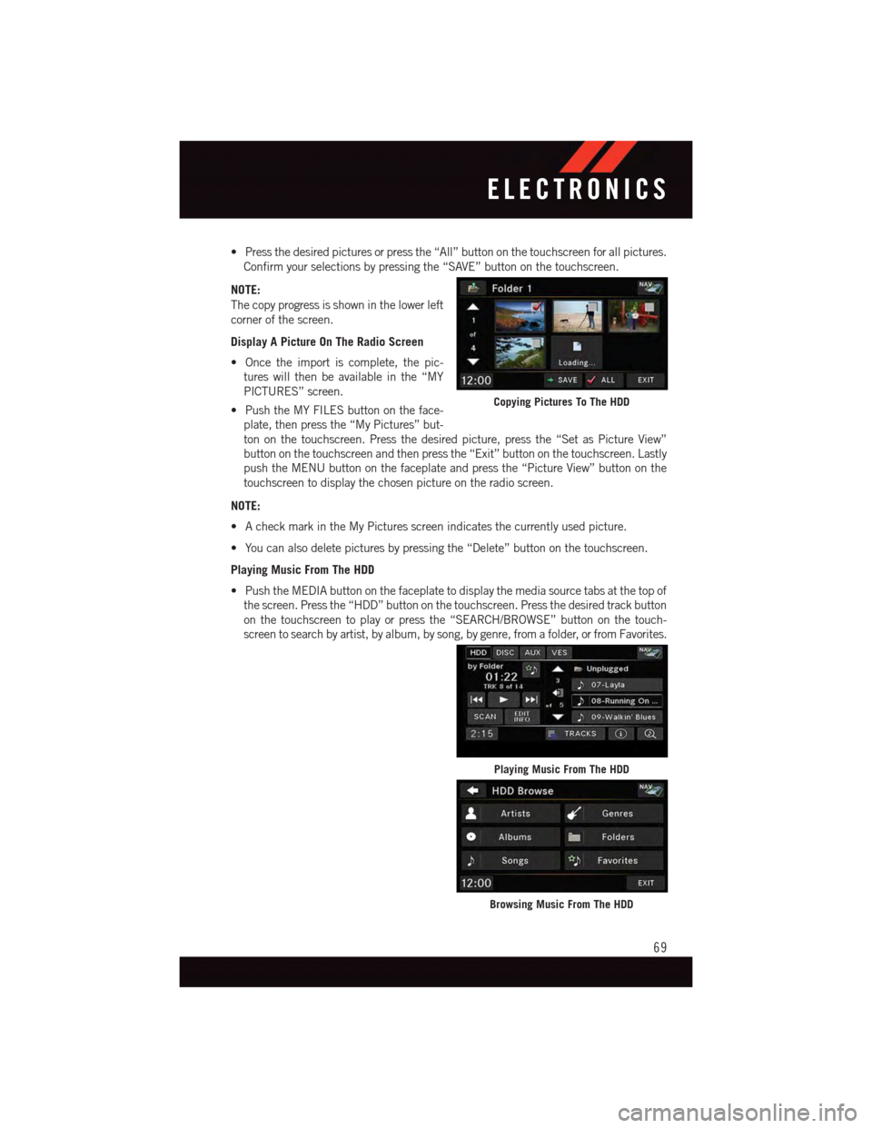
The copy progress is shown in the lower left
corner of the screen.
Display A Picture On The Radio Screen
•Oncetheimportiscomplete,thepic-
tures will then be available in the “MY
PICTURES” screen.
•PushtheMYFILESbuttonontheface-
plate, then press the “My Pictures” but-
ton on the touchscreen. Press the desired picture, press the “Set as Picture View”
button on the touchscreen and then press the “Exit” button on the touchscreen. Lastly
push the MENU button on the faceplate and press the “Picture View” button on the
touchscreen to display the chosen picture on the radio screen.
NOTE:
•AcheckmarkintheMyPicturesscreenindicatesthecurrentlyusedpicture.
•Youcanalsodeletepicturesbypressingthe“Delete”buttononthetouchscreen.
Playing Music From The HDD
•PushtheMEDIAbuttononthefaceplatetodisplaythemediasourcetabsatthetopof
the screen. Press the “HDD” button on the touchscreen. Press the desired track button
on the touchscreen to play or press the “SEARCH/BROWSE” button on the touch-
screen to search by artist, by album, by song, by genre, from a folder, or from Favorites.
Copying Pictures To The HDD
Playing Music From The HDD
Browsing Music From The HDD
ELECTRONICS
69
Page 99 of 164
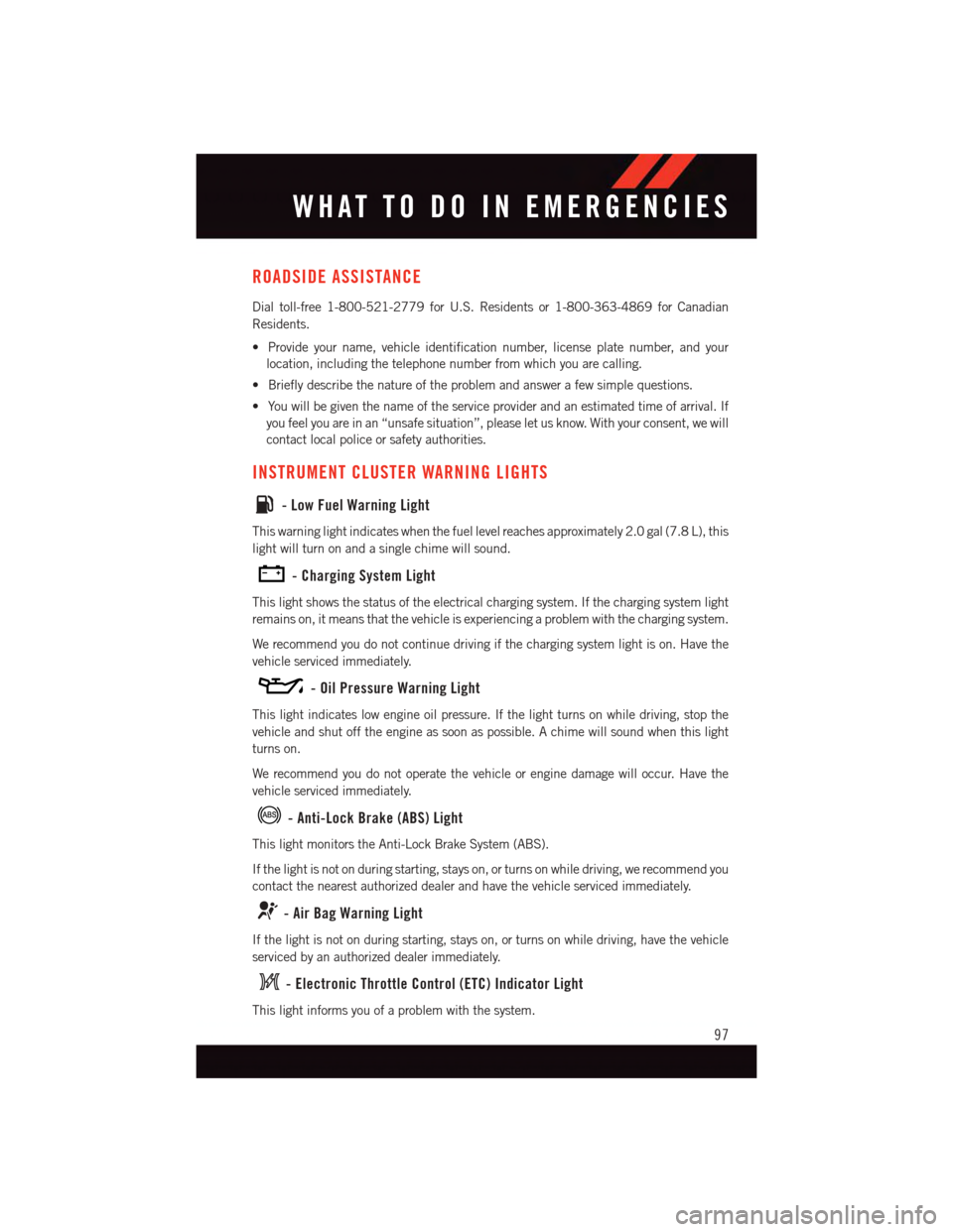
ROADSIDE ASSISTANCE
Dial toll-free 1-800-521-2779 for U.S. Residents or 1-800-363-4869 for Canadian
Residents.
•Provideyourname,vehicleidentificationnumber,licenseplatenumber,andyour
location, including the telephone number from which you are calling.
•Brieflydescribethenatureoftheproblemandanswerafewsimplequestions.
•Youwillbegiventhenameoftheserviceproviderandanestimatedtimeofarrival.If
you feel you are in an “unsafe situation”, please let us know. With your consent, we will
contact local police or safety authorities.
INSTRUMENT CLUSTER WARNING LIGHTS
-LowFuelWarningLight
This warning light indicates when the fuel level reaches approximately 2.0 gal (7.8 L), this
light will turn on and a single chime will sound.
-ChargingSystemLight
This light shows the status of the electrical charging system. If the charging system light
remains on, it means that the vehicle is experiencing a problem with the charging system.
We recommend you do not continue driving if the charging system light is on. Have the
vehicle serviced immediately.
-OilPressureWarningLight
This light indicates low engine oil pressure. If the light turns on while driving, stop the
vehicle and shut off the engine as soon as possible. A chime will sound when this light
turns on.
We recommend you do not operate the vehicle or engine damage will occur. Have the
vehicle serviced immediately.
-Anti-LockBrake(ABS)Light
This light monitors the Anti-Lock Brake System (ABS).
If the light is not on during starting, stays on, or turns on while driving, we recommend you
contact the nearest authorized dealer and have the vehicle serviced immediately.
-AirBagWarningLight
If the light is not on during starting, stays on, or turns on while driving, have the vehicle
serviced by an authorized dealer immediately.
-ElectronicThrottleControl(ETC)IndicatorLight
This light informs you of a problem with the system.
WHAT TO DO IN EMERGENCIES
97
Page 102 of 164
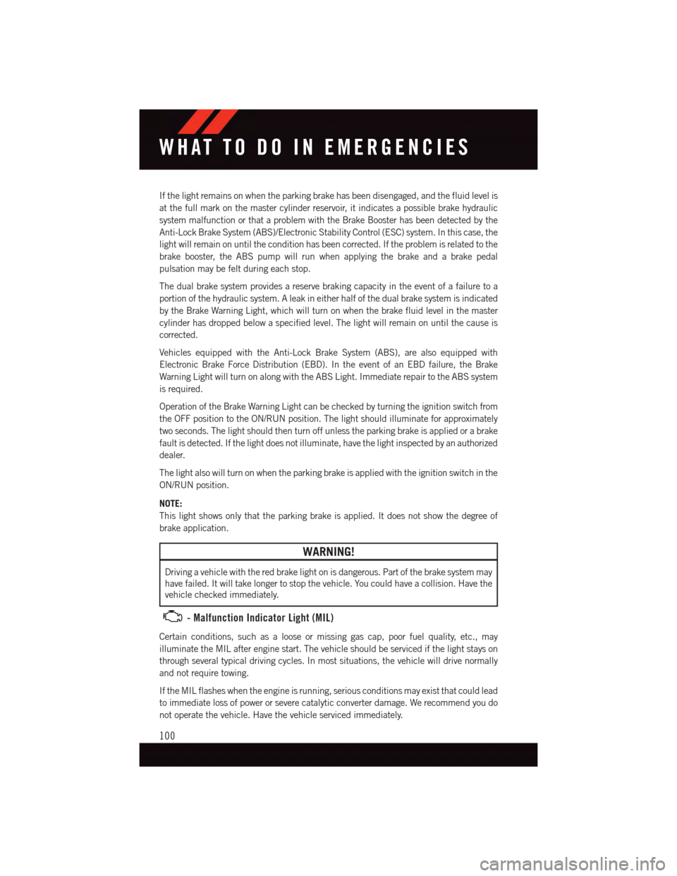
If the light remains on when the parking brake has been disengaged, and the fluid level is
at the full mark on the master cylinder reservoir, it indicates a possible brake hydraulic
system malfunction or that a problem with the Brake Booster has been detected by the
Anti-Lock Brake System (ABS)/Electronic Stability Control (ESC) system. In this case, the
light will remain on until the condition has been corrected. If the problem is related to the
brake booster, the ABS pump will run when applying the brake and a brake pedal
pulsation may be felt during each stop.
The dual brake system provides a reserve braking capacity in the event of a failure to a
portion of the hydraulic system. A leak in either half of the dual brake system is indicated
by the Brake Warning Light, which will turn on when the brake fluid level in the master
cylinder has dropped below a specified level. The light will remain on until the cause is
corrected.
Vehicles equipped with the Anti-Lock Brake System (ABS), are also equipped with
Electronic Brake Force Distribution (EBD). In the event of an EBD failure, the Brake
Warning Light will turn on along with the ABS Light. Immediate repair to the ABS system
is required.
Operation of the Brake Warning Light can be checked by turning the ignition switch from
the OFF position to the ON/RUN position. The light should illuminate for approximately
two seconds. The light should then turn off unless the parking brake is applied or a brake
fault is detected. If the light does not illuminate, have the light inspected by an authorized
dealer.
The light also will turn on when the parking brake is applied with the ignition switch in the
ON/RUN position.
NOTE:
This light shows only that the parking brake is applied. It does not show the degree of
brake application.
WARNING!
Driving a vehicle with the red brake light on is dangerous. Part of the brake system may
have failed. It will take longer to stop the vehicle. You could have a collision. Have the
vehicle checked immediately.
-MalfunctionIndicatorLight(MIL)
Certain conditions, such as a loose or missing gas cap, poor fuel quality, etc., may
illuminate the MIL after engine start. The vehicle should be serviced if the light stays on
through several typical driving cycles. In most situations, the vehicle will drive normally
and not require towing.
If the MIL flashes when the engine is running, serious conditions may exist that could lead
to immediate loss of power or severe catalytic converter damage. We recommend you do
not operate the vehicle. Have the vehicle serviced immediately.
WHAT TO DO IN EMERGENCIES
100
Page 111 of 164
WARNING!
•Donotattempttosealatireonthesideofthevehicleclosesttotraffic.Pullfar
enough off the road to avoid the danger of being hit when using the Tire Service Kit.•DonotusetheTireServiceKitordrivethevehicleunderthefollowingcircum-
stances:
•Ifthepunctureinthetiretreadisapproximately1/4”.(6mm)orlarger.
•Ifthetirehasanysidewalldamage.
•Ifthetirehasanydamagefromdrivingwithextremelylowtirepressure.
•Ifthetirehasanydamagefromdrivingonaflattire.
•Ifthewheelhasanydamage.
•Ifyouareunsureoftheconditionofthetireorthewheel.
•KeeptheTireServiceKitawayfromopenflamesorheatsource.
•AlooseTireServiceKitthrownforwardinacollisionorhardstopcouldendangerthe
occupants of the vehicle. Always stow the Tire Service Kit in the place provided.
Failure to follow these warnings can result in injuries that are serious or fatal to you,
your passengers, and others around you.
•TakecarenottoallowthecontentsoftheTireServiceKittocomeincontactwith
hair, eyes, or clothing. The Tire Service Kit is harmful if inhaled, swallowed, or
absorbed through the skin. It causes skin, eye, and respiratory irritation. Flush
immediately with plenty of water if there is any contact with eyes or skin. Change
clothing as soon as possible, if there is any contact with clothing.
•TheTireServiceKitSealantsolutioncontainslatex.Incaseofanallergicreaction
or rash, consult a physician immediately. Keep the Tire Service Kit out of reach of
children. If swallowed, rinse mouth immediately with plenty of water and drink
plenty of water. Do not induce vomiting! Consult a physician immediately.
•TheTireServiceKitisnotapermanentflattirerepair.Havethetireinspectedand
repaired or replaced after using the Tire Service Kit. Do not exceed 55 mph
(88 km/h) until the tire is repaired or replaced. Failure to follow this warning can
result in injuries that are serious or fatal to you, your passengers, and others around
you.
WHAT TO DO IN EMERGENCIES
109
Page 117 of 164
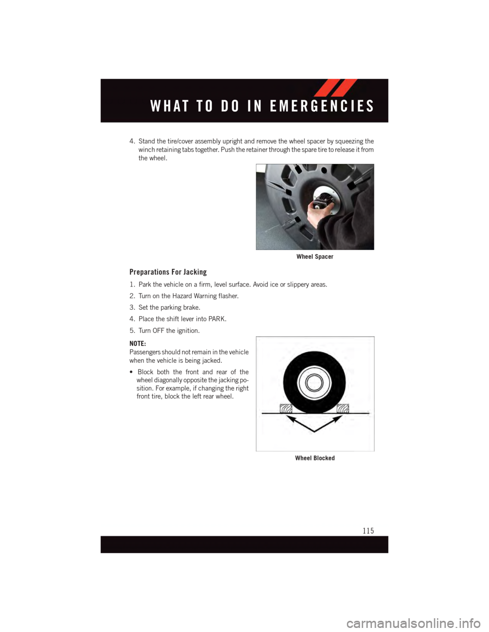
4. Stand the tire/cover assembly upright and remove the wheel spacer by squeezing the
winch retaining tabs together. Push the retainer through the spare tire to release it from
the wheel.
Preparations For Jacking
1. Park the vehicle on a firm, level surface. Avoid ice or slippery areas.
2. Turn on the Hazard Warning flasher.
3. Set the parking brake.
4. Place the shift lever into PARK.
5. Turn OFF the ignition.
NOTE:
Passengers should not remain in the vehicle
when the vehicle is being jacked.
•Blockboththefrontandrearofthe
wheel diagonally opposite the jacking po-
sition. For example, if changing the right
front tire, block the left rear wheel.
Wheel Spacer
Wheel Blocked
WHAT TO DO IN EMERGENCIES
115
Page 119 of 164
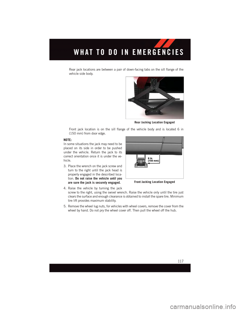
Rear jack locations are between a pair of down-facing tabs on the sill flange of the
vehicle side body.
Front jack location is on the sill flange of the vehicle body and is located 6 in
(150 mm) from door edge.
NOTE:
In some situations the jack may need to be
placed on its side in order to be pushed
under the vehicle. Return the jack to its
correct orientation once it is under the ve-
hicle.
3. Place the wrench on the jack screw and
turn to the right until the jack head is
properly engaged in the described loca-
tion.Do not raise the vehicle until you
are sure the jack is securely engaged.
4. Raise the vehicle by turning the jack
screw to the right, using the swivel wrench. Raise the vehicle only until the tire just
clears the surface and enough clearance is obtained to install the spare tire. Minimum
tire lift provides maximum stability.
5. Remove the wheel lug nuts, for vehicles with wheel covers, remove the cover from the
wheel by hand. Do not pry the wheel cover off. Then pull the wheel off the hub.
Rear Jacking Location Engaged
Front Jacking Location Engaged
WHAT TO DO IN EMERGENCIES
117
Page 121 of 164
3. Turn the compact spare tire so that the valve stem is down, and place the tire into the
spare tire/cover assembly. Slide the wheel spacer through the center of the wheel and
spare tire/cover assembly, so that the two retainer tabs snap out and engage the spare
tire cover on the opposite side.
4. Using the winch T-handle, rotate the drive nut to the right until the compact spare
tire/cover assembly is drawn into place against the underside of the vehicle.
5. Continue to rotate the nut to the right until you hear the winch mechanism click three
times. It cannot be overtightened. Check under the vehicle to ensure the compact
spare tire/cover assembly is positioned correctly against the underside of the vehicle.
Road Tire Installation
Vehicles Equipped With Wheel Covers
1. Mount the road tire on the axle.
2. To ease the installation process for steel wheels with wheel covers, install two lug nuts
on the mounting studs which are on each side of the valve stem. Install the lug nuts
with the cone shaped end of the nut toward the wheel. Lightly tighten the lug nuts.
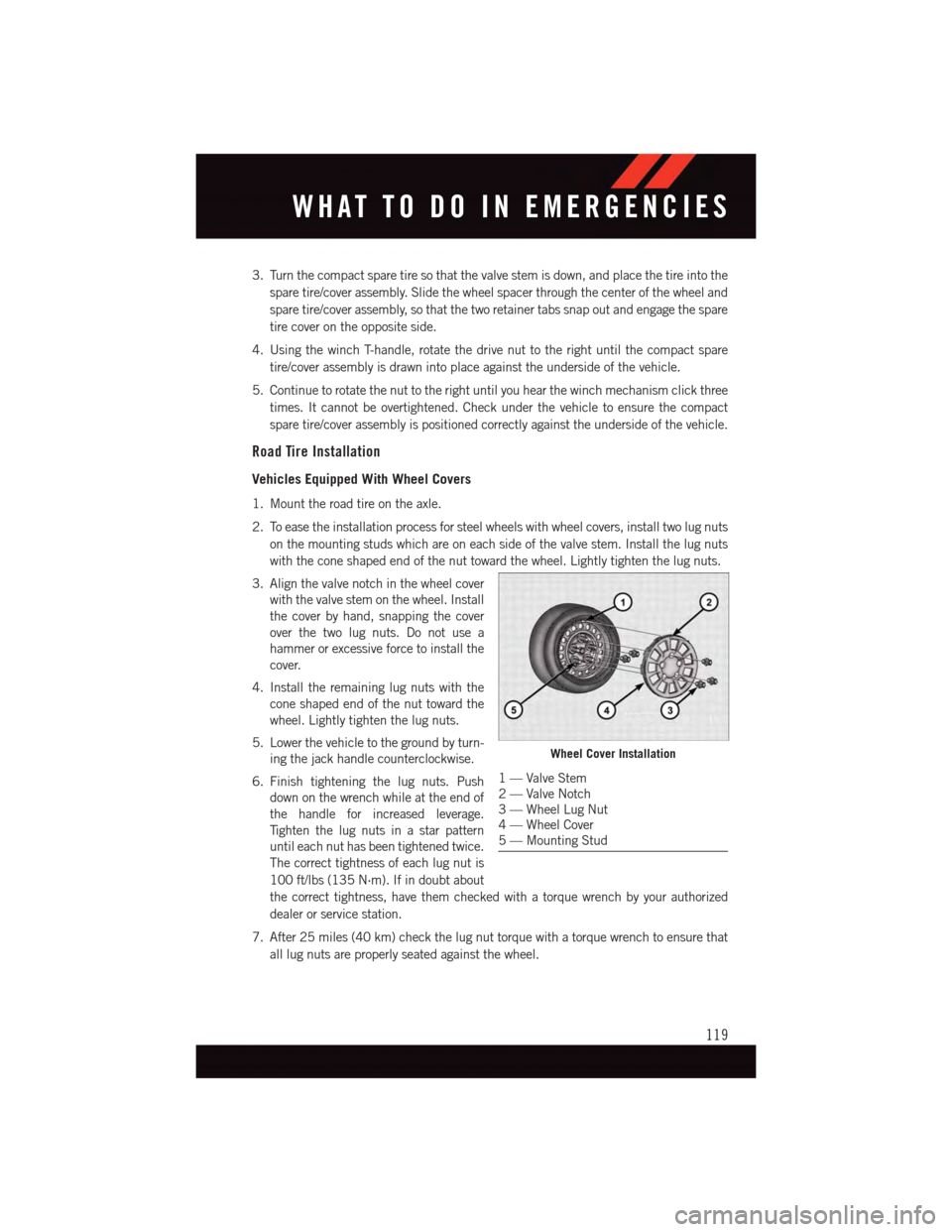
3. Align the valve notch in the wheel cover
with the valve stem on the wheel. Install
the cover by hand, snapping the cover
over the two lug nuts. Do not use a
hammer or excessive force to install the
cover.
4. Install the remaining lug nuts with the
cone shaped end of the nut toward the
wheel. Lightly tighten the lug nuts.
5. Lower the vehicle to the ground by turn-
ing the jack handle counterclockwise.
6. Finish tightening the lug nuts. Push
down on the wrench while at the end of
the handle for increased leverage.
Ti g h t e n t h e l u g n u t s i n a s t a r p a t t e r n
until each nut has been tightened twice.
The correct tightness of each lug nut is
100 ft/lbs (135 N·m). If in doubt about
the correct tightness, have them checked with a torque wrench by your authorized
dealer or service station.
7. After 25 miles (40 km) check the lug nut torque with a torque wrench to ensure that
all lug nuts are properly seated against the wheel.
Wheel Cover Installation
1—ValveStem2—ValveNotch3—WheelLugNut4—WheelCover5—MountingStud
WHAT TO DO IN EMERGENCIES
119