fuel cap DODGE GRAND CARAVAN 2020 Owners Manual
[x] Cancel search | Manufacturer: DODGE, Model Year: 2020, Model line: GRAND CARAVAN, Model: DODGE GRAND CARAVAN 2020Pages: 380, PDF Size: 14.92 MB
Page 6 of 380

4
ENGINE BREAK-IN RECOMMENDATIONS ...... 163
PARK BRAKE ..................................................... 164
AUTOMATIC TRANSMISSION............................ 165 Key Ignition Park Interlock ........................ 166Brake/Transmission Shift Interlock
System ........................................................ 166 Fuel Economy (ECON) Mode .....................167Six-Speed Automatic Transmission ..........167
Gear Ranges ..............................................168
POWER STEERING ............................................. 172
Power Steering Fluid Check ......................173
SPEED CONTROL — IF EQUIPPED .................... 173
To Activate .................................................. 174To Set A Desired Speed .............................174To Vary The Speed Setting ........................ 174To Accelerate For Passing ........................ 175To Resume Speed......................................175
To Deactivate .............................................175
PARKSENSE REAR PARK ASSIST
— IF EQUIPPED ................................................... 175
ParkSense Sensors ...................................176
ParkSense Warning Display ......................176
ParkSense Display ..................................... 176Enabling/Disabling ParkSense ................. 178
Service The ParkSense Rear Park Assist
System ........................................................ 178 Cleaning The ParkSense System ..............178
ParkSense System Usage Precautions ....178 PARKVIEW REAR BACK UP CAMERA ............. 179
REFUELING THE VEHICLE ................................. 181
Loose Fuel Filler Cap Message ................. 181
VEHICLE LOADING ............................................182
Certification Label ..................................... 182
TRAILER TOWING ............................................... 183
Common Towing Definitions ..................... 183Trailer Hitch Classification ........................ 184
Trailer Towing Weights
(Maximum Trailer Weight Ratings) .......... 186 Trailer And Tongue Weight ....................... 186
Towing Requirements ............................... 187Towing Tips ................................................ 189
RECREATIONAL TOWING
(BEHIND MOTORHOME, ETC.) .......................... 191
Towing This Vehicle Behind Another
Vehicle ........................................................ 191 Recreational Towing — All Models ............ 191
DRIVING TIPS ...................................................... 192
Driving On Slippery Surfaces .................... 192
Driving Through Water .............................. 192
IN CASE OF EMERGENCY
HAZARD WARNING FLASHERS .......................194
BULB REPLACEMENT ........................................ 194Replacement Bulbs .................................. 194Replacing Exterior Bulbs ........................... 196 FUSES .................................................................. 197
General Information .................................. 198
Totally Integrated Power Module
(Fuses) ....................................................... 198
JACKING AND TIRE CHANGING ....................... 202
Jack Location ............................................. 203
Spare Tire Tools ......................................... 203To Access Spare Tire Winch Drive Nut ..... 203Spare Tire Removal .................................. 205
Spare Tire Removal Instructions .............. 205
Preparations For Jacking ......................... 206
Jacking Instructions................................... 206
Securing The Compact Spare Tire ............ 210
Road Tire Installation ................................ 211
TIRE SERVICE KIT — IF EQUIPPED ................... 212
JUMP STARTING ................................................ 219
Preparations For Jump Start ..................... 219
Jump Starting Procedure .......................... 220
IF YOUR ENGINE OVERHEATS ......................... 221
GEAR SELECTOR OVERRIDE ........................... 222
FREEING A STUCK VEHICLE ............................. 223
TOWING A DISABLED VEHICLE ....................... 224
ENHANCED ACCIDENT RESPONSE
SYSTEM (EARS) ................................................. 225
EVENT DATA RECORDER (EDR) ....................... 225
20_RT_OM_EN_USC_t.book Page 4
Page 7 of 380

5
SERVICING AND MAINTENANCE
SCHEDULED SERVICING .................................. 226Maintenance Plan......................................227
ENGINE COMPARTMENT .................................. 231
Engine Compartment — 3.6L ....................231
Checking Oil Level......................................232
Adding Washer Fluid .................................232
Maintenance-Free Battery .......................232
Pressure Washing ......................................233
DEALER SERVICE .............................................. 233
Engine Oil .................................................. 233Engine Oil Filter ..........................................234Engine Air Cleaner Filter ...........................235
Air Conditioner Maintenance ...................235Accessory Drive Belt Inspection................236Body Lubrication ........................................237
Windshield Wiper Blades ..........................238
Exhaust System ........................................238
Cooling System ..........................................239Brake System ............................................242
Automatic Transmission ............................243
RAISING THE VEHICLE ...................................... 244
TIRES ................................................................... 245
Tire Safety Information .............................245Tires — General Information .....................252Tire Types ...................................................256
Spare Tires — If Equipped .........................257
Wheel And Wheel Trim Care ....................259
Tire Chains and Traction Devices ............260
Tire Rotation Recommendations .............261 DEPARTMENT OF TRANSPORTATION
UNIFORM TIRE QUALITY GRADES .................. 261
Treadwear .................................................. 261
Traction Grades ......................................... 261
Temperature Grades ................................. 262
VEHICLE STORAGE .............................................262
BODYWORK ........................................................ 262
Protection From Atmospheric Agents....... 262
Body And Underbody Maintenance .......... 263Preserving The Bodywork .......................... 263
INTERIORS ......................................................... 264
Seats And Fabric Parts .............................. 264
Plastic And Coated Parts ........................... 264
Glass Surfaces .......................................... 265Cleaning The Instrument Panel
Cupholders ................................................. 265
TECHNICAL SPECIFICATIONS
IDENTIFICATION DATA .......................................266
Vehicle Identification Number .................. 266
BRAKE SYSTEM .................................................. 266
WHEEL AND TIRE TORQUE
SPECIFICATIONS ................................................ 266
Torque Specifications ................................ 266
FUEL REQUIREMENTS ......................................267
3.6L Engine ................................................ 267
Reformulated Gasoline ............................ 268
Materials Added To Fuel ........................... 268
Gasoline/Oxygenate Blends ..................... 268 Do Not Use E-85 In Non-Flex Fuel
Vehicles ...................................................... 269 CNG And LP Fuel System
Modifications ............................................. 269 MMT In Gasoline........................................ 269
Fuel System Cautions................................ 270
Carbon Monoxide Warnings...................... 270
FLUID CAPACITIES ............................................ 271
FLUIDS AND LUBRICANTS ................................ 272
Engine ........................................................ 272
Chassis ....................................................... 274
MULTIMEDIA
CYBERSECURITY ............................................... 275
SAFETY AND GENERAL INFORMATION .......... 276Safety Guidelines....................................... 276
RADIO 430/430 NAV........................................ 277
General Handling....................................... 277
Getting Started .......................................... 279
Radio Mode ................................................ 281
Media Mode ............................................... 286
Remote Devices......................................... 299Uconnect Phone— If Equipped ................. 304
Navigation — If Equipped .......................... 317
STEERING WHEEL AUDIO CONTROLS — IF
EQUIPPED .......................................................... 340
Radio Operation......................................... 340CD Player.................................................... 340
20_RT_OM_EN_USC_t.book Page 5
Page 86 of 380
84GETTING TO KNOW YOUR INSTRUMENT PANEL
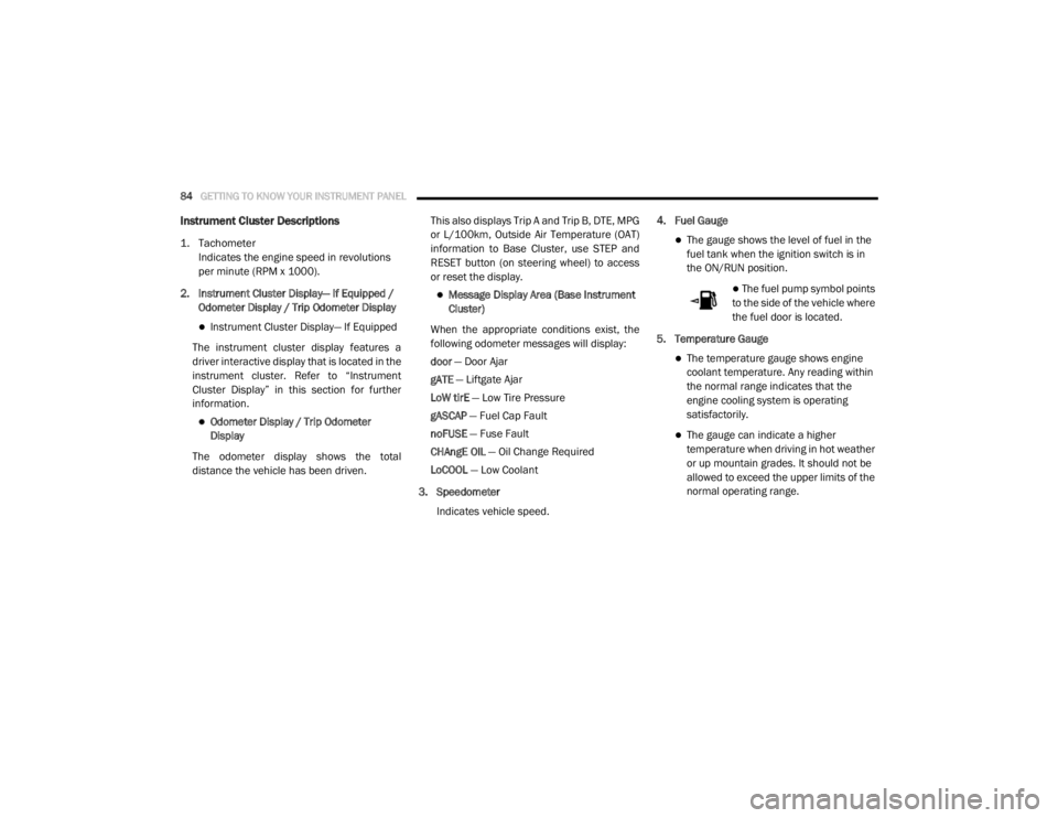
Instrument Cluster Descriptions
1. Tachometer
Indicates the engine speed in revolutions
per minute (RPM x 1000).
2. Instrument Cluster Display— If Equipped / Odometer Display / Trip Odometer Display
Instrument Cluster Display— If Equipped
The instrument cluster display features a
driver interactive display that is located in the
instrument cluster. Refer to “Instrument
Cluster Display” in this section for further
information.
Odometer Display / Trip Odometer
Display
The odometer display shows the total
distance the vehicle has been driven. This also displays Trip A and Trip B, DTE, MPG
or L/100km, Outside Air Temperature (OAT)
information to Base Cluster, use STEP and
RESET button (on steering wheel) to access
or reset the display.
Message Display Area (Base Instrument
Cluster)
When the appropriate conditions exist, the
following odometer messages will display:
door — Door Ajar
gATE — Liftgate Ajar
LoW tirE — Low Tire Pressure
gASCAP — Fuel Cap Fault
noFUSE — Fuse Fault
CHAngE OIL — Oil Change Required
LoCOOL — Low Coolant
3. Speedometer Indicates vehicle speed. 4. Fuel Gauge
The gauge shows the level of fuel in the
fuel tank when the ignition switch is in
the ON/RUN position.
The fuel pump symbol points
to the side of the vehicle where
the fuel door is located.
5. Temperature Gauge
The temperature gauge shows engine
coolant temperature. Any reading within
the normal range indicates that the
engine cooling system is operating
satisfactorily.
The gauge can indicate a higher
temperature when driving in hot weather
or up mountain grades. It should not be
allowed to exceed the upper limits of the
normal operating range.
20_RT_OM_EN_USC_t.book Page 84
Page 100 of 380
98GETTING TO KNOW YOUR INSTRUMENT PANEL
Engine Check/Malfunction Indicator Warning
Light (MIL)
The Engine Check/Malfunction
Indicator Light (MIL) is a part of an
Onboard Diagnostic System called
OBD II that monitors engine and
automatic transmission control systems. This
warning light will illuminate when the ignition is
in the ON/RUN position before engine start. If
the bulb does not come on when turning the
ignition switch from OFF to ON/RUN, have the
condition checked promptly.
Certain conditions, such as a loose or missing
gas cap, poor quality fuel, etc., may illuminate
the light after engine start. The vehicle should
be serviced if the light stays on through several
typical driving styles. In most situations, the
vehicle will drive normally and will not require
towing.
When the engine is running, the MIL may flash
to alert serious conditions that could lead to
immediate loss of power or severe catalytic
converter damage. The vehicle should be
serviced by an authorized dealer as soon as
possible if this occurs.
Tire Pressure Monitoring System (TPMS)
Warning Light
The warning light switches on and a
message is displayed to indicate that
the tire pressure is lower than the
recommended value and/or that slow
pressure loss is occurring. In these cases,
optimal tire duration and fuel consumption may
not be guaranteed.
Should one or more tires be in the condition
mentioned above, the display will show the
indications corresponding to each tire.
WARNING!
A malfunctioning catalytic converter, as
referenced above, can reach higher
temperatures than in normal operating
conditions. This can cause a fire if you drive
slowly or park over flammable substances
such as dry plants, wood, cardboard, etc. This
could result in death or serious injury to the
driver, occupants or others.
CAUTION!
Prolonged driving with the Malfunction
Indicator Light (MIL) on could cause damage
to the vehicle control system. It also could
affect fuel economy and driveability. If the
MIL is flashing, severe catalytic converter
damage and power loss will soon occur.
Immediate service is required.CAUTION!
Do not continue driving with one or more flat
tires as handling may be compromised. Stop
the vehicle, avoiding sharp braking and
steering. If a tire puncture occurs, repair
immediately using the dedicated tire repair
kit and contact an authorized dealer as soon
as possible.
20_RT_OM_EN_USC_t.book Page 98
Page 118 of 380

116SAFETY
(Continued)
NOTE:
When filling warm tires, the tire pressure may
need to be increased up to an additional 4 psi
(28 kPa) above the recommended cold placard
pressure in order to turn the TPMS Warning
Light off. NOTE:
The TPMS is not intended to replace normal
tire care and maintenance, or to provide
warning of a tire failure or condition.
The TPMS should not be used as a tire pres-
sure gauge while adjusting your tire pressure.
Driving on a significantly underinflated tire
causes the tire to overheat and can lead to
tire failure. Underinflation also reduces fuel
efficiency and tire tread life, and may affect
the vehicle’s handling and stopping ability.
The TPMS is not a substitute for proper tire
maintenance, and it is the driver’s responsi -
bility to maintain correct tire pressure using
an accurate tire pressure gauge, even if
underinflation has not reached the level to
trigger illumination of the TPMS Warning
Light.
Seasonal temperature changes will affect
tire pressure, and the TPMS will monitor the
actual tire pressure in the tire.
System Operation
The Tire Pressure Monitoring System (TPMS)
uses wireless technology with wheel
rim-mounted electronic sensors to monitor tire
pressure levels. Sensors, mounted to each
wheel as part of the valve stem, transmit tire
pressure readings to the Receiver Module.
NOTE:
It is particularly important for you to check the
tire pressure in all of your tires regularly and to
maintain the proper pressure.
CAUTION!
The TPMS has been optimized for the orig -
inal equipment tires and wheels. TPMS
pressures and warning have been estab -
lished for the tire size equipped on your
vehicle. Undesirable system operation or
sensor damage may result when using
replacement equipment that is not of the
same size, type, and/or style. The TPM
sensor is not designed for use on after -
market wheels and may contribute to a
poor overall system performance or sensor
damage. Customers are encouraged to use
OEM wheels to assure proper TPM feature
operation.
Using aftermarket tire sealants may cause
the Tire Pressure Monitoring System
(TPMS) sensor to become inoperable. After
using an aftermarket tire sealant it is
recommended that you take your vehicle to
your authorized dealer to have your sensor
function checked.
After inspecting or adjusting the tire pres -
sure always reinstall the valve stem cap.
This will prevent moisture and dirt from
entering the valve stem, which could
damage the TPMS sensor.
CAUTION! (Continued)
20_RT_OM_EN_USC_t.book Page 116
Page 165 of 380
STARTING AND OPERATING163
(Continued)
Cold Weather Operation
(Below –22°F Or −30°C)
To ensure reliable starting at these
temperatures, use of an externally powered
electric engine block heater (available from an
authorized dealer) is recommended.
After Starting — Warming Up The Engine
The idle speed is controlled automatically and it
will decrease as the engine warms up.
If Engine Fails To Start ENGINE BLOCK HEATER — IF EQUIPPED
The engine block heater warms the engine, and
permits quicker starts in cold weather. Connect
the cord to a standard 110-115 Volt AC
electrical outlet with a grounded, three-wire
extension cord.
The engine block heater must be plugged in at
least one hour to have an adequate warming
effect on the engine.
The engine block heater cord is routed under
the hood on the driver's side of the vehicle. It
has a removable cap that is located on the
driver side of the Integrated Power Module.
ENGINE BREAK-IN RECOMMENDATIONS
A long break-in period is not required for the
engine and drivetrain (transmission and axle) in
your vehicle.
Drive moderately during the first 300 miles
(500 km). After the initial 60 miles (100 km),
speeds up to 50 or 55 mph (80 or 90 km/h) are
desirable.
While cruising, brief full-throttle acceleration
within the limits of local traffic laws contributes
to a good break-in. Wide-open throttle
acceleration in low gear can be detrimental and
should be avoided.
WARNING!
Never pour fuel or other flammable liquid
into the throttle body air inlet opening in an
attempt to start the vehicle. This could
result in flash fire causing serious personal
injury.
Do not attempt to push or tow your vehicle
to get it started. Vehicles equipped with an
automatic transmission cannot be started
this way. Unburned fuel could enter the
catalytic converter and once the engine has
started, ignite and damage the converter
and vehicle.
If the vehicle has a discharged battery,
booster cables may be used to obtain a
start from a booster battery or the battery in
another vehicle. This type of start can be
dangerous if done improperly. Refer to
“Jump Starting Procedure” in “In Case Of
Emergency” for further information.
WARNING! (Continued)WARNING!
Remember to disconnect the engine block
heater cord before driving. Damage to the
110-115 Volt electrical cord could cause
electrocution.
5
20_RT_OM_EN_USC_t.book Page 163
Page 174 of 380
172STARTING AND OPERATING
Overdrive Operation
The automatic transmission includes an
electronically controlled Overdrive (SIXTH gear).
The transmission will automatically shift into
Overdrive if the following conditions are
present:
The gear selector is in the DRIVE position.
The transmission fluid has reached an
adequate temperature.
The engine coolant has reached an adequate
temperature.
The vehicle speed is sufficiently high.
The driver is not heavily pressing the
accelerator.
Torque Converter Clutch
A feature designed to improve fuel economy
has been included in the automatic
transmission on your vehicle. A clutch within the
torque converter engages automatically at
calibrated speeds. This may result in a slightly
different feeling or response during normal
operation in the upper gears. When the vehicle
speed drops or during some accelerations, the
clutch automatically disengages. NOTE:
The torque converter clutch will not engage until
the transmission fluid and engine coolant are
warm [usually after 1 to 3 miles (2 to 5 km) of
driving]. Because the engine speed is higher
when the torque converter clutch is not
engaged, it may seem as if the transmission is
not shifting into Overdrive when cold. This is
normal. Using the Electronic Range Select (ERS)
shift control, when the transmission is
sufficiently warm, will demonstrate that the
transmission is able to shift into and out of
Overdrive.
POWER STEERING
The standard Power Steering system will give
you good vehicle response and increased ease
of maneuverability in tight spaces. The system
will provide mechanical steering capability if
power assist is lost.
If for some reason the power assist is
interrupted, it will still be possible to steer your
vehicle. Under these conditions, you will
observe a substantial increase in steering
effort, especially at very low vehicle speeds and
during parking maneuvers.
NOTE:
Increased noise levels at the end of the
steering wheel travel are considered normal
and do not indicate that there is a problem
with the power steering system.
Upon initial start-up in cold weather, the
power steering pump may make noise for a
short amount of time. This is due to the cold,
thick fluid in the steering system. This noise
should be considered normal, and it does not
in any way damage the steering system.
CAUTION!
Prolonged operation of the steering system at
the end of the steering wheel travel will
increase the steering fluid temperature and it
should be avoided when possible. Damage to
the power steering pump may occur.
20_RT_OM_EN_USC_t.book Page 172
Page 183 of 380
STARTING AND OPERATING181
REFUELING THE VEHICLE
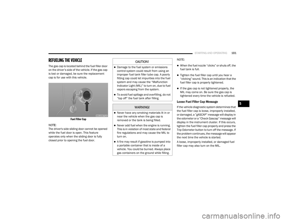
The gas cap is located behind the fuel filler door
on the driver’s side of the vehicle. If the gas cap
is lost or damaged, be sure the replacement
cap is for use with this vehicle.
Fuel Filler Cap
NOTE:
The driver's side sliding door cannot be opened
while the fuel door is open. This feature
operates only when the sliding door is fully
closed prior to opening the fuel door. NOTE:When the fuel nozzle “clicks” or shuts off, the
fuel tank is full.
Tighten the fuel filler cap until you hear a
“clicking” sound. This is an indication that the
fuel filler cap is properly tightened.
If the gas cap is not tightened properly, the
MIL may come on. Be sure the gas cap is
tightened every time the vehicle is refueled.
Loose Fuel Filler Cap Message
If the vehicle diagnostic system determines that
the fuel filler cap is loose, improperly installed,
or damaged, a ”gASCAP” message will display in
the odometer or a “Check Gascap” message will
display in the instrument cluster. If this occurs,
tighten the fuel filler cap properly and press the
Trip Odometer button to turn off the message. If
the problem continues, the message will appear
the next time the vehicle is started.
A loose, improperly installed, or damaged fuel
filler cap may also turn on the MIL.
CAUTION!
Damage to the fuel system or emissions
control system could result from using an
improper fuel tank filler tube cap. A poorly
fitting cap could let impurities into the fuel
system and may cause the “Malfunction
Indicator Light (MIL)” to turn on, due to fuel
vapors escaping from the system.
To avoid fuel spillage and overfilling, do not
“top off” the fuel tank after filling.
WARNING!
Never have any smoking materials lit in or
near the vehicle when the gas cap is
removed or the tank is being filled.
Never add fuel when the engine is running.
This is in violation of most state and federal
fire regulations and may cause the MIL to
turn on.
A fire may result if gasoline is pumped into
a portable container that is inside of a
vehicle. You could be burned. Always place
gas containers on the ground while filling.
5
20_RT_OM_EN_USC_t.book Page 181
Page 184 of 380
182STARTING AND OPERATING
VEHICLE LOADING
Certification Label
As required by National Highway Traffic Safety
Administration regulations, your vehicle has a
certification label affixed to the driver's side
door or pillar.
This label contains the month and year of
manufacture, Gross Vehicle Weight Rating
(GVWR), Gross Axle Weight Rating (GAWR) front
and rear, and Vehicle Identification Number
(VIN). A Month-Day-Hour (MDH) number is
included on this label and indicates the Month,
Day and Hour of manufacture. The bar code
that appears on the bottom of the label is your
VIN.
Gross Vehicle Weight Rating (GVWR)
The GVWR is the total permissible weight of your
vehicle including driver, passengers, vehicle,
options and cargo. The label also specifies
maximum capacities of front and rear axle
systems (GAWR). Total load must be limited so
GVWR and front and rear GAWR are not
exceeded.
Payload
The payload of a vehicle is defined as the
allowable load weight a truck can carry,
including the weight of the driver, all
passengers, options and cargo.
Gross Axle Weight Rating (GAWR)
The GAWR is the maximum permissible load on
the front and rear axles. The load must be
distributed in the cargo area so that the GAWR
of each axle is not exceeded.
Each axle GAWR is determined by the
components in the system with the lowest load
carrying capacity (axle, springs, tires or wheels).
Heavier axles or suspension components
sometimes specified by purchasers for
increased durability does not necessarily
increase the vehicle's GVWR.
Tire Size
The tire size on the Vehicle Certification Label
represents the actual tire size on your vehicle.
Replacement tires must be equal to the load
capacity of this tire size.
Rim Size
This is the rim size that is appropriate for the tire
size listed.
Inflation Pressure
This is the cold tire inflation pressure for your
vehicle for all loading conditions up to full
GAWR.
Curb Weight
The curb weight of a vehicle is defined as the
total weight of the vehicle with all fluids,
including vehicle fuel, at full capacity
conditions, and with no occupants or cargo
loaded into the vehicle. The front and rear curb
weight values are determined by weighing your
vehicle on a commercial scale before any
occupants or cargo are added.
Loading
The actual total weight and the weight of the
front and rear of your vehicle at the ground can
best be determined by weighing it when it is
loaded and ready for operation.
20_RT_OM_EN_USC_t.book Page 182
Page 236 of 380
234SERVICING AND MAINTENANCE
American Petroleum Institute (API) Engine Oil
Identification Symbol
This symbol means that the oil has
been certified by the American
Petroleum Institute (API). The
manufacturer only recommends API
Certified engine oils.
This symbol certifies 0W-20, 5W-20, 0W-30,
5W-30 and 10W-30 engine oils.
Engine Oil Viscosity (SAE Grade) — 3.6L
Engine
Mopar SAE 5W-20 engine oil approved to FCA
Material Standard MS-6395 such as Pennzoil,
Shell Helix or equivalent is recommended for all
operating temperatures. This engine oil
improves low temperature starting and vehicle
fuel economy. The engine oil filler cap also shows the
recommended engine oil viscosity for your
engine. For information on engine oil filler cap
location, refer to the “Engine Compartment”
illustration in this section.
NOTE:
Mopar SAE 5W-30 engine oil approved to FCA
Material Standard MS-6395 such as Pennzoil,
Shell Helix or equivalent may be used when SAE
5W-20 engine oil meeting MS-6395 is not
available.
Lubricants which do not have both the engine
oil certification mark and the correct SAE
viscosity grade number should not be used.
Synthetic Engine Oils
You may use synthetic engine oils provided the
recommended oil quality requirements are met,
and the recommended maintenance intervals
for oil and filter changes are followed.
Synthetic engine oils which do not have both the
engine oil certification mark and the correct SAE
viscosity grade number should not be used.
Materials Added To Engine Oil
The manufacturer strongly recommends
against the addition of any additives (other than
leak detection dyes) to the engine oil. Engine oil
is an engineered product and its performance
may be impaired by supplemental additives.
Disposing Of Used Engine Oil And Oil Filters
Care should be taken in disposing of used
engine oil and oil filters from your vehicle. Used
oil and oil filters, indiscriminately discarded, can
present a problem to the environment. Contact
an authorized dealer, service station or govern
-
mental agency for advice on how and where
used oil and oil filters can be safely discarded in
your area.
Engine Oil Filter
The engine oil filter should be replaced with a
new filter at every engine oil change.
Engine Oil Filter Selection
This manufacturer's engines have a full-flow
type disposable oil filter. Use a filter of this type
for replacement. The quality of replacement
filters varies considerably. Only high quality
filters should be used to assure most efficient
service. Mopar engine oil filters are high quality
oil filters and are recommended.
CAUTION!
Do not use chemical flushes in your engine oil
as the chemicals can damage your engine.
Such damage is not covered by the New
Vehicle Limited Warranty.
20_RT_OM_EN_USC_t.book Page 234