display DODGE HORNET 2023 User Guide
[x] Cancel search | Manufacturer: DODGE, Model Year: 2023, Model line: HORNET, Model: DODGE HORNET 2023Pages: 288, PDF Size: 14.2 MB
Page 51 of 288
GETTING TO KNOW YOUR VEHICLE49
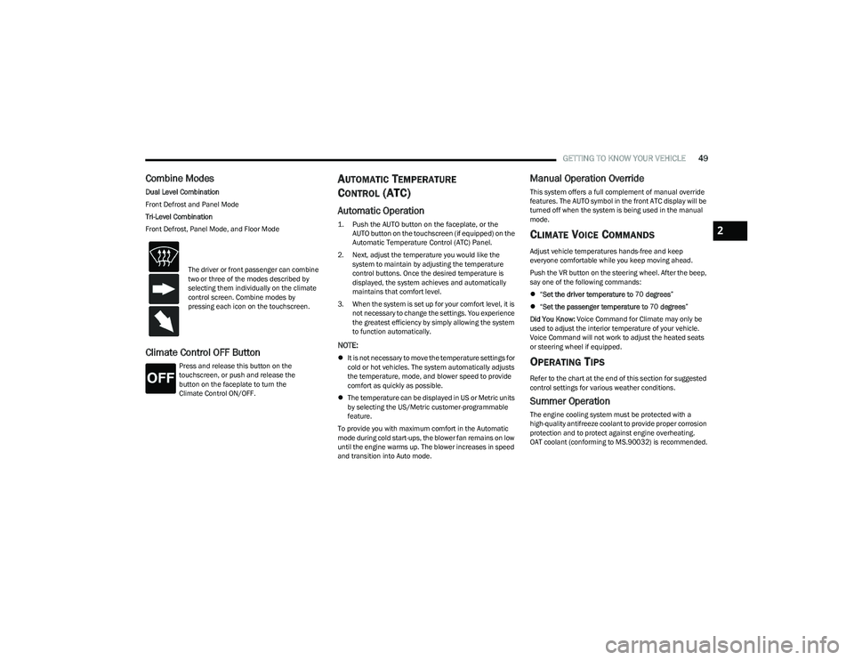
Combine Modes
Dual Level Combination
Front Defrost and Panel Mode
Tri-Level Combination
Front Defrost, Panel Mode, and Floor Mode
Climate Control OFF Button
Press and release this button on the
touchscreen, or push and release the
button on the faceplate to turn the
Climate Control ON/OFF.
AUTOMATIC TEMPERATURE
CONTROL (ATC)
Automatic Operation
1. Push the AUTO button on the faceplate, or the
AUTO button on the touchscreen (if equipped) on the
Automatic Temperature Control (ATC) Panel.
2. Next, adjust the temperature you would like the system to maintain by adjusting the temperature
control buttons. Once the desired temperature is
displayed, the system achieves and automatically
maintains that comfort level.
3. When the system is set up for your comfort level, it is not necessary to change the settings. You experience
the greatest efficiency by simply allowing the system
to function automatically.
NOTE:
It is not necessary to move the temperature settings for
cold or hot vehicles. The system automatically adjusts
the temperature, mode, and blower speed to provide
comfort as quickly as possible.
The temperature can be displayed in US or Metric units
by selecting the US/Metric customer-programmable
feature.
To provide you with maximum comfort in the Automatic
mode during cold start-ups, the blower fan remains on low
until the engine warms up. The blower increases in speed
and transition into Auto mode.
Manual Operation Override
This system offers a full complement of manual override
features. The AUTO symbol in the front ATC display will be
turned off when the system is being used in the manual
mode.
CLIMATE VOICE COMMANDS
Adjust vehicle temperatures hands-free and keep
everyone comfortable while you keep moving ahead.
Push the VR button on the steering wheel. After the beep,
say one of the following commands:
“Set the driver temperature to 70 degrees ”
“Set the passenger temperature to 70 degrees ”
Did You Know: Voice Command for Climate may only be
used to adjust the interior temperature of your vehicle.
Voice Command will not work to adjust the heated seats
or steering wheel if equipped.
OPERATING TIPS
Refer to the chart at the end of this section for suggested
control settings for various weather conditions.
Summer Operation
The engine cooling system must be protected with a
high-quality antifreeze coolant to provide proper corrosion
protection and to protect against engine overheating.
OAT coolant (conforming to MS.90032) is recommended.
The driver or front passenger can combine
two or three of the modes described by
selecting them individually on the climate
control screen. Combine modes by
pressing each icon on the touchscreen.
2
23_GG_OM_EN_USC_t.book Page 49
Page 54 of 288
52GETTING TO KNOW YOUR VEHICLE
By using a USB cable to connect an external device:
The device can be played on the vehicle’s sound
system, providing the artist, track title, and album infor -
mation on the radio display.
NOTE:Depending on track configuration, track information may
not be present on the radio display.
The device can be controlled using the radio buttons to
play, and browse the contents of the device.
The audio device battery charges when plugged into
the USB port.
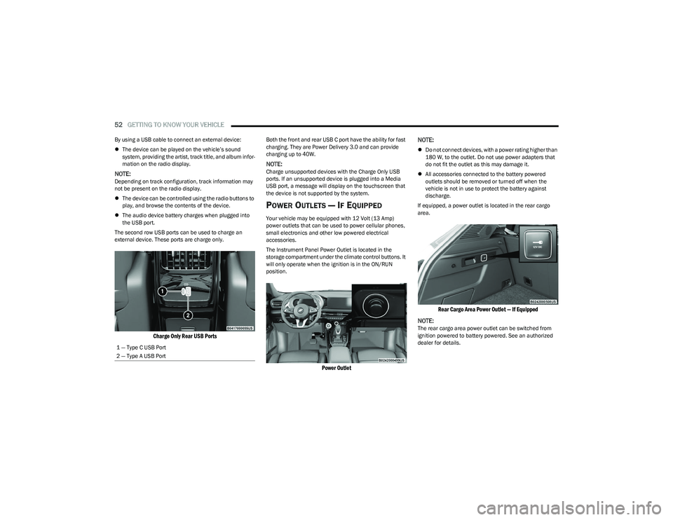
The second row USB ports can be used to charge an
external device. These ports are charge only.
Charge Only Rear USB Ports
Both the front and rear USB C port have the ability for fast
charging. They are Power Delivery 3.0 and can provide
charging up to 40W.
NOTE:Charge unsupported devices with the Charge Only USB
ports. If an unsupported device is plugged into a Media
USB port, a message will display on the touchscreen that
the device is not supported by the system.
POWER OUTLETS — IF EQUIPPED
Your vehicle may be equipped with 12 Volt (13 Amp)
power outlets that can be used to power cellular phones,
small electronics and other low powered electrical
accessories.
The Instrument Panel Power Outlet is located in the
storage compartment under the climate control buttons. It
will only operate when the ignition is in the ON/RUN
position.
Power Outlet
NOTE:
Do not connect devices, with a power rating higher than
180 W, to the outlet. Do not use power adapters that
do not fit the outlet as this may damage it.
All accessories connected to the battery powered
outlets should be removed or turned off when the
vehicle is not in use to protect the battery against
discharge.
If equipped, a power outlet is located in the rear cargo
area.
Rear Cargo Area Power Outlet — If Equipped
NOTE:
The rear cargo area power outlet can be switched from
ignition powered to battery powered. See an authorized
dealer for details.
1 — Type C USB Port
2 — Type A USB Port
23_GG_OM_EN_USC_t.book Page 52
Page 56 of 288
54GETTING TO KNOW YOUR VEHICLE
The wireless charging pad is equipped with an anti-slip
mat to hold your mobile phone in place, and an LED
indicator light.
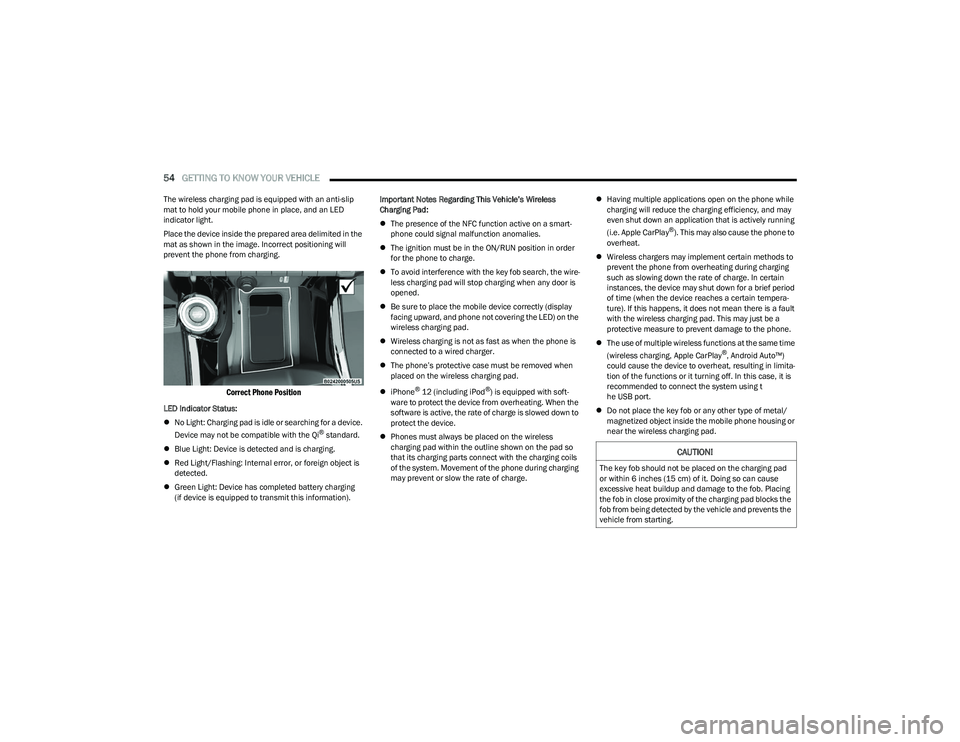
Place the device inside the prepared area delimited in the
mat as shown in the image. Incorrect positioning will
prevent the phone from charging.
Correct Phone Position
LED Indicator Status:
No Light: Charging pad is idle or searching for a device.
Device may not be compatible with the Qi
® standard.
Blue Light: Device is detected and is charging.
Red Light/Flashing: Internal error, or foreign object is
detected.
Green Light: Device has completed battery charging
(if device is equipped to transmit this information). Important Notes Regarding This Vehicle’s Wireless
Charging Pad:
The presence of the NFC function active on a smart -
phone could signal malfunction anomalies.
The ignition must be in the ON/RUN position in order
for the phone to charge.
To avoid interference with the key fob search, the wire -
less charging pad will stop charging when any door is
opened.
Be sure to place the mobile device correctly (display
facing upward, and phone not covering the LED) on the
wireless charging pad.
Wireless charging is not as fast as when the phone is
connected to a wired charger.
The phone’s protective case must be removed when
placed on the wireless charging pad.
iPhone
® 12 (including iPod®) is equipped with soft -
ware to protect the device from overheating. When the
software is active, the rate of charge is slowed down to
protect the device.
Phones must always be placed on the wireless
charging pad within the outline shown on the pad so
that its charging parts connect with the charging coils
of the system. Movement of the phone during charging
may prevent or slow the rate of charge.
Having multiple applications open on the phone while
charging will reduce the charging efficiency, and may
even shut down an application that is actively running
(i.e. Apple CarPlay
®). This may also cause the phone to
overheat.
Wireless chargers may implement certain methods to
prevent the phone from overheating during charging
such as slowing down the rate of charge. In certain
instances, the device may shut down for a brief period
of time (when the device reaches a certain tempera -
ture). If this happens, it does not mean there is a fault
with the wireless charging pad. This may just be a
protective measure to prevent damage to the phone.
The use of multiple wireless functions at the same time
(wireless charging, Apple CarPlay
®, Android Auto™)
could cause the device to overheat, resulting in limita -
tion of the functions or it turning off. In this case, it is
recommended to connect the system using t
he USB port.
Do not place the key fob or any other type of metal/
magnetized object inside the mobile phone housing or
near the wireless charging pad.
CAUTION!
The key fob should not be placed on the charging pad
or within 6 inches (15 cm) of it. Doing so can cause
excessive heat buildup and damage to the fob. Placing
the fob in close proximity of the charging pad blocks the
fob from being detected by the vehicle and prevents the
vehicle from starting.
23_GG_OM_EN_USC_t.book Page 54
Page 68 of 288
66GETTING TO KNOW YOUR INSTRUMENT PANEL
INSTRUMENT CLUSTER DESCRIPTIONS
Use this QR code to access your digital
experience.
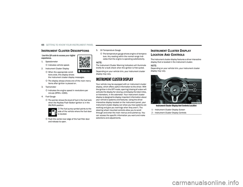
1. Speedometer
Indicates vehicle speed.
2. Instrument Cluster Display When the appropriate condi -
tions exist, this display shows
the instrument cluster display messages.
The display always shows one of the main menu
items after ignition is placed on.
3. Tachometer Indicates the engine speed in revolutions per
minute (RPM x 1000).
4. Fuel Gauge The pointer shows the level of fuel in the fuel tank
when the Keyless Push Button Ignition is in the
ON/RUN position.
The fuel pump symbol points to the
side of the vehicle where the fuel door
is located.
Push the center-rear edge of the fuel filler door
and release to open. 5. Oil Temperature Gauge
The temperature gauge shows engine oil tempera -
ture. Any reading within the normal range indi -
cates that the engine is operating satisfactorily.
NOTE:The Instrument Cluster Warning Indicators will illuminate
briefly for a bulb check when the ignition is first cycled.
Depending on your vehicle trim, your instrument cluster
display may vary.
INSTRUMENT CLUSTER DISPLAY
Your vehicle may be equipped with an instrument cluster
display, which offers useful information to the driver. With
the ignition in the OFF mode, opening/closing of a door will
activate the display for viewing, and display the total miles,
or kilometers, in the odometer. Your instrument cluster
display is designed to display important information about
your vehicle’s systems and features. Using the driver
interactive display located on the instrument panel, your
instrument cluster display can show you how systems are
working and give you warnings when they aren’t. The
steering wheel mounted controls allow you to scroll
through and enter the main menus and submenus. You
can access the specific information you want and make
selections and adjustments.
INSTRUMENT CLUSTER DISPLAY
L
OCATION AND CONTROLS
The instrument cluster display features a driver interactive
display that is located in the instrument cluster.
NOTE:Depending on your vehicle trim, your instrument cluster
display may vary.
Instrument Cluster Display And Controls Location
1 – Instrument Cluster Display Screen
2 – Instrument Cluster Display Controls
23_GG_OM_EN_USC_t.book Page 66
Page 69 of 288
GETTING TO KNOW YOUR INSTRUMENT PANEL67
The systems allow the driver to select information by
pushing the following buttons mounted on the steering
wheel:
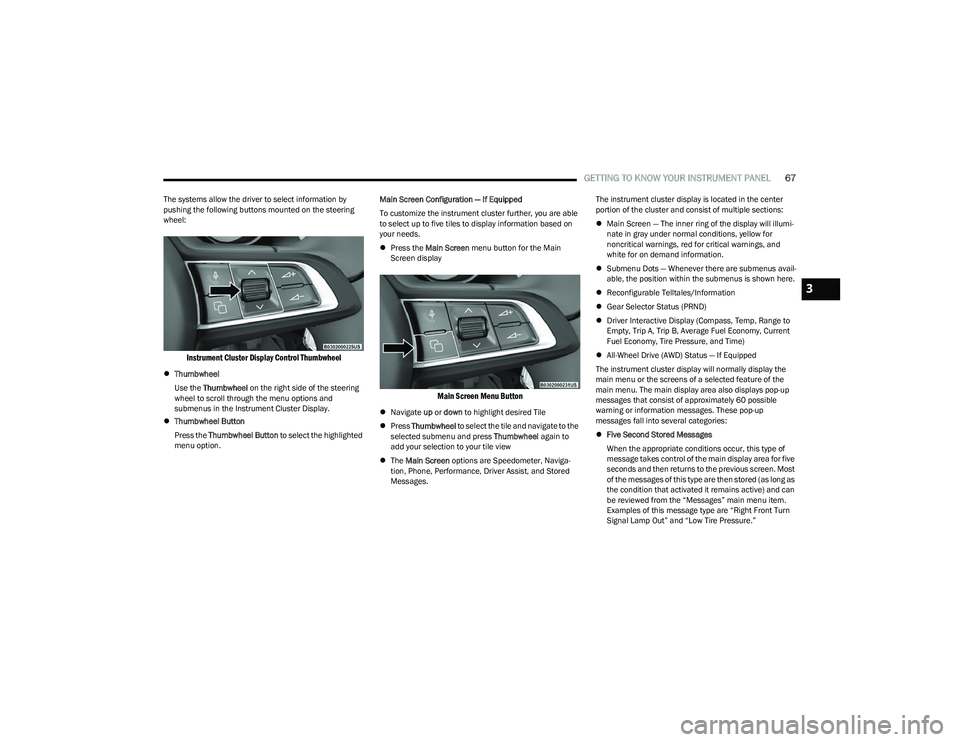
Instrument Cluster Display Control Thumbwheel
Thumbwheel
Use the Thumbwheel on the right side of the steering
wheel to scroll through the menu options and
submenus in the Instrument Cluster Display.
Thumbwheel Button
Press the Thumbwheel Button to select the highlighted
menu option. Main Screen Configuration — If Equipped
To customize the instrument cluster further, you are able
to select up to five tiles to display information based on
your needs.
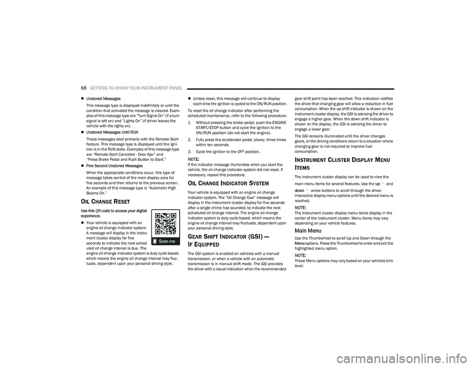
Press the Main Screen menu button for the Main
Screen display
Main Screen Menu Button
Navigate up or down to highlight desired Tile
Press Thumbwheel to select the tile and navigate to the
selected submenu and press Thumbwheel again to
add your selection to your tile view
The Main Screen options are Speedometer, Naviga -
tion, Phone, Performance, Driver Assist, and Stored
Messages. The instrument cluster display is located in the center
portion of the cluster and consist of multiple sections:
Main Screen — The inner ring of the display will illumi -
nate in gray under normal conditions, yellow for
noncritical warnings, red for critical warnings, and
white for on demand information.
Submenu Dots — Whenever there are submenus avail -
able, the position within the submenus is shown here.
Reconfigurable Telltales/Information
Gear Selector Status (PRND)
Driver Interactive Display (Compass, Temp, Range to
Empty, Trip A, Trip B, Average Fuel Economy, Current
Fuel Economy, Tire Pressure, and Time)
All-Wheel Drive (AWD) Status — If Equipped
The instrument cluster display will normally display the
main menu or the screens of a selected feature of the
main menu. The main display area also displays pop-up
messages that consist of approximately 60 possible
warning or information messages. These pop-up
messages fall into several categories:
Five Second Stored Messages
When the appropriate conditions occur, this type of
message takes control of the main display area for five
seconds and then returns to the previous screen. Most
of the messages of this type are then stored (as long as
the condition that activated it remains active) and can
be reviewed from the “Messages” main menu item.
Examples of this message type are “Right Front Turn
Signal Lamp Out” and “Low Tire Pressure.”
3
23_GG_OM_EN_USC_t.book Page 67
Page 70 of 288
68GETTING TO KNOW YOUR INSTRUMENT PANEL
Unstored Messages
This message type is displayed indefinitely or until the
condition that activated the message is cleared. Exam -
ples of this message type are “Turn Signal On” (if a turn
signal is left on) and “Lights On” (if driver leaves the
vehicle with the lights on).
Unstored Messages Until RUN
These messages deal primarily with the Remote Start
feature. This message type is displayed until the igni -
tion is in the RUN state. Examples of this message type
are “Remote Start Canceled - Door Ajar” and
“Press Brake Pedal and Push Button to Start.”
Five Second Unstored Messages
When the appropriate conditions occur, this type of
message takes control of the main display area for
five seconds and then returns to the previous screen.
An example of this message type is “Automatic High
Beams On.”
OIL CHANGE RESET
Use this QR code to access your digital
experience.
Your vehicle is equipped with an
engine oil change indicator system.
A message will display in the instru -
ment cluster display for five
seconds to indicate the next sched -
uled oil change interval is due. The
engine oil change indicator system is duty cycle based,
which means the engine oil change interval may fluc -
tuate, dependent upon your personal driving style.
Unless reset, this message will continue to display
each time the ignition is cycled to the ON/RUN position.
To reset the oil change indicator after performing the
scheduled maintenance, refer to the following procedure:
1. Without pressing the brake pedal, push the ENGINE START/STOP button and cycle the ignition to the
ON/RUN position (do not start the engine).
2. Fully press the accelerator pedal, slowly, three times within ten seconds.
3. Cycle the ignition to the OFF position.
NOTE:If the indicator message illuminates when you start the
vehicle, the oil change indicator system did not reset. If
necessary, repeat this procedure.
OIL CHANGE INDICATOR SYSTEM
Your vehicle is equipped with an engine oil change
indicator system. The “Oil Change Due” message will
display in the instrument cluster display for five seconds
after a single chime has sounded, to indicate the next
scheduled oil change interval. The engine oil change
indicator system is duty cycle based, which means the
engine oil change interval may fluctuate, dependent upon
your personal driving style.
GEAR SHIFT INDICATOR (GSI) —
I
F EQUIPPED
The GSI system is enabled on vehicles with a manual
transmission, or when a vehicle with an automatic
transmission is in manual shift mode. The GSI provides
the driver with a visual indication when the recommended gear shift point has been reached. This indication notifies
the driver that changing gear will allow a reduction in fuel
consumption. When the up shift indicator is shown on the
instrument cluster display, the GSI is advising the driver to
engage a higher gear. When the down shift indicator is
shown on the display, the GSI is advising the driver to
engage a lower gear.
The GSI remains illuminated until the driver changes
gears, or the driving conditions return to a situation where
changing gear is not required to improve fuel
consumption.
INSTRUMENT CLUSTER DISPLAY MENU
I
TEMS
The instrument cluster display can be used to view the
main menu items for several features. Use the up and
down arrow buttons to scroll through the driver
interactive display menu options until the desired menu is
reached.
NOTE:The instrument cluster display menu items display in the
center of the instrument cluster. Menu items may vary
depending on your vehicle features.
Main Menu
Use the Thumbwheel to scroll Up and Down through the
Menu options. Press the Thumbwheel to enter and exit the
highlighted menu option.
NOTE:These Menu options may vary based on your vehicles trim
level.
23_GG_OM_EN_USC_t.book Page 68
Page 71 of 288
GETTING TO KNOW YOUR INSTRUMENT PANEL69
SPEEDOMETER
The Speedometer menu options may consist of the
following:
Digital speed and speed unit (MPH or km/h)
Gear Shift Indicator (GSI)
Gear
Drive mode name
The speed units can be changed from MPH to km/h by
pressing the Thumbwheel.
NAVIGATION — IF EQUIPPED
Turn the Thumbwheel up or down to increase or decrease
the zoom on this screen. Press the Thumbwheel to go
back to the initial frame. The zoom level is automatically
reset to the factory settings whenever the engine is
restarted.
The following information is shown:
Direction Indicators
Distance to next change of direction (in miles or kilome -
ters, depending on instrument panel settings)
Suggested lanes
Address of the road to be followed after the change of
direction Press and hold the Thumbwheel to disable the indications
in the right-hand ring for the current navigation. If a
predicted route is selected, the route shall start without
further confirmation.
NOTE:During projection modes (Apple CarPlay® or
Android Auto™) the native map is not available.
PHONE
This menu displays the current status of a phone
connected to the vehicle via Bluetooth®. The System
supports up to two phones connected at the same time.
Information available in cluster depends on which phone
is dynamically selected by the user in each moment (i.e.
the phone in focus), to enter and select one of the phone
connected user should press Thumbwheel
If no phone is connected, the menu will not function when
the
OK button is pushed. Otherwise, if a phone is
connected, push the OK button to enter the menu.
The following items will display:
Recent calls: displays a list of the last 10 calls.
SMS reader: displays the last 10 text messages and if
they are read or unread.
Favorite numbers: displays a maximum of 10 favorite
numbers.
PERFORMANCE
Performance page content automatically changes
according to the selected drive mode.
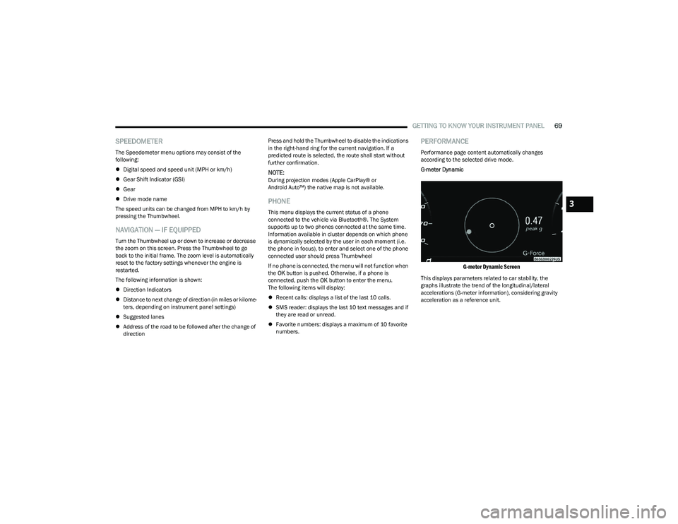
G-meter Dynamic
G-meter Dynamic Screen
This displays parameters related to car stability, the
graphs illustrate the trend of the longitudinal/lateral
accelerations (G-meter information), considering gravity
acceleration as a reference unit.
3
23_GG_OM_EN_USC_t.book Page 69
Page 72 of 288
70GETTING TO KNOW YOUR INSTRUMENT PANEL
DRIVER ASSIST
The instrument cluster display displays the current
Adaptive Cruise Control (ACC) and Lane Keep Assist (LKA)
system settings. The information displayed depends on
ACC system status.
The Instrument Cluster Display shows the status and
settings of the driving assistance Adaptive Cruise Control,
Lane Keep Assist and Active Driving Assist systems. Any
instant notifications are displayed via a pop-up screen.
The instrument cluster display displays the current LKA
system settings. The information displayed depends on
Lane Keep Assist system status and the conditions that
need to be met
Úpage 113.
STORED MESSAGES
Turn the Thumbwheel up and down until the Stored
Messages menu option is highlighted. Press the
Thumbwheel to enter and exit the Stored Messages.
Messages shown on the display via popup screens are
stored as long as they remain valid. You can view them
later in the central area of the “Messages” screen.
If multiple messages are present:
Press the Thumbwheel to access the message list.
Scroll through the messages by turning the Thumb -
wheel up or down. The presence or previous or next
message is indicated by gray dots.
BATTERY SAVER ON/BATTERY SAVER
M
ODE MESSAGE — ELECTRICAL LOAD
R
EDUCTION ACTIONS — IF EQUIPPED
This vehicle is equipped with an Intelligent Battery Sensor
(IBS) to perform additional monitoring of the electrical
system and status of the vehicle battery.
In cases when the IBS detects charging system failure, or
the vehicle battery conditions are deteriorating, electrical
load reduction actions will take place to extend the driving
time and distance of the vehicle. This is done by reducing
power to or turning off non-essential electrical loads.
Load reduction is only active when the engine is running.
It will display a message if there is a risk of battery
depletion to the point where the vehicle may stall due to
lack of electrical supply, or will not restart after the current
drive cycle.
These messages indicate the vehicle battery has a low
state of charge and continues to lose electrical charge at
a rate that the charging system cannot sustain.
NOTE:
The charging system is independent from load reduc -
tion. The charging system performs a diagnostic on the
charging system continuously.
If the Battery Charge Warning Light is on it may indicate
a problem with the charging system
Úpage 72. The electrical loads that may be switched off (if equipped),
and vehicle functions which can be effected by load
reduction:
Heated Seat/Vented Seats/Heated Wheel
Heated/Cooled Cup Holders — If Equipped
Rear Defroster And Heated Mirrors
HVAC System
150W Power Inverter System
Audio and Telematics System
Loss of the battery charge may indicate one or more of the
following conditions:
The charging system cannot deliver enough electrical
power to the vehicle system because the electrical
loads are larger than the capability of charging system.
The charging system is still functioning properly.
Turning on all possible vehicle electrical loads (e.g.
HVAC to max settings, exterior and interior lights, over -
loaded power outlets +12 Volts, 150W, USB ports)
during certain driving conditions (city driving, towing,
frequent stopping).
Installing options like additional lights, upfitter elec -
trical accessories, audio systems, alarms and similar
devices.
Unusual driving cycles (short trips separated by long
parking periods).
The vehicle was parked for an extended period of time
(weeks, months).
23_GG_OM_EN_USC_t.book Page 70
Page 73 of 288
GETTING TO KNOW YOUR INSTRUMENT PANEL71
The battery was recently replaced and was not charged
completely.
The battery was discharged by an electrical load left on
when the vehicle was parked.
The battery was used for an extended period with the
engine not running to supply radio, lights, chargers,
+12 Volts portable appliances like vacuum cleaners,
game consoles and similar devices.
What to do when an electrical load reduction action
message is present (“Battery Saver On” or
“Battery Saver Mode”)
During a trip:
Reduce power to unnecessary loads if possible:
Turn off redundant lights (interior or exterior)
Check what may be plugged into power outlets
+12 Volts, 150W, USB ports
Check HVAC settings (blower, temperature)
Check the audio settings (volume)
After a trip:
Check if any aftermarket equipment was installed
(additional lights, upfitter electrical accessories,
audio systems, alarms) and review specifications if any
(load and Ignition Off Draw currents).
Evaluate the latest driving cycles (distance, driving
time and parking time).
The vehicle should have service performed if the
message is still present during consecutive trips and
the evaluation of the vehicle and driving pattern did not
help to identify the cause.WARNING LIGHTS AND MESSAGES
The warning/indicator lights will illuminate in the
instrument panel together with a dedicated message and/
or acoustic signal when applicable. These indications are
indicative and precautionary and as such must not be
considered as exhaustive and/or alternative to the
information contained in the Owner’s Manual, which you
are advised to read carefully in all cases. Always refer to
the information in this chapter in the event of a failure
indication. All active telltales will display first if applicable.
The system check menu may appear different based upon
equipment options and current vehicle status. Some
telltales are optional and may not appear.
RED WARNING LIGHTS
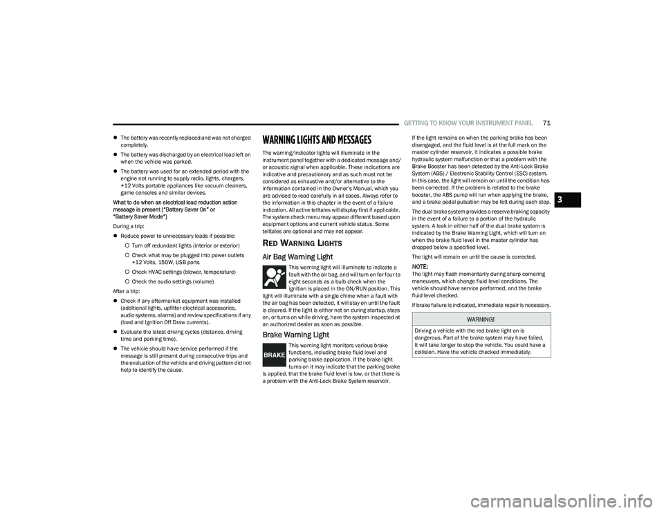
Air Bag Warning Light
This warning light will illuminate to indicate a
fault with the air bag, and will turn on for four to
eight seconds as a bulb check when the
ignition is placed in the ON/RUN position. This
light will illuminate with a single chime when a fault with
the air bag has been detected, it will stay on until the fault
is cleared. If the light is either not on during startup, stays
on, or turns on while driving, have the system inspected at
an authorized dealer as soon as possible.
Brake Warning Light
This warning light monitors various brake
functions, including brake fluid level and
parking brake application. If the brake light
turns on it may indicate that the parking brake
is applied, that the brake fluid level is low, or that there is
a problem with the Anti-Lock Brake System reservoir. If the light remains on when the parking brake has been
disengaged, and the fluid level is at the full mark on the
master cylinder reservoir, it indicates a possible brake
hydraulic system malfunction or that a problem with the
Brake Booster has been detected by the Anti-Lock Brake
System (ABS) / Electronic Stability Control (ESC) system.
In this case, the light will remain on until the condition has
been corrected. If the problem is related to the brake
booster, the ABS pump will run when applying the brake,
and a brake pedal pulsation may be felt during each stop.
The dual brake system provides a reserve braking capacity
in the event of a failure to a portion of the hydraulic
system. A leak in either half of the dual brake system is
indicated by the Brake Warning Light, which will turn on
when the brake fluid level in the master cylinder has
dropped below a specified level.
The light will remain on until the cause is corrected.
NOTE:The light may flash momentarily during sharp cornering
maneuvers, which change fluid level conditions. The
vehicle should have service performed, and the brake
fluid level checked.
If brake failure is indicated, immediate repair is necessary.
WARNING!
Driving a vehicle with the red brake light on is
dangerous. Part of the brake system may have failed.
It will take longer to stop the vehicle. You could have a
collision. Have the vehicle checked immediately.
3
23_GG_OM_EN_USC_t.book Page 71
Page 74 of 288
72GETTING TO KNOW YOUR INSTRUMENT PANEL
Vehicles equipped with the Anti-Lock Brake System (ABS)
are also equipped with Electronic Brake Force Distribution
(EBD). In the event of an EBD failure, the Brake Warning
Light will turn on along with the ABS Light. Immediate
repair to the ABS system is required.
Operation of the Brake Warning Light can be checked by
turning the ignition switch from the OFF position to the
ON/RUN position. The light should illuminate for
approximately two seconds. The light should then turn off
unless the parking brake is applied or a brake fault is
detected. If the light does not illuminate, have the light
inspected by an authorized dealer.
The light also will turn on when the parking brake is
applied with the ignition switch in the ON/RUN position.
NOTE:This light shows only that the parking brake is applied.
It does not show the degree of brake application.
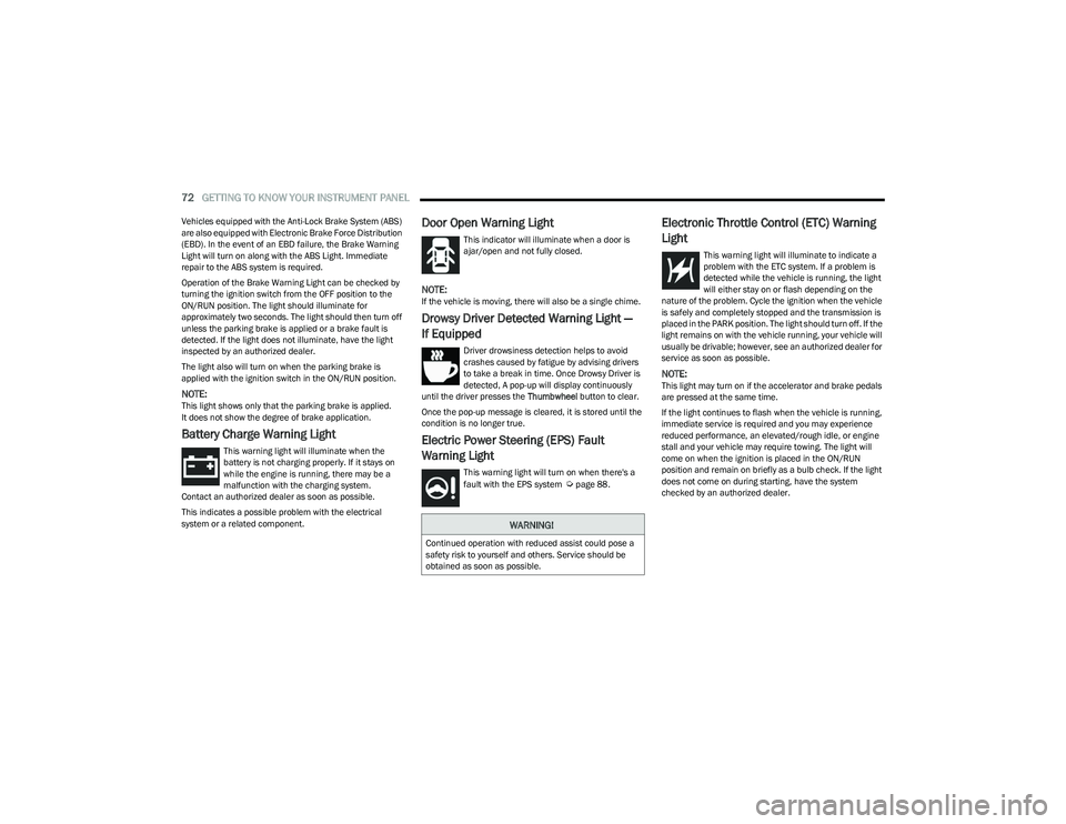
Battery Charge Warning Light
This warning light will illuminate when the
battery is not charging properly. If it stays on
while the engine is running, there may be a
malfunction with the charging system.
Contact an authorized dealer as soon as possible.
This indicates a possible problem with the electrical
system or a related component.
Door Open Warning Light
This indicator will illuminate when a door is
ajar/open and not fully closed.
NOTE:If the vehicle is moving, there will also be a single chime.
Drowsy Driver Detected Warning Light —
If Equipped
Driver drowsiness detection helps to avoid
crashes caused by fatigue by advising drivers
to take a break in time. Once Drowsy Driver is
detected, A pop-up will display continuously
until the driver presses the Thumbwheel button to clear.
Once the pop-up message is cleared, it is stored until the
condition is no longer true.
Electric Power Steering (EPS) Fault
Warning Light
This warning light will turn on when there's a
fault with the EPS system Úpage 88.
Electronic Throttle Control (ETC) Warning
Light
This warning light will illuminate to indicate a
problem with the ETC system. If a problem is
detected while the vehicle is running, the light
will either stay on or flash depending on the
nature of the problem. Cycle the ignition when the vehicle
is safely and completely stopped and the transmission is
placed in the PARK position. The light should turn off. If the
light remains on with the vehicle running, your vehicle will
usually be drivable; however, see an authorized dealer for
service as soon as possible.
NOTE:This light may turn on if the accelerator and brake pedals
are pressed at the same time.
If the light continues to flash when the vehicle is running,
immediate service is required and you may experience
reduced performance, an elevated/rough idle, or engine
stall and your vehicle may require towing. The light will
come on when the ignition is placed in the ON/RUN
position and remain on briefly as a bulb check. If the light
does not come on during starting, have the system
checked by an authorized dealer.
WARNING!
Continued operation with reduced assist could pose a
safety risk to yourself and others. Service should be
obtained as soon as possible.
23_GG_OM_EN_USC_t.book Page 72