display DODGE HORNET 2023 Manual Online
[x] Cancel search | Manufacturer: DODGE, Model Year: 2023, Model line: HORNET, Model: DODGE HORNET 2023Pages: 288, PDF Size: 14.2 MB
Page 165 of 288
SAFETY163
If a Forward Collision Warning with Mitigation event begins
at a speed below 39 mph (62 km/h), the system may
provide the maximum braking possible to mitigate the
potential forward collision. If the Forward Collision
Warning with Mitigation event stops the vehicle
completely, the system will hold the vehicle at standstill for
two seconds and then release the brakes.
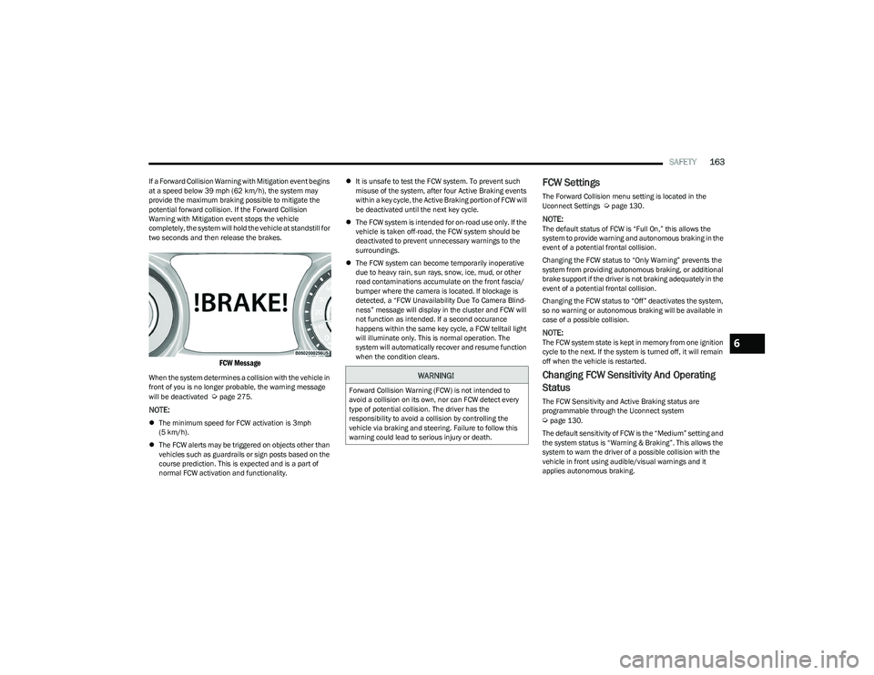
FCW Message
When the system determines a collision with the vehicle in
front of you is no longer probable, the warning message
will be deactivated
Úpage 275.
NOTE:
The minimum speed for FCW activation is 3mph
(5 km/h).
The FCW alerts may be triggered on objects other than
vehicles such as guardrails or sign posts based on the
course prediction. This is expected and is a part of
normal FCW activation and functionality.
It is unsafe to test the FCW system. To prevent such
misuse of the system, after four Active Braking events
within a key cycle, the Active Braking portion of FCW will
be deactivated until the next key cycle.
The FCW system is intended for on-road use only. If the
vehicle is taken off-road, the FCW system should be
deactivated to prevent unnecessary warnings to the
surroundings.
The FCW system can become temporarily inoperative
due to heavy rain, sun rays, snow, ice, mud, or other
road contaminations accumulate on the front fascia/
bumper where the camera is located. If blockage is
detected, a “FCW Unavailability Due To Camera Blind -
ness” message will display in the cluster and FCW will
not function as intended. If a second occurance
happens within the same key cycle, a FCW telltail light
will illuminate only. This is normal operation. The
system will automatically recover and resume function
when the condition clears.
FCW Settings
The Forward Collision menu setting is located in the
Uconnect Settings Úpage 130.
NOTE:The default status of FCW is “Full On,” this allows the
system to provide warning and autonomous braking in the
event of a potential frontal collision.
Changing the FCW status to “Only Warning” prevents the
system from providing autonomous braking, or additional
brake support if the driver is not braking adequately in the
event of a potential frontal collision.
Changing the FCW status to “Off” deactivates the system,
so no warning or autonomous braking will be available in
case of a possible collision.
NOTE:The FCW system state is kept in memory from one ignition
cycle to the next. If the system is turned off, it will remain
off when the vehicle is restarted.
Changing FCW Sensitivity And Operating
Status
The FCW Sensitivity and Active Braking status are
programmable through the Uconnect system
Úpage 130.
The default sensitivity of FCW is the “Medium” setting and
the system status is “Warning & Braking”. This allows the
system to warn the driver of a possible collision with the
vehicle in front using audible/visual warnings and it
applies autonomous braking.
WARNING!
Forward Collision Warning (FCW) is not intended to
avoid a collision on its own, nor can FCW detect every
type of potential collision. The driver has the
responsibility to avoid a collision by controlling the
vehicle via braking and steering. Failure to follow this
warning could lead to serious injury or death.
6
23_GG_OM_EN_USC_t.book Page 163
Page 166 of 288
164SAFETY
By changing the FCW status setting to "Far", the system
provides possible collision warnings on objects farther
away. This results in earlier warnings and provides the
most reaction time to avoid possible collisions.
NOTE:The “Far” setting may result in a greater number of FCW
possible collision warnings experienced.
By changing the FCW status setting to "Near", the system
provides possible collision warnings on objects closer to
the vehicle. This results in later warnings and provides
less reaction time than the "Far" and "Medium" settings,
which allows for a more dynamic driving experience.
NOTE:The “Near” setting may result in a lesser number of FCW
possible collision warnings experienced.
NOTE:
Changing the FCW status to “Only Warning” prevents
the system from providing limited active braking, or
additional brake support if the driver is not braking
adequately in the event of a potential frontal collision,
but maintains the audible and visual warnings.
Changing the FCW status to “Off” prevents the system
from providing autonomous braking, or additional
brake support if the driver is not braking adequately in
the event of a potential frontal collision.
The system will retain the last setting selected by the
driver after ignition shut down.
FCW may not react to irrelevant objects such as over -
head objects, ground reflections, objects not in the
path of the vehicle, stationary objects that are far away,
oncoming traffic, or leading vehicles with the same or
higher rates of speed.
FCW will be disabled like ACC, with the unavailable
screens.
FCW Limited Warning
If the instrument cluster display reads “FCW Limited
Functionality” or “FCW Limited Functionality Clean Front
Windshield” momentarily, there may be a condition that
limits FCW functionality. Although the vehicle is still
driveable under normal conditions, the active braking may
not be fully available. Once the condition that limited the
system performance is no longer present, the system will
return to its full performance state. If the problem persists,
see an authorized dealer.
Service FCW Warning
If the system turns off, and the instrument cluster display
reads “FCW Unavailable Service Required”, there is an
internal system fault. Although the vehicle is still driveable
under normal conditions, have the system checked by an
authorized dealer.
Pedestrian Emergency Braking (PEB) —
If Equipped
PEB is a subsystem of the Forward Collision Warning (FCW)
system which provides the driver with audible warnings
and visual warnings, in the instrument cluster display. It
may apply limited automatic braking when it detects a
potential frontal collision with a pedestrian/cyclist.
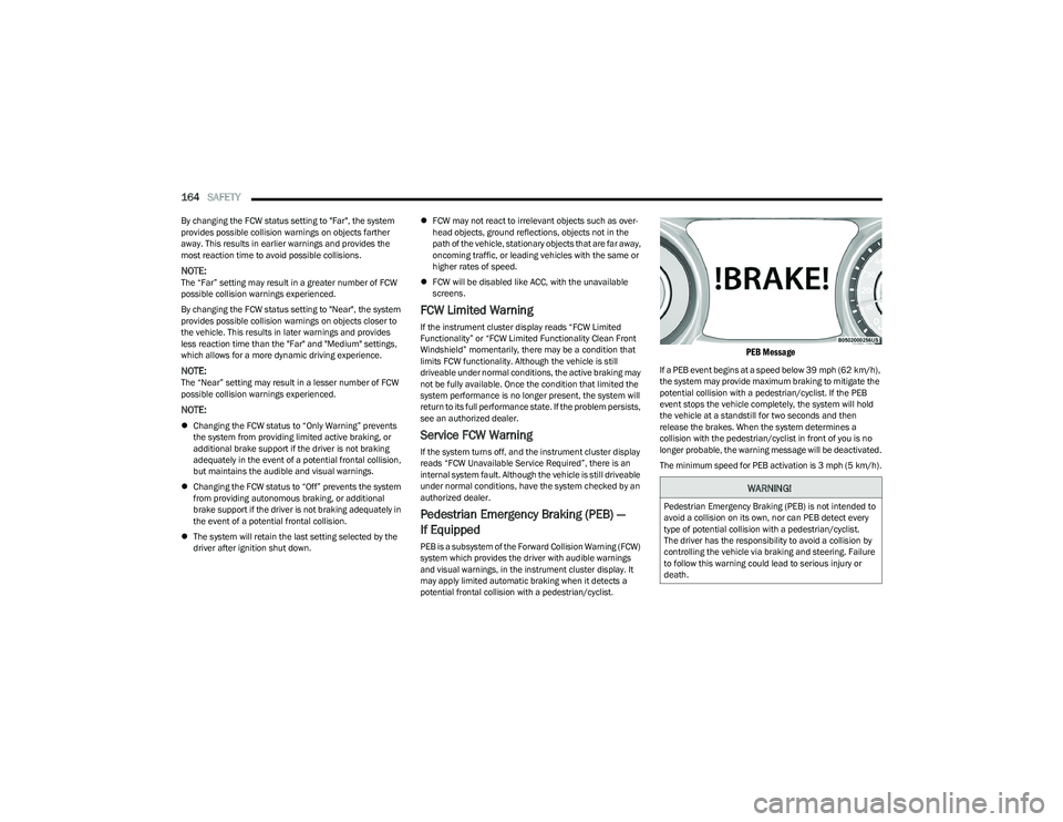
PEB Message
If a PEB event begins at a speed below 39 mph (62 km/h),
the system may provide maximum braking to mitigate the
potential collision with a pedestrian/cyclist. If the PEB
event stops the vehicle completely, the system will hold
the vehicle at a standstill for two seconds and then
release the brakes. When the system determines a
collision with the pedestrian/cyclist in front of you is no
longer probable, the warning message will be deactivated.
The minimum speed for PEB activation is 3 mph (5 km/h).
WARNING!
Pedestrian Emergency Braking (PEB) is not intended to
avoid a collision on its own, nor can PEB detect every
type of potential collision with a pedestrian/cyclist.
The driver has the responsibility to avoid a collision by
controlling the vehicle via braking and steering. Failure
to follow this warning could lead to serious injury or
death.
23_GG_OM_EN_USC_t.book Page 164
Page 168 of 288
166SAFETY
NOTE:
The TPMS is not intended to replace normal tire care
and maintenance, or to provide warning of a tire failure
or condition.
The TPMS should not be used as a tire pressure gauge
while adjusting your tire pressure.
Driving on a significantly underinflated tire causes the
tire to overheat and can lead to tire failure. Underinfla -
tion also reduces fuel efficiency and tire tread life, and
may affect the vehicle’s handling and stopping ability.
The TPMS is not a substitute for proper tire mainte -
nance, and it is the driver’s responsibility to maintain
correct tire pressure using an accurate tire pressure
gauge, even if underinflation has not reached the level
to trigger illumination of the Tire Pressure Monitoring
System Warning Light.
Seasonal temperature changes will affect tire pres -
sure, and the TPMS will monitor the actual tire pres -
sure in the tire.
Premium System
The Tire Pressure Monitoring System (TPMS) uses wireless
technology with wheel rim mounted electronic sensors to
monitor tire pressure levels. Sensors, mounted to each
wheel as part of the valve stem, transmit tire pressure
readings to the receiver module.
NOTE:It is particularly important for you to check the tire
pressure in all of the tires on your vehicle monthly and to
maintain the proper pressure.
The TPMS consists of the following components:
Receiver module
Four Tire Pressure Monitoring System sensors
Various Tire Pressure Monitoring System messages,
which will display in the instrument cluster display
Tire Pressure Monitoring System Warning Light
Tire Pressure Monitoring System Low
Pressure Warnings
The Tire Pressure Monitoring System Warning
Light will illuminate in the instrument cluster
and a chime will sound when tire pressure is
low in one or more of the four active road tires.
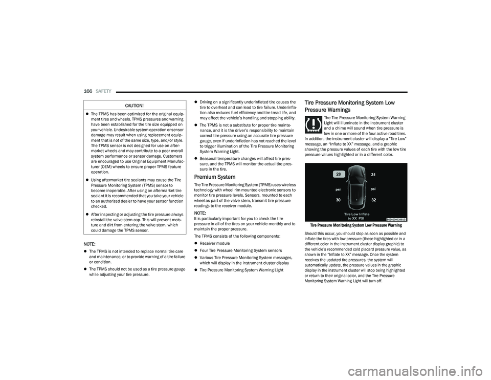
In addition, the instrument cluster will display a "Tire Low"
message, an “Inflate to XX” message, and a graphic
showing the pressure values of each tire with the low tire
pressure values highlighted or in a different color.
Tire Pressure Monitoring System Low Pressure Warning
Should this occur, you should stop as soon as possible and
inflate the tires with low pressure (those highlighted or in a
different color in the instrument cluster display graphic) to
the vehicle’s recommended cold placard pressure value, as
shown in the “Inflate to XX” message. Once the system
receives the updated tire pressures, the system will
automatically update, the pressure values in the graphic
display in the instrument cluster will stop being highlighted
or return to their original color, and the Tire Pressure
Monitoring System Warning Light will turn off.
CAUTION!
The TPMS has been optimized for the original equip -
ment tires and wheels. TPMS pressures and warning
have been established for the tire size equipped on
your vehicle. Undesirable system operation or sensor
damage may result when using replacement equip -
ment that is not of the same size, type, and/or style.
The TPMS sensor is not designed for use on after -
market wheels and may contribute to a poor overall
system performance or sensor damage. Customers
are encouraged to use Original Equipment Manufac -
turer (OEM) wheels to ensure proper TPMS feature
operation.
Using aftermarket tire sealants may cause the Tire
Pressure Monitoring System (TPMS) sensor to
become inoperable. After using an aftermarket tire
sealant it is recommended that you take your vehicle
to an authorized dealer to have your sensor function
checked.
After inspecting or adjusting the tire pressure always
reinstall the valve stem cap. This will prevent mois -
ture and dirt from entering the valve stem, which
could damage the TPMS sensor.
23_GG_OM_EN_USC_t.book Page 166
Page 169 of 288
SAFETY167
NOTE:When filling warm tires, the tire pressure may need to be
increased up to an additional 4 psi (28 kPa) above the
recommended cold placard pressure in order to turn the
Tire Pressure Monitoring System Warning Light off.
The vehicle may need to be driven for up to 20 minutes
above 15 mph (24 km/h) in order for the TPMS to receive
this information.
Service TPMS Warning
When a system fault is detected, the Tire Pressure
Monitoring System Warning Light will flash on and off for
75 seconds and then remain on solid. The system fault will
also sound a chime. In addition, the instrument cluster will
display a "SERVICE TPM SYSTEM" message for a minimum
of five seconds and then display dashes (--) in place of the
pressure value to indicate which sensor is not being
received.
If the ignition key is cycled, this sequence will repeat,
providing the system fault still exists. If the system fault no
longer exists, the Tire Pressure Monitoring System
Warning Light will no longer flash, and the “SERVICE TPM
SYSTEM” message will no longer display, and a pressure
value will display in place of the dashes. A system fault can
occur due to any of the following:
Jamming due to electronic devices or driving next to
facilities emitting the same radio frequencies as the
TPMS sensors
Installing some form of aftermarket window tinting that
affects radio wave signals
Lots of snow or ice around the wheels or wheel hous -
ings
Using tire chains on the vehicle
Using wheels/tires not equipped with TPMS sensors
Vehicles With Compact Spare Or Non-Matching Full Size
Spare
1. The compact spare tire or non-matching full size does not have a Tire Pressure Monitoring System
sensor. Therefore, the TPMS will not monitor the
pressure in the compact or non-matching full size
spare tire.
2. If you install the compact or non-matching full size spare tire in place of a road tire that has a pressure
below the low-pressure warning limit, upon the next
ignition key cycle, the Tire Pressure Monitoring
System Warning Light will remain on and a chime will
sound. In addition, the graphic in the instrument
cluster will still display a different color or highlighted
pressure value and the “Inflate to XX” message.
3. After driving the vehicle for up to 20 minutes above 15 mph (24 km/h), the Tire Pressure Monitoring System Warning Light will flash on and off for
75 seconds and then remain on solid. In addition,
the instrument cluster will display a “SERVICE TPM
SYSTEM” message for five seconds and then display
dashes (--) in place of the pressure value.
4. For each subsequent ignition key cycle, a chime will sound, the Tire Pressure Monitoring System Warning
Light will flash on and off for 75 seconds and then
remain on solid, and the instrument cluster will
display a “SERVICE TPM SYSTEM” message for
five seconds and then display dashes (--) in place of
the pressure value. 5. Once you repair or replace the original road tire and
reinstall it on the vehicle in place of the compact
spare or non-matching full size, the TPMS will update
automatically. In addition, the Tire Pressure
Monitoring System Warning Light will turn off and the
graphic in the instrument cluster will display a new
pressure value instead of dashes (--), as long as no
tire pressure is below the low-pressure warning limit
in any of the four active road tires. The vehicle may
need to be driven for up to 20 minutes above 15 mph
(24 km/h) in order for the TPMS to receive this
information.
TPMS Deactivation — If Equipped
The TPMS can be deactivated if replacing all four wheel
and tire assemblies (road tires) with wheel and tire
assemblies that do not have TPMS sensors, such as when
installing winter wheel and tire assemblies on your
vehicle.
To deactivate the TPMS, first replace all four wheel and
tire assemblies (road tires) with tires not equipped with
Tire Pressure Monitoring System (TPMS) sensors. Then,
drive the vehicle for 20 minutes above 15 mph (24 km/h).
The TPMS will chime, the Tire Pressure Monitoring System
Warning Light will flash on and off for 75 seconds and then
remain on. The instrument cluster will display the
“SERVICE TPM SYSTEM” message and then display
dashes (--) in place of the pressure values.
Beginning with the next ignition cycle, the TPMS will no
longer chime or display the “SERVICE TPM SYSTEM”
message in the instrument cluster but dashes (--) will
remain in place of the pressure values.
6
23_GG_OM_EN_USC_t.book Page 167
Page 170 of 288
168SAFETY
To reactivate the TPMS, replace all four wheel and tire
assemblies (road tires) with tires equipped with TPMS
sensors. Then, drive the vehicle for up to 20 minutes
above 15 mph (24 km/h). The TPMS will chime, the Tire
Pressure Monitoring System Warning Light will flash on
and off for 75 seconds and then turn off. The instrument
cluster will display the “SERVICE TPM SYSTEM” message
and then display pressure values in place of the dashes.
On the next ignition cycle the "SERVICE TPM SYSTEM"
message will no longer be displayed as long as no system
fault exists.
OCCUPANT RESTRAINT SYSTEMS
Some of the most important safety features in your vehicle
are the restraint systems:
OCCUPANT RESTRAINT SYSTEMS
F
EATURES
Seat Belt Systems
Supplemental Restraint Systems (SRS) Air Bags
Child Restraints
Some of the safety features described in this section may
be standard equipment on some models, or may be
optional equipment on others. If you are not sure, ask an
authorized dealer.
IMPORTANT SAFETY PRECAUTIONS
Please pay close attention to the information in this
section. It tells you how to use your restraint system
properly, to keep you and your passengers as safe as
possible.
Here are some simple steps you can take to minimize the
risk of harm from a deploying air bag:
1. Children 12 years old and under should always ride buckled up in the rear seat of a vehicle with a rear
seat.
2. A child who is not big enough to wear the vehicle seat belt properly must be secured in the appropriate child
restraint or belt-positioning booster seat in a rear
seating position
Úpage 188.
3. If a child from 2 to 12 years old (not in a rear-facing child restraint) must ride in the front passenger seat,
move the seat as far back as possible and use the
proper child restraint
Úpage 188.
4. Never allow children to slide the shoulder belt behind them or under their arm.
5. You should read the instructions provided with your child restraint to make sure that you are using it
properly.
6. All occupants should always wear their lap and shoulder belts properly. 7. The driver and front passenger seats should be
moved back as far as practical to allow the front air
bags room to inflate.
8. Do not lean against the door or window. If your vehicle has side air bags, and deployment occurs, the side air
bags will inflate forcefully into the space between
occupants and the door and occupants could be
injured.
9. If the air bag system in this vehicle needs to be modified to accommodate a disabled person, see
Úpage 270 for customer service contact
information.
WARNING!
Never place a rear-facing child restraint in front of an
air bag. A deploying passenger front air bag can
cause death or serious injury to a child 12 years or
younger, including a child in a rear-facing child
restraint.
Never install a rear-facing child restraint in the front
seat of a vehicle. Only use a rear-facing child
restraint in the rear seat. If the vehicle does not have
a rear seat, do not transport a rear-facing child
restraint in that vehicle.
23_GG_OM_EN_USC_t.book Page 168
Page 187 of 288
SAFETY185
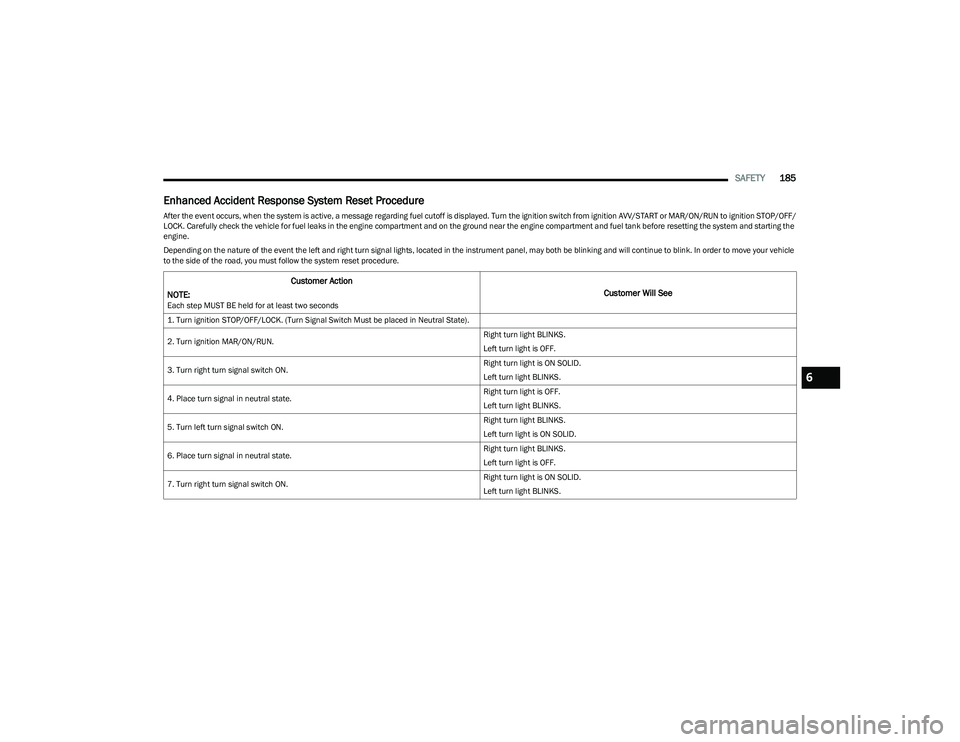
Enhanced Accident Response System Reset Procedure
After the event occurs, when the system is active, a message regarding fuel cutoff is displayed. Turn the ignition switch from ignition AVV/START or MAR/ON/RUN to ignition STOP/OFF/
LOCK. Carefully check the vehicle for fuel leaks in the engine compartment and on the ground near the engine compartment and fuel tank before resetting the system and starting the
engine.
Depending on the nature of the event the left and right turn signal lights, located in the instrument panel, may both be blinking and will continue to blink. In order to move your vehicle
to the side of the road, you must follow the system reset procedure.
Customer Action
NOTE:
Each step MUST BE held for at least two seconds
Customer Will See
1. Turn ignition STOP/OFF/LOCK. (Turn Signal Switch Must be placed in Neutral State).
2. Turn ignition MAR/ON/RUN. Right turn light BLINKS.
Left turn light is OFF.
3. Turn right turn signal switch ON. Right turn light is ON SOLID.
Left turn light BLINKS.
4. Place turn signal in neutral state. Right turn light is OFF.
Left turn light BLINKS.
5. Turn left turn signal switch ON. Right turn light BLINKS.
Left turn light is ON SOLID.
6. Place turn signal in neutral state. Right turn light BLINKS.
Left turn light is OFF.
7. Turn right turn signal switch ON. Right turn light is ON SOLID.
Left turn light BLINKS.
6
23_GG_OM_EN_USC_t.book Page 185
Page 207 of 288
IN CASE OF EMERGENCY205
SOS Call System Limitations
Vehicles sold in Mexico DO NOT have SOS Call system
capabilities.
SOS or other emergency line operators in Mexico may not
answer or respond to SOS system calls.
If the SOS Call system detects a malfunction, any of the
following may occur at the time the malfunction is
detected, and at the beginning of each ignition cycle:
The light located next to the SOS button will continu -
ously illuminate red.
The Device Screen will display the following message
“Vehicle device requires service. Please contact an
authorized dealer.”
An In-Vehicle Audio message will state “Vehicle device
requires service. Please contact an authorized dealer.” Even if the SOS Call system is fully functional, factors
beyond FCA US LLC’s control may prevent or stop the
SOS Call system operation. These include, but are not
limited to, the following factors:
The ignition is in the OFF position
The vehicle’s electrical systems are not intact
The SOS Call system software and/or hardware are
damaged during a crash
The vehicle battery loses power or becomes discon -
nected during a vehicle crash
LTE (voice/data) or 4G (data) network and/or Global
Positioning Satellite signals are unavailable or
obstructed
Equipment malfunction at the SOS operator facility
Operator error by the SOS operator
LTE (voice/data) or 4G (data) network congestion
Weather
Buildings, structures, geographic terrain, or tunnels
NOTE:
Your vehicle may be transmitting data as authorized by
the subscriber Úpage 275.
Never place anything on or near the vehicle’s
LTE (voice/data) or 4G (data) and GPS antennas.
You could prevent LTE (voice/data) or 4G (data) and
GPS signal reception, which can prevent your vehicle
from placing an emergency call. An operable LTE
(voice/data) or 4G (data) network connection and a
GPS signal is required for the SOS Call system to
function properly.
Changes or modifications not expressly approved by
the party responsible for compliance could void the
user's authority to operate the equipment.
WARNING!
Ignoring the overhead console light could mean you
will not have SOS Call services. If the overhead
console light is illuminated, have an authorized
dealer service the SOS Call system immediately.
The Occupant Restraint Control module turns on the
air bag Warning Light on the instrument panel if a
malfunction in any part of the system is detected.
If the Air Bag Warning Light is illuminated, have an
authorized dealer service the Occupant Restraint
Control system immediately.
WARNING!
ALWAYS obey traffic laws and pay attention to the road.
ALWAYS drive safely with your hands on the steering
wheel. You have full responsibility and assume all risks
related to the use of the features and applications in
this vehicle. Only use the features and applications
when it is safe to do so. Failure to do so may result in an
accident involving serious injury or death.
7
23_GG_OM_EN_USC_t.book Page 205
Page 225 of 288
223
SERVICING AND MAINTENANCE
SCHEDULED SERVICING
Your vehicle is equipped with an automatic oil change
indicator system. The oil change indicator system will
remind you that it is time to take your vehicle in for
scheduled maintenance.
Based on engine operation conditions, the oil change
indicator message will illuminate in the instrument cluster.
This means that service is required for your vehicle.
Operating conditions such as frequent short-trips, trailer
towing, and extremely hot or cold ambient temperatures
will influence when the “Change Oil” or “Oil Change
Required” message is displayed. Have your vehicle
serviced as soon as possible, within the next 500 miles
(805 km).An authorized dealer will reset the oil change indicator
message after completing the scheduled oil change. If a
scheduled oil change is performed by someone other than
an authorized dealer, the message can be reset by
referring to the steps described under Instrument Cluster
Display
Úpage 66.
NOTE:Under no circumstances should oil change intervals
exceed 10,000 miles (16,000 km), one year or 350 hours
of engine run time, whichever comes first. The 350 hours
of engine run or idle time is generally only a concern for
fleet customers.
Once A Month Or Before A Long Trip:
Check engine oil level.
Check windshield washer fluid level.
Check the tire inflation pressures and look for unusual
wear or damage. Rotate tires at the first sign of irreg -
ular wear, even if it occurs before the oil indicator
system turns on.
Check the fluid levels of the coolant reservoir, and
brake master cylinder reservoir, and fill as needed.
Check function of all interior and exterior lights.
8
23_GG_OM_EN_USC_t.book Page 223
Page 282 of 288
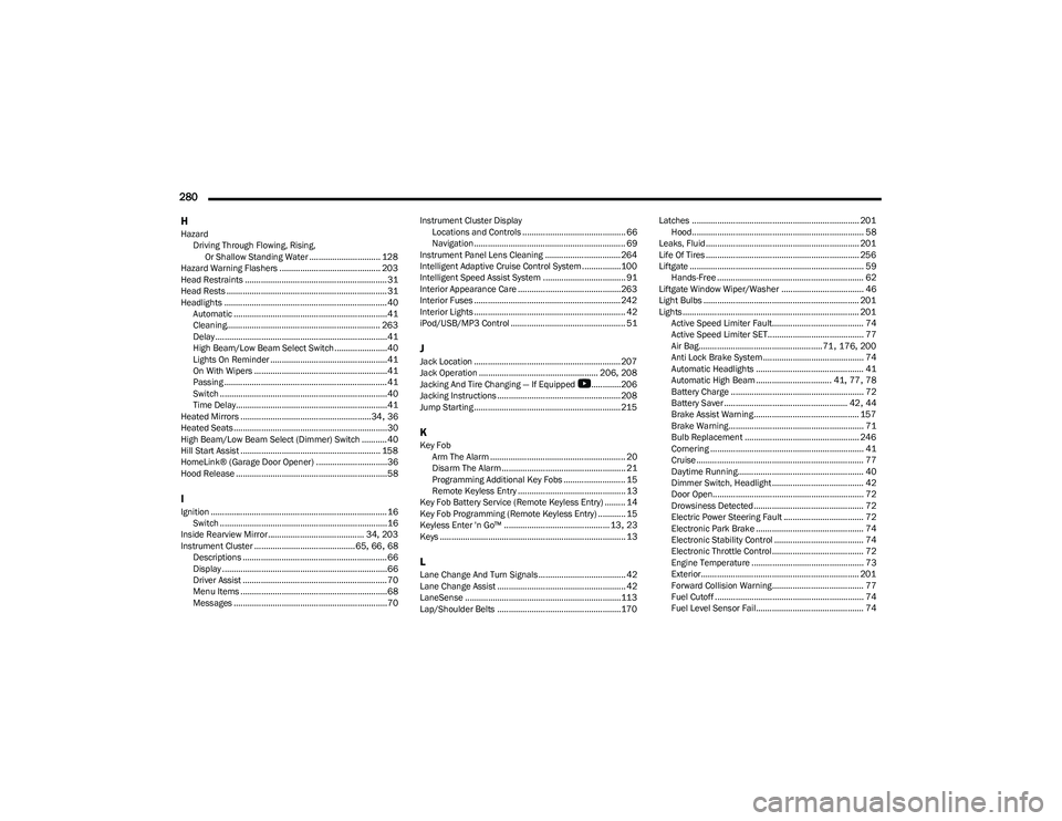
280 H
Hazard Driving Through Flowing, Rising, Or Shallow Standing Water ............................... 128
Hazard Warning Flashers ............................................ 203
Head Restraints .............................................................. 31
Head Rests ...................................................................... 31
Headlights ....................................................................... 40 Automatic ...................................................................41
Cleaning................................................................... 263
Delay ...........................................................................41
High Beam/Low Beam Select Switch .......................40
Lights On Reminder ...................................................41
On With Wipers ..........................................................41
Passing ....................................................................... 41
Switch .........................................................................40
Time Delay..................................................................41
Heated Mirrors .........................................................34
, 36
Heated Seats...................................................................30
High Beam/Low Beam Select (Dimmer) Switch ...........40
Hill Start Assist ............................................................. 158
HomeLink® (Garage Door Opener) ...............................36
Hood Release ..................................................................58
IIgnition .............................................................................16 Switch .........................................................................16
Inside Rearview Mirror.......................................... 34
, 203
Instrument Cluster ............................................ 65, 66, 68
Descriptions ............................................................... 66
Display ........................................................................66
Driver Assist ............................................................... 70
Menu Items ................................................................68
Messages ...................................................................70 Instrument Cluster Display
Locations and Controls ............................................. 66
Navigation .................................................................. 69
Instrument Panel Lens Cleaning ................................. 264
Intelligent Adaptive Cruise Control System.................100
Intelligent Speed Assist System .................................... 91
Interior Appearance Care ............................................. 263
Interior Fuses ................................................................ 242
Interior Lights .................................................................. 42
iPod/USB/MP3 Control .................................................. 51
JJack Location ................................................................ 207
Jack Operation .................................................... 206, 208
Jacking And Tire Changing — If Equipped
b
............. 206
Jacking Instructions ...................................................... 208
Jump Starting ................................................................ 215
KKey Fob Arm The Alarm ........................................................... 20
Disarm The Alarm ...................................................... 21
Programming Additional Key Fobs ........................... 15
Remote Keyless Entry ............................................... 13
Key Fob Battery Service (Remote Keyless Entry) ......... 14
Key Fob Programming (Remote Keyless Entry) ............ 15
Keyless Enter 'n Go™ .............................................. 13
, 23
Keys ................................................................................. 13
LLane Change And Turn Signals...................................... 42 Lane Change Assist ........................................................ 42
LaneSense ....................................................................113
Lap/Shoulder Belts ...................................................... 170 Latches ......................................................................... 201
Hood........................................................................... 58
Leaks, Fluid................................................................... 201
Life Of Tires ................................................................... 256
Liftgate ............................................................................ 59 Hands-Free ................................................................ 62
Liftgate Window Wiper/Washer .................................... 46
Light Bulbs .................................................................... 201
Lights ............................................................................. 201 Active Speed Limiter Fault........................................ 74
Active Speed Limiter SET.......................................... 77
Air Bag...................................................... 71
, 176, 200
Anti Lock Brake System ............................................ 74
Automatic Headlights ............................................... 41
Automatic High Beam ................................. 41
, 77, 78
Battery Charge .......................................................... 72
Battery Saver ...................................................... 42
, 44
Brake Assist Warning.............................................. 157
Brake Warning........................................................... 71
Bulb Replacement .................................................. 246
Cornering ................................................................... 41
Cruise ......................................................................... 77
Daytime Running....................................................... 40
Dimmer Switch, Headlight ........................................ 42
Door Open.................................................................. 72
Drowsiness Detected ................................................ 72
Electric Power Steering Fault ................................... 72
Electronic Park Brake ............................................... 74
Electronic Stability Control ....................................... 74
Electronic Throttle Control ........................................ 72
Engine Temperature ................................................. 73
Exterior..................................................................... 201 Forward Collision Warning........................................ 77
Fuel Cutoff ................................................................. 74
Fuel Level Sensor Fail............................................... 74
23_GG_OM_EN_USC_t.book Page 280