fuel type DODGE HORNET 2023 Owners Manual
[x] Cancel search | Manufacturer: DODGE, Model Year: 2023, Model line: HORNET, Model: DODGE HORNET 2023Pages: 288, PDF Size: 14.2 MB
Page 8 of 288
6
SERVICING AND MAINTENANCE
SCHEDULED SERVICING ................................................ 223
Maintenance Plan ..................................................... 224
ENGINE COMPARTMENT................................................. 226 2.0L Engine .............................................................. 226Checking Oil Level ..................................................... 227
Adding Washer Fluid ................................................ 227Maintenance-Free Battery........................................ 227Pressure Washing ..................................................... 228
VEHICLE MAINTENANCE ................................................. 228 Engine Oil................................................................... 228
Engine Oil Filter ......................................................... 228
Engine Air Cleaner Filter ........................................... 229
Air Conditioner Maintenance ................................... 229
Body Lubrication ....................................................... 230Wiper Blades ............................................................ 230
Exhaust System ........................................................ 232
Cooling System.......................................................... 233
Brake System ........................................................... 236
Automatic Transmission —
If Equipped ................................................................ 236
Fuses ......................................................................... 237
Bulb Replacement ................................................... 246
TIRES ................................................................................ 246 Tire Safety Information ............................................ 246
Tires — General Information .................................... 254
Tire Types................................................................... 257
Spare Tires — If Equipped ........................................ 258Snow Traction Devices ............................................ 259
Tire Rotation Recommendations ............................ 260 DEPARTMENT OF TRANSPORTATION UNIFORM
TIRE QUALITY GRADES .................................................. 260
Treadwear ................................................................. 260Traction Grades ........................................................ 261Temperature Grades ................................................ 261
STORING THE VEHICLE ................................................... 261
BODYWORK ...................................................................... 262 Protection From Atmospheric Agents ...................... 262Body And Underbody Maintenance ......................... 262
Preserving The Bodywork ......................................... 263
INTERIORS ....................................................................... 263 Seats And Fabric Parts ............................................. 263
Plastic And Coated Parts .......................................... 264Leather Surfaces ...................................................... 264
Glass Surfaces ......................................................... 264
TECHNICAL SPECIFICATIONS
VEHICLE IDENTIFICATION NUMBER (VIN)..................... 265
BRAKE SYSTEM .............................................................. 265
WHEEL AND TIRE TORQUE SPECIFICATIONS .............. 265 Torque Specifications ............................................... 265
FUEL REQUIREMENTS ..................................................... 266 2.0L Engine ............................................................... 266Reformulated Gasoline ........................................... 266Gasoline/Oxygenate Blends ................................... 266E-85 Usage In Non-Flex Fuel Vehicles ..................... 267CNG And LP Fuel System Modifications.................. 267
Methylcyclopentadienyl Manganese
Tricarbonyl (MMT) In Gasoline ................................. 267
Materials Added To Fuel .......................................... 267Fuel System Cautions ............................................... 267 FLUID CAPACITIES ...........................................................268
ENGINE FLUIDS AND LUBRICANTS ................................269
CHASSIS FLUIDS AND LUBRICANTS ..............................269
CUSTOMER ASSISTANCE
SUGGESTIONS FOR OBTAINING SERVICE FOR
YOUR VEHICLE ................................................................. 270 Prepare For The Appointment .................................. 270
Prepare A List ............................................................ 270Be Reasonable With Requests ................................. 270
IF YOU NEED ASSISTANCE .............................................270 Roadside Assistance ................................................. 271
FCA US LLC Customer Center ................................... 272
FCA Canada Inc. Customer Care .............................. 272
Mexico ........................................................................ 272
Puerto Rico And US Virgin Islands............................ 272
Customer Assistance For The Hearing Or
Speech Impaired (TDD/TTY) ..................................... 272
Service Contract ....................................................... 272
WARRANTY INFORMATION.............................................273
MOPAR® PARTS ..............................................................273
REPORTING SAFETY DEFECTS ......................................273 In The 50 United States And Washington, D.C........ 273
In Canada................................................................... 273
PUBLICATION ORDER FORMS .......................................274
CHANGE OF OWNERSHIP OR ADDRESS.......................274
GENERAL INFORMATION................................................. 275
23_GG_OM_EN_USC_t.book Page 6
Page 69 of 288
GETTING TO KNOW YOUR INSTRUMENT PANEL67
The systems allow the driver to select information by
pushing the following buttons mounted on the steering
wheel:
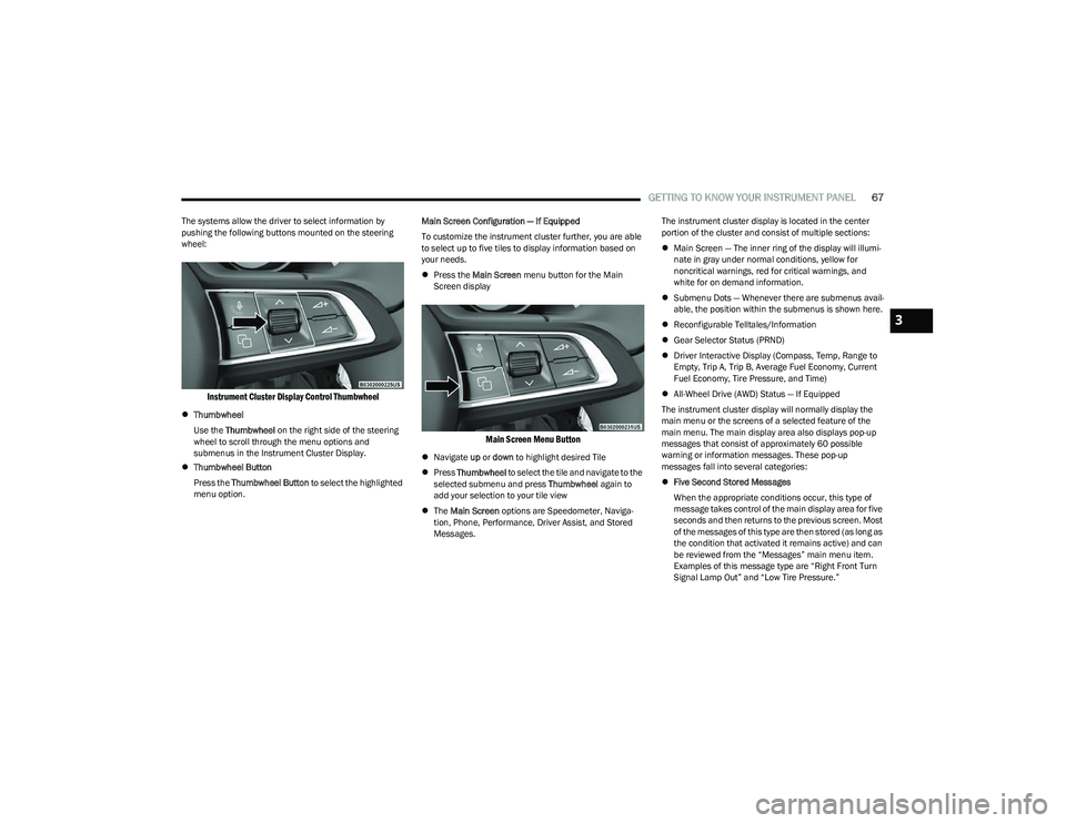
Instrument Cluster Display Control Thumbwheel
Thumbwheel
Use the Thumbwheel on the right side of the steering
wheel to scroll through the menu options and
submenus in the Instrument Cluster Display.
Thumbwheel Button
Press the Thumbwheel Button to select the highlighted
menu option. Main Screen Configuration — If Equipped
To customize the instrument cluster further, you are able
to select up to five tiles to display information based on
your needs.
Press the Main Screen menu button for the Main
Screen display
Main Screen Menu Button
Navigate up or down to highlight desired Tile
Press Thumbwheel to select the tile and navigate to the
selected submenu and press Thumbwheel again to
add your selection to your tile view
The Main Screen options are Speedometer, Naviga -
tion, Phone, Performance, Driver Assist, and Stored
Messages. The instrument cluster display is located in the center
portion of the cluster and consist of multiple sections:
Main Screen — The inner ring of the display will illumi -
nate in gray under normal conditions, yellow for
noncritical warnings, red for critical warnings, and
white for on demand information.
Submenu Dots — Whenever there are submenus avail -
able, the position within the submenus is shown here.
Reconfigurable Telltales/Information
Gear Selector Status (PRND)
Driver Interactive Display (Compass, Temp, Range to
Empty, Trip A, Trip B, Average Fuel Economy, Current
Fuel Economy, Tire Pressure, and Time)
All-Wheel Drive (AWD) Status — If Equipped
The instrument cluster display will normally display the
main menu or the screens of a selected feature of the
main menu. The main display area also displays pop-up
messages that consist of approximately 60 possible
warning or information messages. These pop-up
messages fall into several categories:
Five Second Stored Messages
When the appropriate conditions occur, this type of
message takes control of the main display area for five
seconds and then returns to the previous screen. Most
of the messages of this type are then stored (as long as
the condition that activated it remains active) and can
be reviewed from the “Messages” main menu item.
Examples of this message type are “Right Front Turn
Signal Lamp Out” and “Low Tire Pressure.”
3
23_GG_OM_EN_USC_t.book Page 67
Page 70 of 288
68GETTING TO KNOW YOUR INSTRUMENT PANEL
Unstored Messages
This message type is displayed indefinitely or until the
condition that activated the message is cleared. Exam -
ples of this message type are “Turn Signal On” (if a turn
signal is left on) and “Lights On” (if driver leaves the
vehicle with the lights on).
Unstored Messages Until RUN
These messages deal primarily with the Remote Start
feature. This message type is displayed until the igni -
tion is in the RUN state. Examples of this message type
are “Remote Start Canceled - Door Ajar” and
“Press Brake Pedal and Push Button to Start.”
Five Second Unstored Messages
When the appropriate conditions occur, this type of
message takes control of the main display area for
five seconds and then returns to the previous screen.
An example of this message type is “Automatic High
Beams On.”
OIL CHANGE RESET
Use this QR code to access your digital
experience.
Your vehicle is equipped with an
engine oil change indicator system.
A message will display in the instru -
ment cluster display for five
seconds to indicate the next sched -
uled oil change interval is due. The
engine oil change indicator system is duty cycle based,
which means the engine oil change interval may fluc -
tuate, dependent upon your personal driving style.
Unless reset, this message will continue to display
each time the ignition is cycled to the ON/RUN position.
To reset the oil change indicator after performing the
scheduled maintenance, refer to the following procedure:
1. Without pressing the brake pedal, push the ENGINE START/STOP button and cycle the ignition to the
ON/RUN position (do not start the engine).
2. Fully press the accelerator pedal, slowly, three times within ten seconds.
3. Cycle the ignition to the OFF position.
NOTE:If the indicator message illuminates when you start the
vehicle, the oil change indicator system did not reset. If
necessary, repeat this procedure.
OIL CHANGE INDICATOR SYSTEM
Your vehicle is equipped with an engine oil change
indicator system. The “Oil Change Due” message will
display in the instrument cluster display for five seconds
after a single chime has sounded, to indicate the next
scheduled oil change interval. The engine oil change
indicator system is duty cycle based, which means the
engine oil change interval may fluctuate, dependent upon
your personal driving style.
GEAR SHIFT INDICATOR (GSI) —
I
F EQUIPPED
The GSI system is enabled on vehicles with a manual
transmission, or when a vehicle with an automatic
transmission is in manual shift mode. The GSI provides
the driver with a visual indication when the recommended gear shift point has been reached. This indication notifies
the driver that changing gear will allow a reduction in fuel
consumption. When the up shift indicator is shown on the
instrument cluster display, the GSI is advising the driver to
engage a higher gear. When the down shift indicator is
shown on the display, the GSI is advising the driver to
engage a lower gear.
The GSI remains illuminated until the driver changes
gears, or the driving conditions return to a situation where
changing gear is not required to improve fuel
consumption.
INSTRUMENT CLUSTER DISPLAY MENU
I
TEMS
The instrument cluster display can be used to view the
main menu items for several features. Use the up and
down arrow buttons to scroll through the driver
interactive display menu options until the desired menu is
reached.
NOTE:The instrument cluster display menu items display in the
center of the instrument cluster. Menu items may vary
depending on your vehicle features.
Main Menu
Use the Thumbwheel to scroll Up and Down through the
Menu options. Press the Thumbwheel to enter and exit the
highlighted menu option.
NOTE:These Menu options may vary based on your vehicles trim
level.
23_GG_OM_EN_USC_t.book Page 68
Page 78 of 288
76GETTING TO KNOW YOUR INSTRUMENT PANEL
Each tire, including the spare (if provided), should be
checked monthly when cold and inflated to the inflation
pressure recommended by the vehicle manufacturer on
the vehicle placard or tire inflation pressure label. If your
vehicle has tires of a different size than the size indicated
on the vehicle placard or tire inflation pressure label, you
should determine the proper tire inflation pressure for
those tires.
As an added safety feature, your vehicle has been equipped
with a TPMS that illuminates a low tire pressure telltale
when one or more of your tires is significantly underinflated.
Accordingly, when the low tire pressure telltale illuminates,
you should stop and check your tires as soon as possible,
and inflate them to the proper pressure. Driving on a
significantly underinflated tire causes the tire to overheat
and can lead to tire failure. Underinflation also reduces fuel
efficiency and tire tread life, and may affect the vehicle’s
handling and stopping ability.
Please note that the TPMS is not a substitute for proper
tire maintenance, and it is the driver’s responsibility to
maintain correct tire pressure, even if underinflation has
not reached the level to trigger illumination of the TPMS
low tire pressure telltale. Your vehicle has also been equipped with a TPMS
malfunction indicator to indicate when the system is not
operating properly. The TPMS malfunction indicator is
combined with the low tire pressure telltale. When the
system detects a malfunction, the telltale will flash for
approximately one minute and then remain continuously
illuminated. This sequence will continue upon subsequent
vehicle start-ups as long as the malfunction exists. When
the malfunction indicator is illuminated, the system may
not be able to detect or signal low tire pressure as
intended. TPMS malfunctions may occur for a variety of
reasons, including the installation of replacement or
alternate tires or wheels on the vehicle that prevent the
TPMS from functioning properly. Always check the TPMS
malfunction telltale after replacing one or more tires or
wheels on your vehicle to ensure that the replacement or
alternate tires and wheels allow the TPMS to continue to
function properly.
Towing Hook Breakdown Warning Light —
If Equipped
This light illuminates when there is a failure
with the tow hook. Contact an authorized
dealer for service.
Traffic Sign Recognition (TSR) Fault
Warning Light
This light will illuminate to indicate a TSR fault.
Contact an authorized dealer if the light
remains on after restarting the engine.
Transmission Temperature Warning Light
This warning light will illuminate to warn of a
high transmission fluid temperature. This may
occur with strenuous usage such as trailer
towing. If this light turns on, stop the vehicle
and run the engine at idle or slightly faster, with the
transmission in PARK or NEUTRAL, until the light turns off.
Once the light turns off, you may continue to drive
normally.
CAUTION!
Do not continue driving with one or more flat tires as
handling may be compromised. Stop the vehicle,
avoiding sharp braking and steering. If a tire puncture
occurs, repair immediately using the dedicated tire
repair kit and contact an authorized dealer as soon
as possible.
CAUTION!
The TPMS has been optimized for the original
equipment tires and wheels. TPMS pressures and
warning have been established for the tire size
equipped on your vehicle. Undesirable system
operation or sensor damage may result when using
replacement equipment that is not of the same size,
type, and/or style. Aftermarket wheels can cause
sensor damage. Using aftermarket tire sealants may
cause the Tire Pressure Monitoring System (TPMS)
sensor to become inoperable. After using an
aftermarket tire sealant it is recommended that you
take your vehicle to an authorized dealer to have your
sensor function checked.
WARNING!
If you continue operating the vehicle when the
Transmission Temperature Warning Light is illuminated
you could cause the fluid to boil over, come in contact
with hot engine or exhaust components and cause a
fire.
23_GG_OM_EN_USC_t.book Page 76
Page 83 of 288
STARTING AND OPERATING81
Keyless Enter ’n Go™ — With Driver’s Foot Off The Brake
Pedal (In PARK Or NEUTRAL Position)
The Keyless Enter ’n Go™ feature operates similar to an
ignition switch. It has three positions, OFF, ON/RUN, and
START. To change the ignition switch positions without
starting the vehicle and use the accessories follow, these
steps starting with the ignition switch in the OFF position:
1. Push the ENGINE START/STOP button once to
change the ignition switch to the ON/RUN position.
2. Push the ENGINE START/STOP button a second time to change the ignition switch to the OFF position.
COLD WEATHER OPERATION
(B
ELOW –22°F OR −30°C)
To ensure reliable starting at these temperatures, use of
an externally powered electric engine block heater
(available from an authorized dealer) is recommended.
EXTENDED PARK STARTING
NOTE:Extended Park condition occurs when the vehicle has not
been started or driven for at least 30 days.
1. Install a battery charger or jumper cables to the
battery to ensure a full battery charge during the
crank cycle.
2. Place the ignition in the START position and release it when the engine starts. For Keyless Enter ‘n Go™
ignition systems, press and hold the brake pedal
while pushing the ENGINE START/STOP button once. 3. If the engine fails to start within 10 seconds, place
the ignition in the OFF position, wait 10 to 15 seconds
to allow the starter to cool, then repeat the “Extended
Park Starting” procedure.
4. If the engine fails to start after eight attempts, allow the starter to cool for at least 10 minutes, then repeat
the procedure.
AFTER STARTING — WARMING UP THE
E
NGINE
The idle speed is controlled automatically and it will
decrease as the engine warms up.
IF ENGINE FAILS TO START
If the engine fails to start after you have followed the
“Normal Starting” procedure, and has not experienced an
Extended Park condition as identified in “Extended Park
Starting” procedure, it may be flooded. Push the
accelerator pedal all the way to the floor and hold it there.
Crank the engine for no more than 10 seconds. This
should clear any excess fuel in case the engine is flooded.
Leave the ignition key in the ON/RUN position, release the
accelerator pedal and repeat the “Normal Starting”
procedure.
CAUTION!
To prevent damage to the starter, do not crank
continuously for more than 10 seconds at a time. Wait
10 to 15 seconds before trying again.
CAUTION!
To prevent damage to the starter, do not continuously
crank the engine for more than 10 seconds at a time.
Wait 10 to 15 seconds before trying again.
WARNING!
Never pour fuel or other flammable liquid into the
throttle body air inlet opening in an attempt to start
the vehicle. This could result in flash fire causing
serious personal injury.
Do not attempt to push or tow your vehicle to get it
started. Vehicles equipped with an automatic trans -
mission cannot be started this way. Unburned fuel
could enter the catalytic converter and once the
engine has started, ignite and damage the converter
and vehicle.
If the vehicle has a discharged battery, booster
cables may be used to obtain a start from a booster
battery or the battery in another vehicle. This type of
start can be dangerous if done improperly
Úpage 215.
4
23_GG_OM_EN_USC_t.book Page 81
Page 90 of 288
88STARTING AND OPERATING
In the event of a momentary problem, the transmission
can be reset to regain all forward gears by performing the
following steps:
1. Stop the vehicle.
2. Shift the transmission into PARK (P), if possible. If
not, shift the transmission to NEUTRAL.
3. Push and hold the ignition until the engine turns off.
4. Wait approximately 30 seconds.
5. Restart the engine.
6. Shift into the desired gear range. If the problem is no longer detected, the transmission will return to
normal operation.
NOTE:Even if the transmission can be reset, we recommend that
you visit an authorized dealer at your earliest possible
convenience. An authorized dealer has diagnostic
equipment to assess the condition of your transmission.
If the transmission cannot be reset, authorized dealer
service is required.
TORQUE CONVERTER CLUTCH
A feature designed to improve fuel economy has been
included in the automatic transmission on your vehicle.
A clutch within the torque converter engages
automatically at calibrated speeds. This may result in a
slightly different feeling or response during normal
operation in the upper gears. When the vehicle speed
drops or during some accelerations, the clutch
automatically disengages.
NOTE:The torque converter clutch will not engage until the
engine and/or transmission is warm (usually after 1 to
3 miles [2 to 5 km] of driving). Because the engine speed
is higher when the torque converter clutch is not engaged,
it may seem as if the transmission is not shifting properly
when the vehicle is cold. This is normal. The torque
converter clutch will function normally once the powertrain
is sufficiently warm.
ALL-WHEEL DRIVE (AWD)
This feature provides on-demand All-Wheel Drive (AWD).
The system is automatic with no driver inputs or additional
driving skills required. Under normal driving conditions,
the front wheels provide most of the traction. If the front
wheels begin to lose traction, power is shifted
automatically to the rear wheels. The greater the front
wheel traction loss, the greater the power transfer to the
rear wheels.
Additionally, on dry pavement under heavy throttle input
(where one may have no wheel spin), torque will be sent to
the rear in a preemptive effort to improve vehicle launch
and performance characteristics.
SPORT MODE — IF EQUIPPED
Your vehicle is equipped with a SPORT Mode feature. The
engine, transmission, and steering systems are all set to
their SPORT settings. SPORT Mode will provide improved
throttle response and modified transmission shift points
for an enhanced driving experience, as well as greater
amount of steering feel.
This mode may be activated and deactivated by pushing
the SPORT button on the steering wheel. For PHEV
versions the SPORT button is located below the STOP/
START button.
POWER STEERING
The electric power steering system will provide increased
vehicle response and ease of maneuverability. The electric
power steering system adapts to different driving conditions.
If the “SERVICE POWER STEERING” or “POWER
STEERING ASSIST OFF - SERVICE SYSTEM”
message and a steering wheel icon display on
the instrument cluster, it indicates that the
vehicle needs service. It may be necessary to perform the
recalibration maneuver by turning the steering wheel from
full left position to full right position. If the problem is still
present, take the vehicle to an authorized dealer for
service. It is likely the vehicle has lost power steering
assistance
Úpage 66.
CAUTION!
All wheels must have the same size and type tires.
Unequal tire sizes must not be used. Unequal tire size
may cause failure of the power transfer unit.
WARNING!
Continued operation with reduced assist could pose a
safety risk to yourself and others. Service should be
obtained as soon as possible.
23_GG_OM_EN_USC_t.book Page 88
Page 123 of 288
STARTING AND OPERATING121
Inflation Pressure
This is the cold tire inflation pressure for your vehicle for
all loading conditions up to full GAWR.
Curb Weight
The curb weight of a vehicle is defined as the total weight
of the vehicle with all fluids, including vehicle fuel, at full
capacity conditions, and with no occupants or cargo
loaded into the vehicle. The front and rear curb weight
values are determined by weighing your vehicle on a
commercial scale before any occupants or cargo are
added.
Loading
The actual total weight and the weight of the front and rear
of your vehicle at the ground can best be determined by
weighing it when it is loaded and ready for operation.
The entire vehicle should first be weighed on a commercial
scale to ensure that the GVWR has not been exceeded.
The weight on the front and rear of the vehicle should then
be determined separately to be sure that the load is
properly distributed over the front and rear axle. Weighing
the vehicle may show that the GAWR of either the front or
rear axles has been exceeded but the total load is within
the specified GVWR. If so, weight must be shifted from
front to rear or rear to front as appropriate until the
specified weight limitations are met. Store the heavier
items down low and be sure that the weight is distributed
equally. Stow all loose items securely before driving.
Improper weight distributions can have an adverse effect
on the way your vehicle steers and handles and the way
the brakes operate.
TRAILER TOWING
In this section you will find safety tips and information on
limits to the type of towing you can reasonably do with your
vehicle. Before towing a trailer, carefully review this
information to tow your load as efficiently and safely as
possible.
To maintain the New Vehicle Limited Warranty coverage,
follow the requirements and recommendations in this
manual concerning vehicles used for trailer towing.
COMMON TOWING DEFINITIONS
The following trailer towing related definitions will assist
you in understanding the following information:
Gross Vehicle Weight Rating (GVWR)
The GVWR is the total allowable weight of your vehicle.
This includes driver, passengers, cargo and tongue
weight. The total load must be limited so that you do not
exceed the GVWR
Úpage 120.
Gross Trailer Weight (GTW)
The GTW is the weight of the trailer plus the weight of all
cargo, consumables and equipment (permanent or
temporary) loaded in or on the trailer in its "loaded and
ready for operation" condition.
The recommended way to measure GTW is to put your fully
loaded trailer on a vehicle scale. The entire weight of the
trailer must be supported by the scale.
Gross Axle Weight Rating (GAWR)
The GAWR is the maximum capacity of the front and rear
axles. Distribute the load over the front and rear axles
evenly. Make sure that you do not exceed either front or
rear GAWR
Úpage 120.
Tongue Weight (TW)
The TW is the downward force exerted on the hitch ball by
the trailer. You must consider this as part of the load on
your vehicle.
Trailer Frontal Area
The frontal area is the maximum height multiplied by the
maximum width of the front of a trailer.
WARNING!
Do not load your vehicle any heavier than the GVWR or
the maximum front and rear GAWR. If you do, parts on
your vehicle can break, or it can change the way your
vehicle handles. This could cause you to lose control.
Overloading can shorten the life of your vehicle.
WARNING!
It is important that you do not exceed the maximum
front or rear GAWR. A dangerous driving condition can
result if either rating is exceeded. You could lose control
of the vehicle and have a collision.
4
23_GG_OM_EN_USC_t.book Page 121
Page 168 of 288
166SAFETY
NOTE:
The TPMS is not intended to replace normal tire care
and maintenance, or to provide warning of a tire failure
or condition.
The TPMS should not be used as a tire pressure gauge
while adjusting your tire pressure.
Driving on a significantly underinflated tire causes the
tire to overheat and can lead to tire failure. Underinfla -
tion also reduces fuel efficiency and tire tread life, and
may affect the vehicle’s handling and stopping ability.
The TPMS is not a substitute for proper tire mainte -
nance, and it is the driver’s responsibility to maintain
correct tire pressure using an accurate tire pressure
gauge, even if underinflation has not reached the level
to trigger illumination of the Tire Pressure Monitoring
System Warning Light.
Seasonal temperature changes will affect tire pres -
sure, and the TPMS will monitor the actual tire pres -
sure in the tire.
Premium System
The Tire Pressure Monitoring System (TPMS) uses wireless
technology with wheel rim mounted electronic sensors to
monitor tire pressure levels. Sensors, mounted to each
wheel as part of the valve stem, transmit tire pressure
readings to the receiver module.
NOTE:It is particularly important for you to check the tire
pressure in all of the tires on your vehicle monthly and to
maintain the proper pressure.
The TPMS consists of the following components:
Receiver module
Four Tire Pressure Monitoring System sensors
Various Tire Pressure Monitoring System messages,
which will display in the instrument cluster display
Tire Pressure Monitoring System Warning Light
Tire Pressure Monitoring System Low
Pressure Warnings
The Tire Pressure Monitoring System Warning
Light will illuminate in the instrument cluster
and a chime will sound when tire pressure is
low in one or more of the four active road tires.
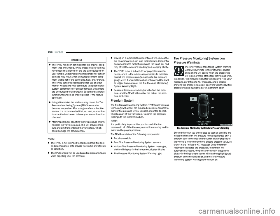
In addition, the instrument cluster will display a "Tire Low"
message, an “Inflate to XX” message, and a graphic
showing the pressure values of each tire with the low tire
pressure values highlighted or in a different color.
Tire Pressure Monitoring System Low Pressure Warning
Should this occur, you should stop as soon as possible and
inflate the tires with low pressure (those highlighted or in a
different color in the instrument cluster display graphic) to
the vehicle’s recommended cold placard pressure value, as
shown in the “Inflate to XX” message. Once the system
receives the updated tire pressures, the system will
automatically update, the pressure values in the graphic
display in the instrument cluster will stop being highlighted
or return to their original color, and the Tire Pressure
Monitoring System Warning Light will turn off.
CAUTION!
The TPMS has been optimized for the original equip -
ment tires and wheels. TPMS pressures and warning
have been established for the tire size equipped on
your vehicle. Undesirable system operation or sensor
damage may result when using replacement equip -
ment that is not of the same size, type, and/or style.
The TPMS sensor is not designed for use on after -
market wheels and may contribute to a poor overall
system performance or sensor damage. Customers
are encouraged to use Original Equipment Manufac -
turer (OEM) wheels to ensure proper TPMS feature
operation.
Using aftermarket tire sealants may cause the Tire
Pressure Monitoring System (TPMS) sensor to
become inoperable. After using an aftermarket tire
sealant it is recommended that you take your vehicle
to an authorized dealer to have your sensor function
checked.
After inspecting or adjusting the tire pressure always
reinstall the valve stem cap. This will prevent mois -
ture and dirt from entering the valve stem, which
could damage the TPMS sensor.
23_GG_OM_EN_USC_t.book Page 166
Page 229 of 288
SERVICING AND MAINTENANCE227
CHECKING OIL LEVEL
To ensure proper engine lubrication, the engine oil must
be maintained at the correct level. Check the oil level at
regular intervals, such as every fuel stop. The best time to
check the engine oil level is about five minutes after a fully
warmed up engine is shut off.
Checking the oil while the vehicle is on level ground will
improve the accuracy of the oil level readings.
There are four possible dipstick types:
Crosshatched zone.
Crosshatched zone marked SAFE.
Crosshatched zone marked with MIN at the low end of
the range and MAX at the high end of the range.
Crosshatched zone marked with dimples at the MIN
and the MAX ends of the range.
NOTE:Always maintain the oil level within the crosshatch
markings on the dipstick.
Adding 1 qt (1 L) of oil when the reading is at the low end
of the dipstick range will raise the oil level to the high end
of the range marking.
ADDING WASHER FLUID
The fluid reservoir is located in the front of the engine
compartment. Be sure to check the fluid level in the
reservoir at regular intervals. Fill the reservoir with
windshield washer solvent (not radiator antifreeze) and
operate the system for a few seconds to flush out the
residual washer fluid.
When refilling the washer fluid reservoir, take some
washer fluid, apply it to a cloth or towel, and wipe clean the
wiper blades; this will help blade performance.
To prevent freeze-up of your windshield washer system in
cold weather, select a solution or mixture that meets or
exceeds the temperature range of your climate. This rating
information can be found on most washer fluid containers.
MAINTENANCE-FREE BATTERY
Your vehicle is equipped with a maintenance-free battery.
You will never have to add water, and periodic
maintenance is not required.CAUTION!
Overfilling or underfilling the engine oil will cause
aeration or loss of oil pressure. This could damage your
engine.
WARNING!
Commercially available windshield washer solvents are
flammable. They could ignite and burn you. Care must
be exercised when filling or working around the washer
solution.
WARNING!
Battery fluid is a corrosive acid solution and can burn
or even blind you. Do not allow battery fluid to
contact your eyes, skin, or clothing. Do not lean over
a battery when attaching clamps. If acid splashes in
eyes or on skin, flush the area immediately with large
amounts of water
Úpage 215.
Battery gas is flammable and explosive. Keep flame
or sparks away from the battery. Do not use a
booster battery or any other booster source with an
output greater than 12 Volts. Do not allow cable
clamps to touch each other.
Battery posts, terminals, and related accessories
contain lead and lead compounds. Wash hands after
handling.
CAUTION!
It is essential when replacing the cables on the
battery that the positive cable is attached to the posi -
tive post and the negative cable is attached to the
negative post. Battery posts are marked positive (+)
and negative (-) and are identified on the battery
case. Cable clamps should be tight on the terminal
posts and free of corrosion.
If a “fast charger” is used while the battery is in the
vehicle, disconnect both vehicle battery cables
before connecting the charger to the battery. Do not
use a “fast charger” to provide starting voltage.
8
23_GG_OM_EN_USC_t.book Page 227
Page 256 of 288
254SERVICING AND MAINTENANCE
(Continued)
TIRES — GENERAL INFORMATION
Tire Pressure
Proper tire inflation pressure is essential to the safe and
satisfactory operation of your vehicle. Four primary areas
are affected by improper tire pressure:
Safety
Fuel Economy
Tread Wear
Ride Comfort and Vehicle Stability
Safety Both underinflation and overinflation affect the stability of
the vehicle and can produce a feeling of sluggish response
or over responsiveness in the steering.
NOTE:
Unequal tire pressures from side to side may cause
erratic and unpredictable steering response.
Unequal tire pressure from side to side may cause the
vehicle to drift left or right.
Fuel Economy
Underinflated tires will increase tire rolling resistance
resulting in higher fuel consumption.
Tread Wear
Improper cold tire inflation pressures can cause abnormal
wear patterns and reduced tread life, resulting in the need
for earlier tire replacement.
Ride Comfort And Vehicle Stability
Proper tire inflation contributes to a comfortable ride.
Overinflation produces a jarring and uncomfortable ride.
Tire Inflation Pressures
The proper cold tire inflation pressure is listed on the
driver's side B-pillar or rear edge of the driver's side door.
At least once a month:
Check and adjust tire pressure with a good quality
pocket-type pressure gauge. Do not make a visual judg -
ment when determining proper inflation. Tires may look
properly inflated even when they are underinflated.
Inspect tires for signs of tire wear or visible damage.
Inflation pressures specified on the placard are always
“cold tire inflation pressure”. Cold tire inflation pressure is
defined as the tire pressure after the vehicle has not been
driven for at least three hours, or driven less than 1 mile
(1.6 km) after sitting for a minimum of three hours. The
cold tire inflation pressure must not exceed the maximum
inflation pressure molded into the tire sidewall.
Check tire pressures more often if subject to a wide range
of outdoor temperatures, as tire pressures vary with
temperature changes.
Tire pressures change by approximately 1 psi (7 kPa) per
12°F (7°C) of air temperature change. Keep this in mind
when checking tire pressure inside a garage, especially in
the Winter.
WARNING!
Improperly inflated tires are dangerous and can
cause collisions.
Underinflation increases tire flexing and can result in
overheating and tire failure.
Overinflation reduces a tire's ability to cushion shock.
Objects on the road and chuckholes can cause
damage that result in tire failure.
Overinflated or underinflated tires can affect vehicle
handling and can fail suddenly, resulting in loss of
vehicle control.
Unequal tire pressures can cause steering problems.
You could lose control of your vehicle.
Unequal tire pressures from one side of the vehicle
to the other can cause the vehicle to drift to the
right or left.
Always drive with each tire inflated to the recom -
mended cold tire inflation pressure.
WARNING!
CAUTION!
After inspecting or adjusting the tire pressure, always
reinstall the valve stem cap. This will prevent moisture
and dirt from entering the valve stem, which could
damage the valve stem.
23_GG_OM_EN_USC_t.book Page 254