trailer DODGE HORNET 2023 Owners Manual
[x] Cancel search | Manufacturer: DODGE, Model Year: 2023, Model line: HORNET, Model: DODGE HORNET 2023Pages: 288, PDF Size: 14.2 MB
Page 7 of 288
5
TRAILER TOWING............................................................. 121Common Towing Definitions .................................... 121
Trailer Towing Weights
(Maximum Trailer Weight Ratings) .......................... 122Trailer And Tongue Weight ....................................... 123
Towing Requirements .............................................. 123
Towing Tips ............................................................... 125
RECREATIONAL TOWING (BEHIND MOTORHOME) .... 126 Towing This Vehicle Behind Another Vehicle .......... 126
Recreational Towing ................................................. 127
DRIVING TIPS ................................................................... 127 Driving On Slippery Surfaces.................................... 127
Driving Through Water ............................................. 128
MULTIMEDIA
UCONNECT SYSTEMS ..................................................... 129
CYBERSECURITY ............................................................. 129
UCONNECT SETTINGS ..................................................... 130Customer Programmable Features ......................... 130
STEERING WHEEL AUDIO CONTROLS —
IF EQUIPPED .................................................................... 150 Steering Wheel Rotary Control ................................. 150Controls on Central Tunnel....................................... 151
MY CAR ............................................................................. 151
PERFORMANCE PAGES .................................................. 152 Technical Gauges...................................................... 152Consumption History ................................................ 152Accessory Gauges ..................................................... 153
RADIO OPERATION AND MOBILE PHONES .................. 153 Regulatory And Safety Information .......................... 153
SAFETY
SAFETY FEATURES .......................................................... 154Anti-Lock Brake System (ABS) ................................ 154
Electronic Brake Control (EBC) System .................. 155
AUXILIARY DRIVING SYSTEMS ...................................... 159 Blind Spot Monitoring (BSM) —
If Equipped ................................................................ 159Forward Collision Warning (FCW)
With Mitigation — If Equipped .................................. 162
Tire Pressure Monitoring System (TPMS) ............... 165
OCCUPANT RESTRAINT SYSTEMS ............................... 168 Occupant Restraint Systems Features ................... 168
Important Safety Precautions .................................. 168
Seat Belt Systems .................................................... 169
Supplemental Restraint Systems (SRS).................. 175
Child Restraints ........................................................ 188
SAFETY TIPS .................................................................... 199 Transporting Passengers ......................................... 199
Transporting Pets .................................................... 199
Connected Vehicles .................................................. 199Safety Checks You Should Make Inside
The Vehicle ............................................................... 200Periodic Safety Checks You Should Make Outside
The Vehicle ................................................................ 201Exhaust Gas .............................................................. 202
Carbon Monoxide Warnings ..................................... 202
IN CASE OF EMERGENCY
HAZARD WARNING FLASHERS ......................................203
SOS SYSTEM — IF EQUIPPED.......................................... 203
JACKING AND TIRE CHANGING —
IF EQUIPPED
b
...............................................................206
Preparations For Jacking ......................................... 206
Jack And Tools Location/Spare Tire Stowage —
If Equipped................................................................. 207
Jacking Instructions ................................................. 208
TIRE INFLATOR KIT — IF EQUIPPED
b
........................211
Description................................................................. 211
Inflation Procedure.................................................... 212
Checking And Restoring Tire Pressure..................... 214
Sealant Cartridge Replacement ............................... 214
JUMP STARTING ...............................................................215 Preparations For Jump Start..................................... 215
Jump Starting Procedure .......................................... 216
REFUELING IN EMERGENCY ........................................... 217
IF YOUR ENGINE OVERHEATS ........................................218
GEAR SELECTOR OVERRIDE .......................................... 218
FREEING A STUCK VEHICLE ........................................... 219
TOWING A DISABLED VEHICLE.......................................220 Without The Key Fob ................................................. 221
All-Wheel Drive (AWD) Models ................................. 221
Tow Eye — If Equipped .............................................. 221
ENHANCED ACCIDENT RESPONSE
SYSTEM (EARS) ...............................................................222
EVENT DATA RECORDER (EDR)......................................222
23_GG_OM_EN_USC_t.book Page 5
Page 78 of 288
76GETTING TO KNOW YOUR INSTRUMENT PANEL
Each tire, including the spare (if provided), should be
checked monthly when cold and inflated to the inflation
pressure recommended by the vehicle manufacturer on
the vehicle placard or tire inflation pressure label. If your
vehicle has tires of a different size than the size indicated
on the vehicle placard or tire inflation pressure label, you
should determine the proper tire inflation pressure for
those tires.
As an added safety feature, your vehicle has been equipped
with a TPMS that illuminates a low tire pressure telltale
when one or more of your tires is significantly underinflated.
Accordingly, when the low tire pressure telltale illuminates,
you should stop and check your tires as soon as possible,
and inflate them to the proper pressure. Driving on a
significantly underinflated tire causes the tire to overheat
and can lead to tire failure. Underinflation also reduces fuel
efficiency and tire tread life, and may affect the vehicle’s
handling and stopping ability.
Please note that the TPMS is not a substitute for proper
tire maintenance, and it is the driver’s responsibility to
maintain correct tire pressure, even if underinflation has
not reached the level to trigger illumination of the TPMS
low tire pressure telltale. Your vehicle has also been equipped with a TPMS
malfunction indicator to indicate when the system is not
operating properly. The TPMS malfunction indicator is
combined with the low tire pressure telltale. When the
system detects a malfunction, the telltale will flash for
approximately one minute and then remain continuously
illuminated. This sequence will continue upon subsequent
vehicle start-ups as long as the malfunction exists. When
the malfunction indicator is illuminated, the system may
not be able to detect or signal low tire pressure as
intended. TPMS malfunctions may occur for a variety of
reasons, including the installation of replacement or
alternate tires or wheels on the vehicle that prevent the
TPMS from functioning properly. Always check the TPMS
malfunction telltale after replacing one or more tires or
wheels on your vehicle to ensure that the replacement or
alternate tires and wheels allow the TPMS to continue to
function properly.
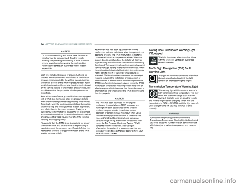
Towing Hook Breakdown Warning Light —
If Equipped
This light illuminates when there is a failure
with the tow hook. Contact an authorized
dealer for service.
Traffic Sign Recognition (TSR) Fault
Warning Light
This light will illuminate to indicate a TSR fault.
Contact an authorized dealer if the light
remains on after restarting the engine.
Transmission Temperature Warning Light
This warning light will illuminate to warn of a
high transmission fluid temperature. This may
occur with strenuous usage such as trailer
towing. If this light turns on, stop the vehicle
and run the engine at idle or slightly faster, with the
transmission in PARK or NEUTRAL, until the light turns off.
Once the light turns off, you may continue to drive
normally.
CAUTION!
Do not continue driving with one or more flat tires as
handling may be compromised. Stop the vehicle,
avoiding sharp braking and steering. If a tire puncture
occurs, repair immediately using the dedicated tire
repair kit and contact an authorized dealer as soon
as possible.
CAUTION!
The TPMS has been optimized for the original
equipment tires and wheels. TPMS pressures and
warning have been established for the tire size
equipped on your vehicle. Undesirable system
operation or sensor damage may result when using
replacement equipment that is not of the same size,
type, and/or style. Aftermarket wheels can cause
sensor damage. Using aftermarket tire sealants may
cause the Tire Pressure Monitoring System (TPMS)
sensor to become inoperable. After using an
aftermarket tire sealant it is recommended that you
take your vehicle to an authorized dealer to have your
sensor function checked.
WARNING!
If you continue operating the vehicle when the
Transmission Temperature Warning Light is illuminated
you could cause the fluid to boil over, come in contact
with hot engine or exhaust components and cause a
fire.
23_GG_OM_EN_USC_t.book Page 76
Page 79 of 288
GETTING TO KNOW YOUR INSTRUMENT PANEL77
YELLOW INDICATOR LIGHTS
Exterior Lights Failure Indicator Light
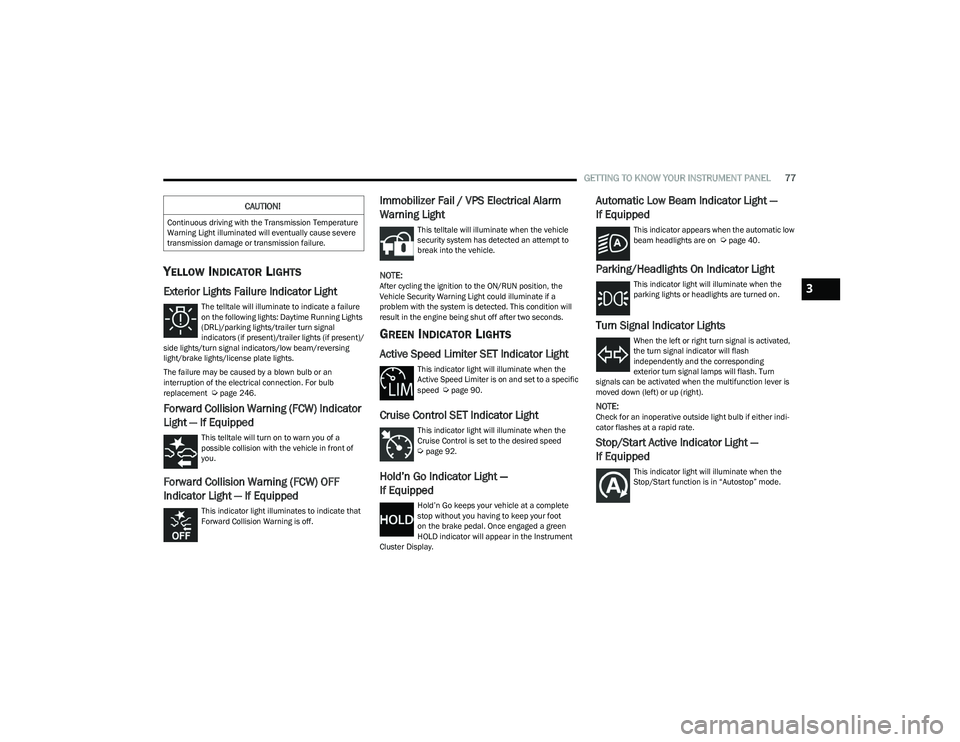
The telltale will illuminate to indicate a failure
on the following lights: Daytime Running Lights
(DRL)/parking lights/trailer turn signal
indicators (if present)/trailer lights (if present)/
side lights/turn signal indicators/low beam/reversing
light/brake lights/license plate lights.
The failure may be caused by a blown bulb or an
interruption of the electrical connection. For bulb
replacement
Úpage 246.
Forward Collision Warning (FCW) Indicator
Light — If Equipped
This telltale will turn on to warn you of a
possible collision with the vehicle in front of
you.
Forward Collision Warning (FCW) OFF
Indicator Light — If Equipped
This indicator light illuminates to indicate that
Forward Collision Warning is off.
Immobilizer Fail / VPS Electrical Alarm
Warning Light
This telltale will illuminate when the vehicle
security system has detected an attempt to
break into the vehicle.
NOTE:After cycling the ignition to the ON/RUN position, the
Vehicle Security Warning Light could illuminate if a
problem with the system is detected. This condition will
result in the engine being shut off after two seconds.
GREEN INDICATOR LIGHTS
Active Speed Limiter SET Indicator Light
This indicator light will illuminate when the
Active Speed Limiter is on and set to a specific
speed
Úpage 90.
Cruise Control SET Indicator Light
This indicator light will illuminate when the
Cruise Control is set to the desired speed
Úpage 92.
Hold’n Go Indicator Light —
If Equipped
Hold’n Go keeps your vehicle at a complete
stop without you having to keep your foot
on the brake pedal. Once engaged a green
HOLD indicator will appear in the Instrument
Cluster Display.
Automatic Low Beam Indicator Light —
If Equipped
This indicator appears when the automatic low
beam headlights are on Úpage 40.
Parking/Headlights On Indicator Light
This indicator light will illuminate when the
parking lights or headlights are turned on.
Turn Signal Indicator Lights
When the left or right turn signal is activated,
the turn signal indicator will flash
independently and the corresponding
exterior turn signal lamps will flash. Turn
signals can be activated when the multifunction lever is
moved down (left) or up (right).
NOTE:Check for an inoperative outside light bulb if either indi -
cator flashes at a rapid rate.
Stop/Start Active Indicator Light —
If Equipped
This indicator light will illuminate when the
Stop/Start function is in “Autostop” mode.
CAUTION!
Continuous driving with the Transmission Temperature
Warning Light illuminated will eventually cause severe
transmission damage or transmission failure.
3
23_GG_OM_EN_USC_t.book Page 77
Page 95 of 288
STARTING AND OPERATING93
(Continued)
ACC will allow you to keep Cruise Control engaged in light
to moderate traffic conditions without the constant need
to reset your speed. ACC utilizes a radar sensor and a
forward facing camera designed to detect a vehicle
directly ahead of you to maintain a set speed.
NOTE:
If the ACC sensor detects a vehicle ahead, ACC will
apply limited braking or accelerate (not to exceed the
original set speed) automatically to maintain a preset
following distance, while matching the speed of the
vehicle ahead.
Any chassis/suspension or tire size modifications to
the vehicle will affect the performance of the Adaptive
Cruise Control and Forward Collision Warning system.
Adaptive Cruise Control (ACC) Operation
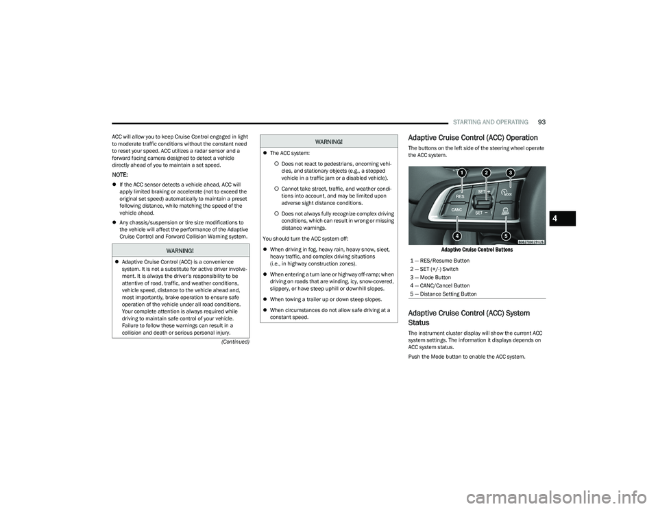
The buttons on the left side of the steering wheel operate
the ACC system.
Adaptive Cruise Control Buttons
Adaptive Cruise Control (ACC) System
Status
The instrument cluster display will show the current ACC
system settings. The information it displays depends on
ACC system status.
Push the Mode button to enable the ACC system.
WARNING!
Adaptive Cruise Control (ACC) is a convenience
system. It is not a substitute for active driver involve -
ment. It is always the driver’s responsibility to be
attentive of road, traffic, and weather conditions,
vehicle speed, distance to the vehicle ahead and,
most importantly, brake operation to ensure safe
operation of the vehicle under all road conditions.
Your complete attention is always required while
driving to maintain safe control of your vehicle.
Failure to follow these warnings can result in a
collision and death or serious personal injury.
The ACC system:
Does not react to pedestrians, oncoming vehi -
cles, and stationary objects (e.g., a stopped
vehicle in a traffic jam or a disabled vehicle).
Cannot take street, traffic, and weather condi -
tions into account, and may be limited upon
adverse sight distance conditions.
Does not always fully recognize complex driving
conditions, which can result in wrong or missing
distance warnings.
You should turn the ACC system off:
When driving in fog, heavy rain, heavy snow, sleet,
heavy traffic, and complex driving situations
(i.e., in highway construction zones).
When entering a turn lane or highway off-ramp; when
driving on roads that are winding, icy, snow-covered,
slippery, or have steep uphill or downhill slopes.
When towing a trailer up or down steep slopes.
When circumstances do not allow safe driving at a
constant speed.
WARNING!
1 — RES/Resume Button
2 — SET (+/-) Switch
3 — Mode Button
4 — CANC/Cancel Button
5 — Distance Setting Button
4
23_GG_OM_EN_USC_t.book Page 93
Page 97 of 288
STARTING AND OPERATING95
To Cancel
The following conditions cancel ACC:
The brake pedal is applied
The CANC (cancel) button is pushed
The Anti-Lock Brake System (ABS) activates
The gear selector is removed from the DRIVE position
The Electronic Stability Control/Traction Control
System (ESC/TCS) activates
The vehicle parking brake is applied
The Trailer Sway Control (TSC) activates
The driver switches ESC to Full Off mode
The braking temperature exceeds normal range
(overheated)
Driver seat belt is unbuckled at low speeds
Driver door is opened at low speeds
To Turn Off
The system will turn off and clear the set speed in memory
if:
The Mode button is pushed
The ignition is placed in the OFF position
To Resume
If ACC was canceled, and there is a set speed in memory,
push the RES (resume) button and remove your foot from
the accelerator pedal. The instrument cluster display will
show the last set speed. Resume can be used at any speed above 0 mph (0 km/h)
when ACC is active.
NOTE:ACC cannot be resumed if there is a stationary vehicle in
front of your vehicle in close proximity.
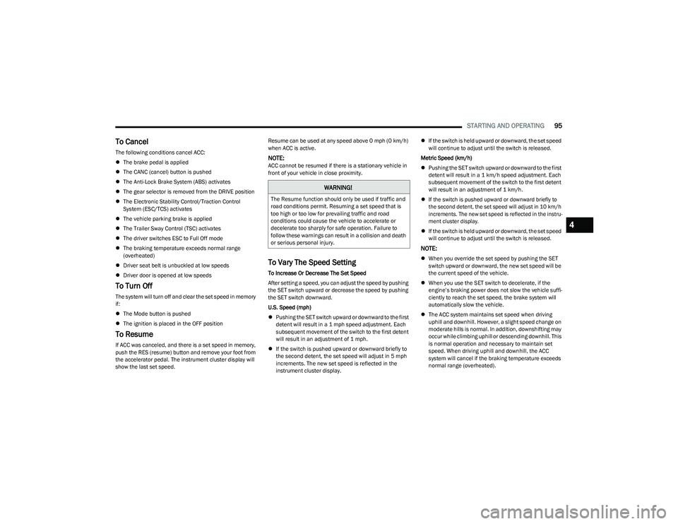
To Vary The Speed Setting
To Increase Or Decrease The Set Speed
After setting a speed, you can adjust the speed by pushing
the SET switch upward or decrease the speed by pushing
the SET switch downward.
U.S. Speed (mph)
Pushing the SET switch upward or downward to the first
detent will result in a 1 mph speed adjustment. Each
subsequent movement of the switch to the first detent
will result in an adjustment of 1 mph.
If the switch is pushed upward or downward briefly to
the second detent, the set speed will adjust in 5 mph
increments. The new set speed is reflected in the
instrument cluster display.
If the switch is held upward or downward, the set speed
will continue to adjust until the switch is released.
Metric Speed (km/h)
Pushing the SET switch upward or downward to the first
detent will result in a 1 km/h speed adjustment. Each
subsequent movement of the switch to the first detent
will result in an adjustment of 1 km/h.
If the switch is pushed upward or downward briefly to
the second detent, the set speed will adjust in 10 km/h
increments. The new set speed is reflected in the instru -
ment cluster display.
If the switch is held upward or downward, the set speed
will continue to adjust until the switch is released.
NOTE:
When you override the set speed by pushing the SET
switch upward or downward, the new set speed will be
the current speed of the vehicle.
When you use the SET switch to decelerate, if the
engine’s braking power does not slow the vehicle suffi -
ciently to reach the set speed, the brake system will
automatically slow the vehicle.
The ACC system maintains set speed when driving
uphill and downhill. However, a slight speed change on
moderate hills is normal. In addition, downshifting may
occur while climbing uphill or descending downhill. This
is normal operation and necessary to maintain set
speed. When driving uphill and downhill, the ACC
system will cancel if the braking temperature exceeds
normal range (overheated).
WARNING!
The Resume function should only be used if traffic and
road conditions permit. Resuming a set speed that is
too high or too low for prevailing traffic and road
conditions could cause the vehicle to accelerate or
decelerate too sharply for safe operation. Failure to
follow these warnings can result in a collision and death
or serious personal injury.
4
23_GG_OM_EN_USC_t.book Page 95
Page 99 of 288
STARTING AND OPERATING97
Display Warnings And Maintenance
LIMITED OPERATION WARNING
If a warning message appears in the instrument cluster
display indicating limited operation of the ACC system, a
fault or obstruction of the system’s radar or camera may
have occurred.
If an obstruction is detected, clean the area of the
windshield opposite the interior rearview mirror, where the
camera is located, as well as the area of the front fascia/
bumper where the sensor is located. Then check that the
message has disappeared.
When the conditions limiting the system function as been
corrected, normal operation will resume.
Should the fault persist, contact an authorized dealer.
Precautions While Driving With ACC
In certain driving situations, ACC may have detection
issues. In these cases, ACC may brake late or
unexpectedly. The driver needs to stay alert and may need
to intervene. The following are examples of these types of
situations:
TOWING A TRAILER
Towing a trailer is not recommended when using ACC.
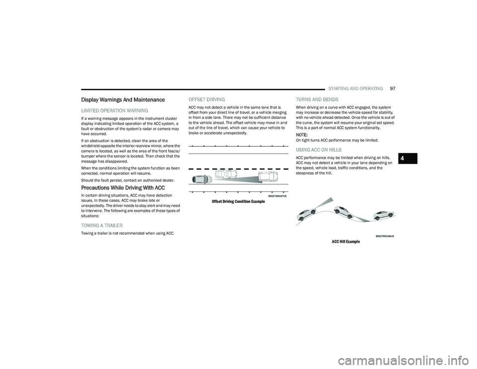
OFFSET DRIVING
ACC may not detect a vehicle in the same lane that is
offset from your direct line of travel, or a vehicle merging
in from a side lane. There may not be sufficient distance
to the vehicle ahead. The offset vehicle may move in and
out of the line of travel, which can cause your vehicle to
brake or accelerate unexpectedly.
Offset Driving Condition Example
TURNS AND BENDS
When driving on a curve with ACC engaged, the system
may increase or decrease the vehicle speed for stability,
with no vehicle ahead detected. Once the vehicle is out of
the curve, the system will resume your original set speed.
This is a part of normal ACC system functionality.
NOTE:On tight turns ACC performance may be limited.
USING ACC ON HILLS
ACC performance may be limited when driving on hills.
ACC may not detect a vehicle in your lane depending on
the speed, vehicle load, traffic conditions, and the
steepness of the hill.
ACC Hill Example
4
23_GG_OM_EN_USC_t.book Page 97
Page 102 of 288
100STARTING AND OPERATING
(Continued)
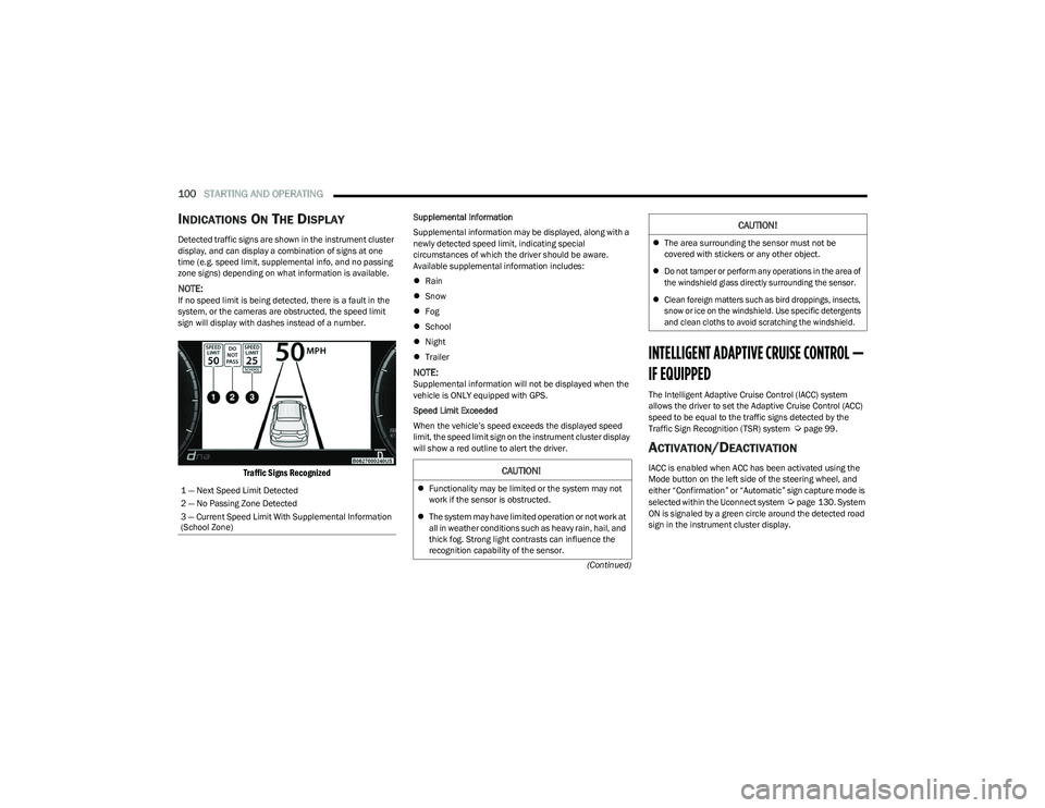
INDICATIONS ON THE DISPLAY
Detected traffic signs are shown in the instrument cluster
display, and can display a combination of signs at one
time (e.g. speed limit, supplemental info, and no passing
zone signs) depending on what information is available.
NOTE:If no speed limit is being detected, there is a fault in the
system, or the cameras are obstructed, the speed limit
sign will display with dashes instead of a number.
Traffic Signs Recognized
Supplemental Information
Supplemental information may be displayed, along with a
newly detected speed limit, indicating special
circumstances of which the driver should be aware.
Available supplemental information includes:
Rain
Snow
Fog
School
Night
Trailer
NOTE:Supplemental information will not be displayed when the
vehicle is ONLY equipped with GPS.
Speed Limit Exceeded
When the vehicle’s speed exceeds the displayed speed
limit, the speed limit sign on the instrument cluster display
will show a red outline to alert the driver.
INTELLIGENT ADAPTIVE CRUISE CONTROL —
IF EQUIPPED
The Intelligent Adaptive Cruise Control (IACC) system
allows the driver to set the Adaptive Cruise Control (ACC)
speed to be equal to the traffic signs detected by the
Traffic Sign Recognition (TSR) system
Úpage 99.
ACTIVATION/DEACTIVATION
IACC is enabled when ACC has been activated using the
Mode button on the left side of the steering wheel, and
either “Confirmation” or “Automatic” sign capture mode is
selected within the Uconnect system
Úpage 130. System
ON is signaled by a green circle around the detected road
sign in the instrument cluster display.
1 — Next Speed Limit Detected
2 — No Passing Zone Detected
3 — Current Speed Limit With Supplemental Information
(School Zone)
CAUTION!
Functionality may be limited or the system may not
work if the sensor is obstructed.
The system may have limited operation or not work at
all in weather conditions such as heavy rain, hail, and
thick fog. Strong light contrasts can influence the
recognition capability of the sensor.
The area surrounding the sensor must not be
covered with stickers or any other object.
Do not tamper or perform any operations in the area of
the windshield glass directly surrounding the sensor.
Clean foreign matters such as bird droppings, insects,
snow or ice on the windshield. Use specific detergents
and clean cloths to avoid scratching the windshield.
CAUTION!
23_GG_OM_EN_USC_t.book Page 100
Page 108 of 288
106STARTING AND OPERATING
(Continued)
ENABLING AND DISABLING PARKSENSE
ParkSense can be enabled and disabled with
the ParkSense switch, located in front of the
center console, to the rear of the gear selector.
When the ParkSense switch is pushed to disable the
system, the LED in the switch will illuminate, and the
display will read “Parksense Off” when the vehicle is
shifted into DRIVE or REVERSE.
NOTE:The ParkSense switch LED will be off when the system is
active.
The ParkSense switch LED will also be illuminated when
ParkSense requires service. If the ParkSense switch is
pushed, and requires service, the ParkSense switch LED
will blink momentarily, and then the LED will be on.
SERVICE THE PARKSENSE PARK ASSIST
S
YSTEM
During vehicle start up, when the ParkSense System has
detected a faulted condition, the instrument cluster will
display a warning message associated with the detected
fault.
If "Sensor Lock" appears in the instrument cluster display,
make sure the outer surface and the underside of the rear
fascia/bumper and/or front fascia/bumper is clean and
clear of snow, ice, mud, dirt or other obstructions and then
cycle the ignition. If the message continues to appear, see
an authorized dealer.
If the "System Not Available" message appears in the
instrument cluster display, see an authorized dealer.
CLEANING THE PARKSENSE SYSTEM
Clean the ParkSense sensors with water, car wash soap
and a soft cloth. Do not use rough or hard cloths. Do not
scratch or poke the sensors. Otherwise, you could damage
the sensors.
PARKSENSE SYSTEM USAGE
P
RECAUTIONS
Ensure that the front and rear fascias/bumpers are
free of snow, ice, mud, dirt and debris to keep the Park -
Sense system operating properly.
Jackhammers, large trucks, and other vibrations could
affect the performance of ParkSense.
When you turn ParkSense off, the display will read
“Parksense Off” when the vehicle is shifted into DRIVE
or REVERSE. Furthermore, once you turn ParkSense
off, it remains off until you turn it on again, even if you
cycle the ignition.
ParkSense, when on, will reduce the volume of the
radio when it is sounding a tone.
Clean the ParkSense sensors regularly, taking care not
to scratch or damage them. The sensors must not be
covered with ice, snow, slush, mud, dirt or debris.
Failure to do so can result in the system not working
properly. The ParkSense system might not detect an
obstacle behind or in front of the fascia/bumper, or it
could provide a false indication that an obstacle is
behind or in front of the fascia/bumper.
Use the ParkSense switch to turn the ParkSense
system off if objects such as bicycle carriers, etc. are
attached to the rear fascia/bumper. Failure to do so
can result in the system misinterpreting a close object
as a sensor problem, causing the “System Not Avail -
able” message to be displayed in the instrument
cluster display.
NOTE:If any objects are attached to the fascia/bumper within a
6.5 ft (2 m) field of view, they will interfere and cause false
alerts and possibly blockage.
There may be a delay in the object detection rate if the
object is moving.
The rear sensors are automatically deactivated when
the trailer’s electric plug is inserted in the vehicle’s tow
socket. The front sensors (if equipped) will stay active
and can provide acoustic and visual warnings. The rear
sensors are automatically reactivated when the
trailer's cable plug is removed.
WARNING!
Drivers must be careful when backing up even when
using ParkSense. Always check carefully behind your
vehicle, look behind you, and be sure to check for
pedestrians, animals, other vehicles, obstructions,
and blind spots before backing up. You are respon -
sible for safety and must continue to pay attention to
your surroundings. Failure to do so can result in
serious injury or death.
23_GG_OM_EN_USC_t.book Page 106
Page 110 of 288
108STARTING AND OPERATING
(Continued)
Side Distance Warning Usage Precautions
Some conditions may influence the performance of the
Side Distance Warning system:
NOTE:
Ensure that the front and rear fascias/bumpers are
free of snow, ice, mud, dirt and debris to keep the
ParkSense system operating properly.
Construction equipment, large trucks, and other vibra -
tions could affect the performance of ParkSense.
ParkSense, when on, will reduce the volume of the
radio when it is sounding a tone.
Clean the ParkSense sensors regularly, taking care not
to scratch or damage them. The sensors must not be
covered with ice, snow, slush, mud, dirt or debris.
Failure to do so can result in the system not working
properly. The ParkSense system might not detect an
obstacle behind or in front of the fascia/bumper, or it
could provide a false indication that an obstacle is
behind or in front of the fascia/bumper.
The presence of a tow hook without a trailer may inter -
fere with the correct operation of the parking sensors.
Before using the ParkSense system, it is recom -
mended to remove the removable tow hook ball
assembly and any attachments from the vehicle when
it is not used for towing operations. If you leave the tow
hook fitted when not towing a trailer, the tow hook
could be detected as an obstacle by the sensors.
Contact your authorized dealer to update the
ParkSense system operations.
PARKSENSE ACTIVE PARK ASSIST SYSTEM —
IF EQUIPPED
The ParkSense Active Park Assist system is intended to
assist the driver during parallel, perpendicular, and
parallel park exit maneuvers by identifying a proper
parking space, providing audible/visual instructions, and
controlling the steering wheel. The ParkSense Active Park
Assist system is defined as “semi-automatic” since the
driver maintains control of the accelerator, gear selector
and brakes. Depending on the driver's parking maneuver
selection, the ParkSense Active Park Assist system is
capable of maneuvering a vehicle into a parallel or a
perpendicular parking space on either side (i.e., driver
side or passenger side), as well as exiting a parallel
parking space.
NOTE:
The driver is always responsible for controlling the
vehicle, responsible for any surrounding objects, and
must intervene as required.
The system is designed to assist the driver and not to
substitute the driver.
WARNING!
Drivers must be careful when backing up even when
using ParkSense. Always check carefully behind your
vehicle, look behind you, and be sure to check for
pedestrians, animals, other vehicles, obstructions,
and blind spots before backing up. You are respon -
sible for safety and must continue to pay attention to
your surroundings. Failure to do so can result in
serious injury or death.
Before using ParkSense, it is strongly recommended
that the ball mount and hitch ball assembly be
disconnected from the vehicle when the vehicle is
not used for towing. Failure to do so can result in
injury or damage to vehicles or obstacles because
the hitch ball will be much closer to the obstacle than
the rear fascia/bumper when the vehicle sounds the
continuous tone. Also, the sensors could detect the
ball mount and hitch ball assembly, depending on its
size and shape, giving a false indication that an
obstacle is behind the vehicle.
CAUTION!
ParkSense is only a parking aid and it is unable to
recognize every obstacle, including small obstacles.
Parking curbs might be temporarily detected or not
detected at all. Obstacles located above or below the
sensors will not be detected when they are in close
proximity.
The vehicle must be driven slowly when using
ParkSense in order to be able to stop in time when
an obstacle is detected. It is recommended that
the driver looks over his/her shoulder when using
ParkSense.
CAUTION!
23_GG_OM_EN_USC_t.book Page 108
Page 115 of 288
STARTING AND OPERATING113
Construction equipment, large trucks, and other vibra -
tions could affect the performance of ParkSense.
Sensors may detect a nonexistent obstacle (echo
noise) due to mechanical noises, for example while
washing the vehicle or in the case of rain, strong wind,
and hail.
The sensors may not detect objects of a particular
shape or made from particular materials (very thin
poles, trailer beams, panels, nets, bushes, anti-parking
posts, pavements, rubbish bins, motor vehicles, etc.).
Always take great care to check that the vehicle and its
path are actually compatible with the parking place
identified by the system.
The use of wheels and tires that are different size to the
original equipment could affect the operation of the
system.
The operation of the rear sensors is automatically
deactivated when the trailer's electric plug is inserted
in the vehicle's tow hook socket, while the front
sensors stay active and can provide acoustic and
visual warnings. If this situation occurs, Active Park
Assist will not work. The rear sensors are automatically
reactivated when the trailer's cable plug is removed.
In the case of parking maneuvers on roads with
inclines, the performance of the system could be
inferior and it may deactivate.
If a parking maneuver is being carried out between
two parked vehicles alongside a curb, the system may
cause the vehicle to drive up onto the curb.
Some maneuvers at very tight bends might be impos -
sible to be carried out.
Take great care to ensure that conditions do not
change during the parking maneuver (e.g. if there are
persons and/or animals in the parking place, moving
vehicles, etc.) and intervene immediately if necessary.
During parking maneuvers, pay attention to vehicles
approaching from the opposite direction. Always abide
by the law and road regulations.
NOTE:
Correct system operation is not guaranteed if snow
chains or the compact spare tire are fitted.
The function only informs the driver about the last
appropriate parking place (parallel or perpendicular)
detected by the parking sensors.
Some messages displayed are accompanied by
audible warnings.
LANESENSE — IF EQUIPPED
LANESENSE OPERATION
The LaneSense system is operational at speeds above
37 mph (60 km/h) and below 112 mph (180 km/h). The
LaneSense system uses a forward facing camera to detect
lane markings and measure vehicle position within the
lane boundaries. When both lane markings are detected and the driver
unintentionally drifts out of the lane (no turn signal
applied), the LaneSense system provides a haptic warning
in the form of torque applied to the steering wheel to
prompt the driver to remain within the lane boundaries. If
the driver continues to unintentionally drift out of the lane,
the LaneSense system provides a visual warning through
the instrument cluster display to prompt the driver to
remain within the lane boundaries.
The driver may manually override the haptic warning by
applying torque to the steering wheel at any time.
When only a single lane marking is detected and the driver
unintentionally drifts across the lane marking (no turn
signal applied), the LaneSense system provides a visual
warning through the instrument cluster display to prompt
the driver to remain within the lane. When only a single
lane marking is detected, a haptic (torque) warning will not
be provided.
NOTE:When operating conditions have been met, the Lane
-
Sense system will monitor if the driver’s hands are on the
steering wheel and provides an audible warning to the
driver when the driver’s hands are not detected on the
steering wheel. The system will cancel if the driver does
not return their hands to the wheel.
4
23_GG_OM_EN_USC_t.book Page 113