brake DODGE JOURNEY 2014 1.G Owner's Manual
[x] Cancel search | Manufacturer: DODGE, Model Year: 2014, Model line: JOURNEY, Model: DODGE JOURNEY 2014 1.GPages: 124, PDF Size: 3.37 MB
Page 80 of 124
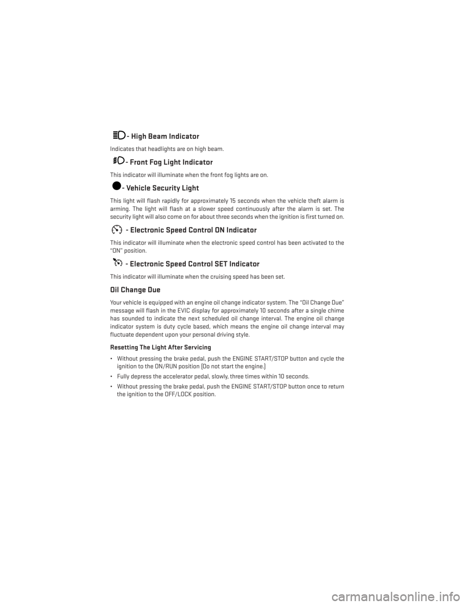
- High Beam Indicator
Indicates that headlights are on high beam.
- Front Fog Light Indicator
This indicator will illuminate when the front fog lights are on.
- Vehicle Security Light
This light will flash rapidly for approximately 15 seconds when the vehicle theft alarm is
arming. The light will flash at a slower speed continuously after the alarm is set. The
security light will also come on for about three seconds when the ignition is first turned on.
- Electronic Speed Control ON Indicator
This indicator will illuminate when the electronic speed control has been activated to the
“ON” position.
- Electronic Speed Control SET Indicator
This indicator will illuminate when the cruising speed has been set.
Oil Change Due
Your vehicle is equipped with an engine oil change indicator system. The “Oil Change Due”
message will flash in the EVIC display for approximately 10 seconds after a single chime
has sounded to indicate the next scheduled oil change interval. The engine oil change
indicator system is duty cycle based, which means the engine oil change interval may
fluctuate dependent upon your personal driving style.
Resetting The Light After Servicing
• Without pressing the brake pedal, push the ENGINE START/STOP button and cycle theignition to the ON/RUN position (Do not start the engine.)
• Fully depress the accelerator pedal, slowly, three times within 10 seconds.
• Without pressing the brake pedal, push the ENGINE START/STOP button once to return the ignition to the OFF/LOCK position.
WHAT TO DO IN EMERGENCIES
78
Page 82 of 124
JACKING AND TIRE CHANGING
Jack Location
• The jack and jack-handle are stowed underneath a cover in the rear storage bin in thecargo area.
Spare Tire Location
• The spare tire is stowed underneath the rear of the vehicle and is held in place by meansof a cable winch mechanism.
Preparations For Jacking
1. Park the vehicle on a firm, level surface as far from the edge of the roadway as possible.
Avoid icy or slippery areas.
2. Turn on the Hazard Warning flashers.
3. Set the parking brake.
4. Place the shift lever in PARK.
WHAT TO DO IN EMERGENCIES
80
Page 88 of 124
WARNING!
• Do not attempt to change a tire on the side of the vehicle close to moving traffic. Pullfar enough off the road to avoid the danger of being hit when operating the jack or
changing the wheel.
• Being under a jacked-up vehicle is dangerous. The vehicle could slip off the jack and
fall on you. You could be crushed. Never put any part of your body under a vehicle that
is on a jack. If you need to get under a raised vehicle, take it to an authorized service
center where it can be raised on a lift.
• Never start or run the engine while the vehicle is on a jack.
• The jack is designed to be used as a tool for changing tires only. The jack should not
be used to lift the vehicle for service purposes. The vehicle should be jacked on a firm
level surface only. Avoid ice or slippery areas.
• Carefully follow these tire changing warnings to help prevent personal injury or
damage to your vehicle:
• Always park on a firm, level surface as far from the edge of the roadway as possible
before raising the vehicle.
• Turn on the Hazard Warning flasher.
• Block the wheel diagonally opposite the wheel to be raised.
• Set the parking brake firmly and set an automatic transmission in PARK.
• Do not let anyone sit in the vehicle when it is on a jack.
• Do not get under the vehicle when it is on a jack.
• Only use the jack in the positions indicated and for lifting this vehicle during a tire
change.
• If working on or near a roadway, be extremely careful of motor traffic.
• To assure that spare tires, flat or inflated, are securely stowed, spares must be
stowed with the valve stem facing the ground.
• Raising the vehicle higher than necessary can make the vehicle less stable. It could
slip off the jack and hurt someone near it. Raise the vehicle only enough to remove
the tire.
• To avoid possible personal injury, handle the wheel covers with care to avoid contact
with any sharp edges.
• To avoid the risk of forcing the vehicle off the jack, do not tighten the wheel nuts fully
until the vehicle has been lowered. Failure to follow this warning may result in
personal injury.
• A loose tire or jack, thrown forward in a collision or hard stop could endanger the
occupants of the vehicle. Always stow the jack parts and the spare tire in the places
provided. Have the deflated (flat) tire repaired or replaced immediately.
WHAT TO DO IN EMERGENCIES
86
Page 89 of 124
JUMP-STARTING
• If your vehicle has a discharged battery itcan be jump-started using a set of jumper
cables and a battery in another vehicle or
by using a portable battery booster pack.
• Jump-starting can be dangerous if done improperly so please follow the proce-
dures in this section carefully.
NOTE:
When using a portable battery booster pack
follow the manufacturer's operating instruc-
tions and precautions.
Preparations For Jump-Start
• The battery in your vehicle is located between the left front headlight assembly and the left front wheel splash shield. To allow jump-starting there are remote battery posts
located on the left side of the engine compartment.
• Set the parking brake, shift the automatic transmission into PARK and turn the ignition to LOCK.
• Turn off the heater, radio, and all unnecessary electrical accessories.
• Remove the protective cover over the remote positive (+)battery post. To remove the
cover, press the locking tab and pull upward on the cover.
• If using another vehicle to jump-start the battery, park the vehicle within the jumper cables reach, set the parking brake and make sure the ignition is OFF.
Jump-Starting Procedure
1. Connect the positive (+)end of the jumper cable to the remote positive (+)post of the
vehicle with discharged battery.
2. Connect the opposite end of the positive (+)jumper cable to the positive (+)post of the
booster battery.
3. Connect the negative end (-)of the jumper cable to the negative (-)post of the booster
battery.
WHAT TO DO IN EMERGENCIES
87
Page 91 of 124
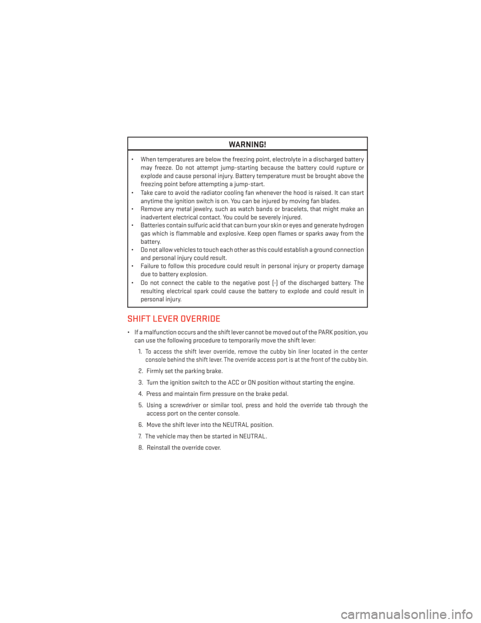
WARNING!
• When temperatures are below the freezing point, electrolyte in a discharged batterymay freeze. Do not attempt jump-starting because the battery could rupture or
explode and cause personal injury. Battery temperature must be brought above the
freezing point before attempting a jump-start.
• Take care to avoid the radiator cooling fan whenever the hood is raised. It can start anytime the ignition switch is on. You can be injured by moving fan blades.
• Remove any metal jewelry, such as watch bands or bracelets, that might make an
inadvertent electrical contact. You could be severely injured.
• Batteries contain sulfuric acid that can burn your skin or eyes and generate hydrogen
gas which is flammable and explosive. Keep open flames or sparks away from the
battery.
• Do not allow vehicles to touch each other as this could establish a ground connection
and personal injury could result.
• Failure to follow this procedure could result in personal injury or property damage
due to battery explosion.
• Do not connect the cable to the negative post (-) of the discharged battery. The resulting electrical spark could cause the battery to explode and could result in
personal injury.
SHIFT LEVER OVERRIDE
• If a malfunction occurs and the shift lever cannot be moved out of the PARK position, youcan use the following procedure to temporarily move the shift lever:
1.
To access the shift lever override, remove the cubby bin liner located in the center
console behind the shift lever. The override access port is at the front of the cubby bin.
2. Firmly set the parking brake.
3. Turn the ignition switch to the ACC or ON position without starting the engine.
4. Press and maintain firm pressure on the brake pedal.
5. Using a screwdriver or similar tool, press and hold the override tab through the access port on the center console.
6. Move the shift lever into the NEUTRAL position.
7. The vehicle may then be started in NEUTRAL.
8. Reinstall the override cover.
WHAT TO DO IN EMERGENCIES
89
Page 94 of 124
EVENT DATA RECORDER (EDR)
This vehicle is equipped with an Event Data Recorder (EDR). The main purpose of an EDR is
to record, in certain crash or near crash-like situations, such as an air bag deployment or
hitting a road obstacle, data that will assist in understanding how a vehicle’s systems
performed. The EDR is designed to record data related to vehicle dynamics and safety
systems for a short period of time, typically 30 seconds or less. The EDR in this vehicle is
designed to record such data as:
• How various systems in your vehicle were operating.
• Whether or not the driver and passenger safety belts were buckled/fastened.
• How far (if at all) the driver was depressing the accelerator and/or brake pedal.
• How fast the vehicle was traveling.
These data can help provide a better understanding of the circumstances in which crashes
and injuries occur.
NOTE:
EDR data is recorded by your vehicle only if a non-trivial crash situation occurs; no data is
recorded by the EDR under normal driving conditions and no personal data (e.g. name,
gender, age, and crash location) is recorded. However, other parties, such as law enforce-
ment, could combine the EDR data with the type of personally identifying data routinely
acquired during a crash investigation.
To read data recorded by an EDR, special equipment is required, and access to the vehicle
or the EDR is needed. In addition to the vehicle manufacturer, other parties such as law
enforcement, that have the special equipment, can read the information if they have
access to the vehicle or the EDR.
WHAT TO DO IN EMERGENCIES
92
Page 99 of 124
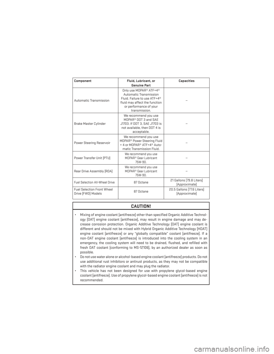
ComponentFluid, Lubricant, or
Genuine Part Capacities
Automatic Transmission Only use MOPAR® ATF+4®
Automatic Transmission
Fluid. Failure to use ATF+4®
fluid may affect the function or performance of your transmission. —
Brake Master Cylinder We recommend you use
MOPAR® DOT 3 and SAE
J1703. If DOT 3, SAE J1703 is not available, then DOT 4 is acceptable. —
Power Steering Reservoir We recommend you use
MOPAR® Power Steering Fluid + 4 or MOPAR® ATF+4® Auto- matic Transmission Fluid. —
Power Transfer Unit (PTU)
We recommend you use MOPAR® Gear Lubricant 75W-90.—
Rear Drive Assembly (RDA)
We recommend you use MOPAR® Gear Lubricant 75W-90.—
Fuel Selection All-Wheel Drive87 Octane 21 Gallons (79.8 Liters)
(Approximate)
Fuel Selection Front Wheel
Drive (FWD) Models 87 Octane20.5 Gallons (77.6 Liters)
(Approximate)
CAUTION!
• Mixing of engine coolant (antifreeze) other than specified Organic Additive Technol-
ogy (OAT) engine coolant (antifreeze), may result in engine damage and may de-
crease corrosion protection. Organic Additive Technology (OAT) engine coolant is
different and should not be mixed with Hybrid Organic Additive Technology (HOAT)
engine coolant (antifreeze) or any “globally compatible” coolant (antifreeze). If a
non-OAT engine coolant (antifreeze) is introduced into the cooling system in an
emergency, the cooling system will need to be drained, flushed, and refilled with
fresh OAT coolant (conforming to MS-12106), by an authorized dealer as soon as
possible.
• Do not use water alone or alcohol-based engine coolant (antifreeze) products. Do not
use additional rust inhibitors or antirust products, as they may not be compatible
with the radiator engine coolant and may plug the radiator.
• This vehicle has not been designed for use with propylene glycol-based engine
coolant (antifreeze). Use of propylene glycol-based engine coolant (antifreeze) is not
recommended.
MAINTAINING YOUR VEHICLE
97
Page 101 of 124
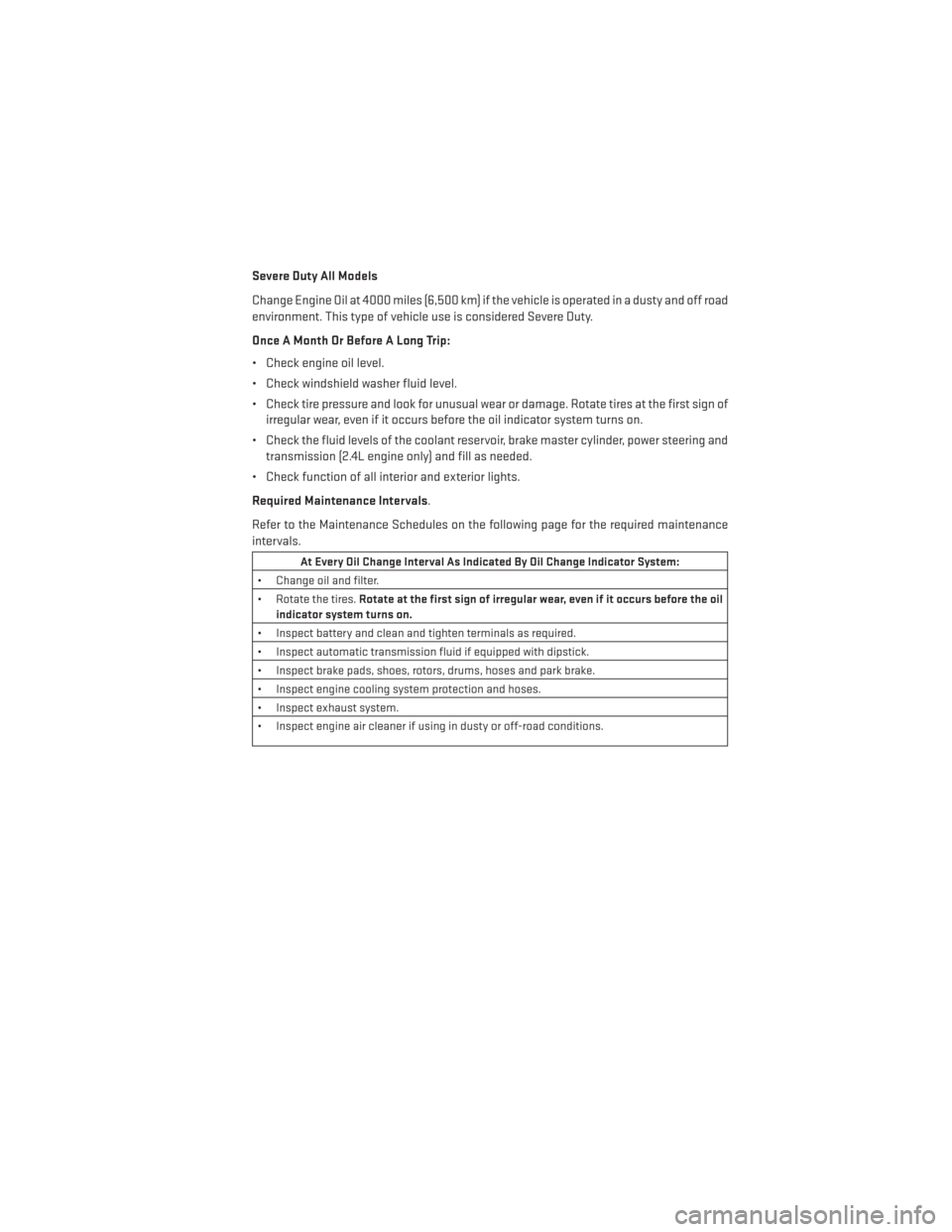
Severe Duty All Models
Change Engine Oil at 4000 miles (6,500 km) if the vehicle is operated in a dusty and off road
environment. This type of vehicle use is considered Severe Duty.
Once A Month Or Before A Long Trip:
• Check engine oil level.
• Check windshield washer fluid level.
• Check tire pressure and look for unusual wear or damage. Rotate tires at the first sign ofirregular wear, even if it occurs before the oil indicator system turns on.
• Check the fluid levels of the coolant reservoir, brake master cylinder, power steering and transmission (2.4L engine only) and fill as needed.
• Check function of all interior and exterior lights.
Required Maintenance Intervals.
Refer to the Maintenance Schedules on the following page for the required maintenance
intervals.
At Every Oil Change Interval As Indicated By Oil Change Indicator System:
• Change oil and filter.
• Rotate the tires. Rotate at the first sign of irregular wear, even if it occurs before the oil
indicator system turns on.
• Inspect battery and clean and tighten terminals as required.
• Inspect automatic transmission fluid if equipped with dipstick.
• Inspect brake pads, shoes, rotors, drums, hoses and park brake.
• Inspect engine cooling system protection and hoses.
• Inspect exhaust system.
• Inspect engine air cleaner if using in dusty or off-road conditions.
MAINTAINING YOUR VEHICLE
99
Page 102 of 124
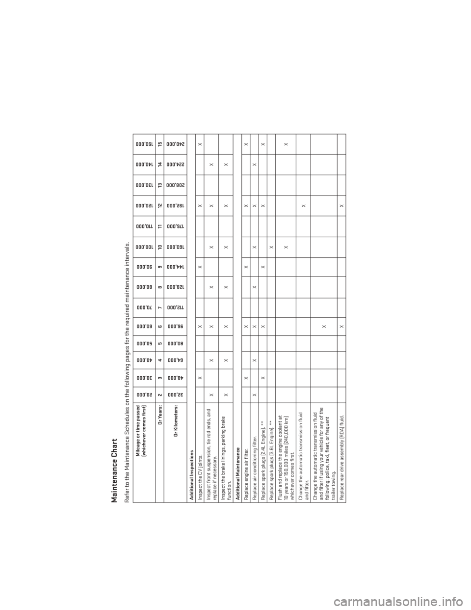
Maintenance ChartRefer to the Maintenance Schedules on the following pages for the required maintenance intervals.
Mileage or time passed
(whichever comes first)
20,000
30,000
40,000
50,000
60,000
70,000
80,000 90,000
100,000
110,000
120,000 130,000
140,000
150,000
Or Years: 2 3 4 5 6 7 8 9 10 11 12 13 14 15
Or Kilometers:
32,000
48,000
64,000
80,000
96,000
112,000
128,000 144,000
160,000
176,000
192,000
208,000
224,000
240,000
Additional Inspections
Inspect the CV joints. X X X X X
Inspect front suspension, tie rod ends, and
replace if necessary. XXX X X X X
Inspect the brake linings, parking brake
function. XXX X X X X
Additional Maintenance
Replace engine air filter. X X X X X
Replace air conditioning filter. X X X X X X X
Replace spark plugs (2.4L Engine). ** X X X X X
Replace spark plugs (3.6L Engine). ** X
Flush and replace the engine coolant at
10 years or 150,000 miles (240,000 km)
whichever comes first. XX
Change the automatic transmission fluid
and filter. X
Change the automatic transmission fluid
and filter if using your vehicle for any of the
following: police, taxi, fleet, or frequent
trailer towing. X
Replace rear drive assembly (RDA) fluid. X X
MAINTAINING YOUR VEHICLE
100
Page 106 of 124
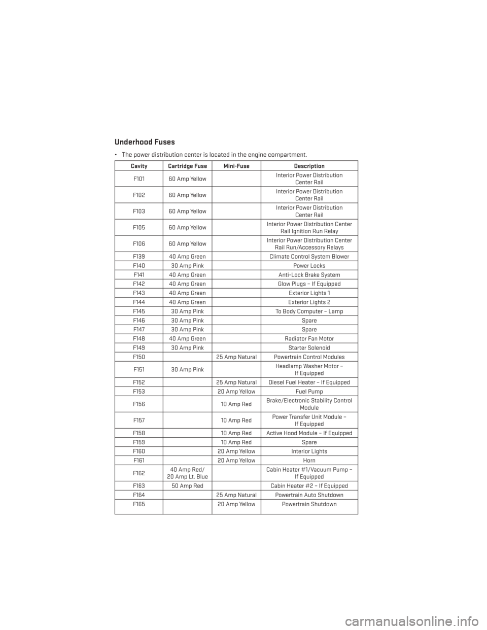
Underhood Fuses
• The power distribution center is located in the engine compartment.
Cavity Cartridge Fuse Mini-FuseDescription
F101 60 Amp Yellow Interior Power Distribution
Center Rail
F102 60 Amp Yellow Interior Power Distribution
Center Rail
F103 60 Amp Yellow Interior Power Distribution
Center Rail
F105 60 Amp Yellow Interior Power Distribution Center
Rail Ignition Run Relay
F106 60 Amp Yellow Interior Power Distribution Center
Rail Run/Accessory Relays
F139 40 Amp Green Climate Control System Blower
F140 30 Amp Pink Power Locks
F141 40 Amp Green Anti-Lock Brake System
F142 40 Amp Green Glow Plugs – If Equipped
F143 40 Amp Green Exterior Lights 1
F144 40 Amp Green Exterior Lights 2
F145 30 Amp Pink To Body Computer – Lamp
F146 30 Amp Pink Spare
F147 30 Amp Pink Spare
F148 40 Amp Green Radiator Fan Motor
F149 30 Amp Pink Starter Solenoid
F150 25 Amp Natural Powertrain Control Modules
F151 30 Amp Pink Headlamp Washer Motor –
If Equipped
F152 25 Amp Natural Diesel Fuel Heater – If Equipped
F153 20 Amp YellowFuel Pump
F156 10 Amp RedBrake/Electronic Stability Control
Module
F157 10 Amp RedPower Transfer Unit Module –
If Equipped
F158 10 Amp Red Active Hood Module – If Equipped
F159 10 Amp RedSpare
F160 20 Amp YellowInterior Lights
F161 20 Amp Yellow Horn
F162 40 Amp Red/
20 Amp Lt. Blue Cabin Heater #1/Vacuum Pump –
If Equipped
F163 50 Amp Red Cabin Heater #2 – If Equipped
F164 25 Amp Natural Powertrain Auto Shutdown
F165 20 Amp Yellow Powertrain Shutdown
MAINTAINING YOUR VEHICLE
104