Battery DODGE JOURNEY 2015 1.G Service Manual
[x] Cancel search | Manufacturer: DODGE, Model Year: 2015, Model line: JOURNEY, Model: DODGE JOURNEY 2015 1.GPages: 648
Page 591 of 648
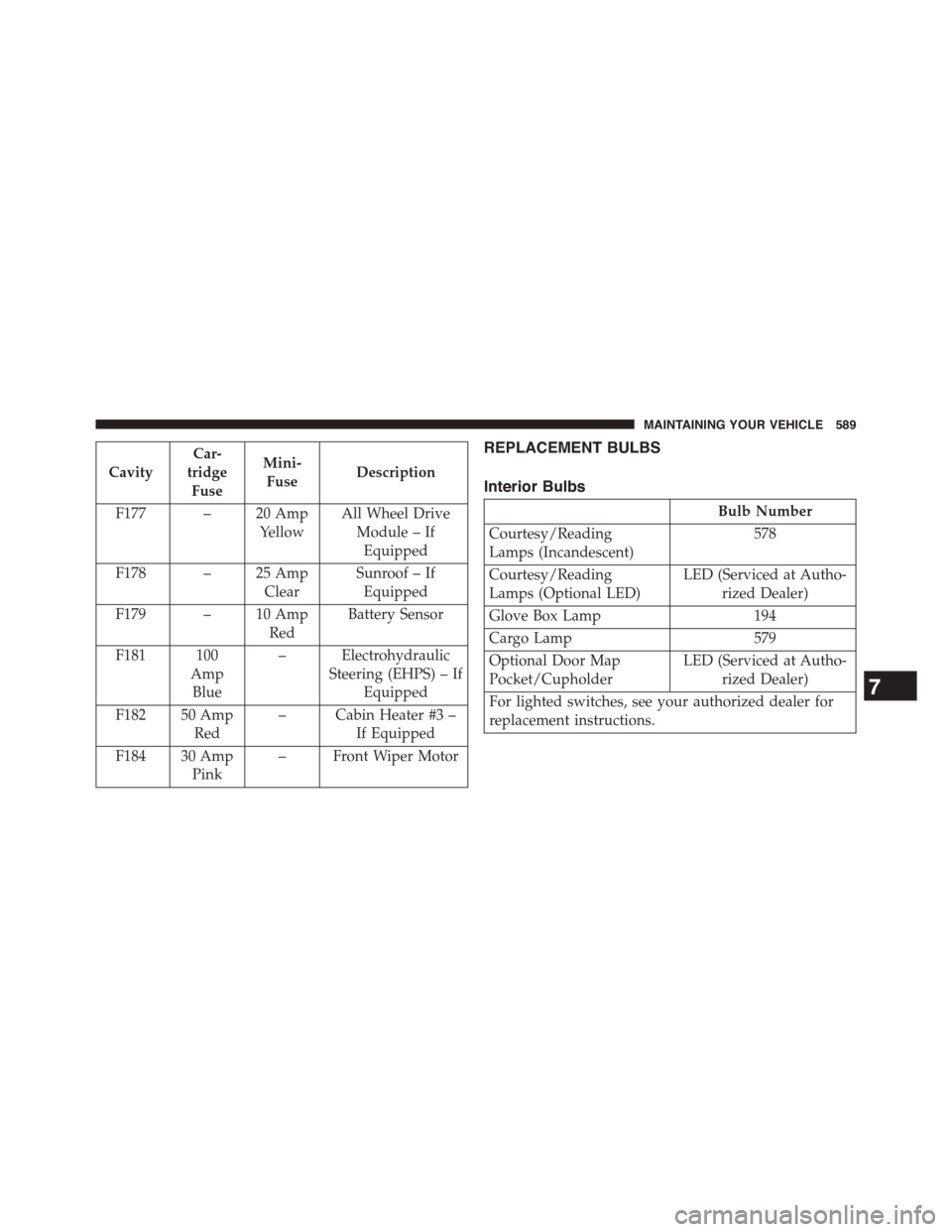
Cavity
Car-
tridge
Fuse
Mini-
FuseDescription
F177 – 20 Amp
Yellow
All Wheel Drive
Module – If
Equipped
F178 – 25 Amp
Clear
Sunroof – If
Equipped
F179 – 10 Amp
Red
Battery Sensor
F181 100
Amp
Blue
– Electrohydraulic
Steering (EHPS) – If
Equipped
F182 50 Amp
Red
– Cabin Heater #3 –
If Equipped
F184 30 Amp
Pink
– Front Wiper Motor
REPLACEMENT BULBS
Interior Bulbs
Bulb Number
Courtesy/Reading
Lamps (Incandescent)
578
Courtesy/Reading
Lamps (Optional LED)
LED (Serviced at Autho-
rized Dealer)
Glove Box Lamp 194
Cargo Lamp 579
Optional Door Map
Pocket/Cupholder
LED (Serviced at Autho-
rized Dealer)
For lighted switches, see your authorized dealer for
replacement instructions.
7
MAINTAINING YOUR VEHICLE 589
Page 607 of 648
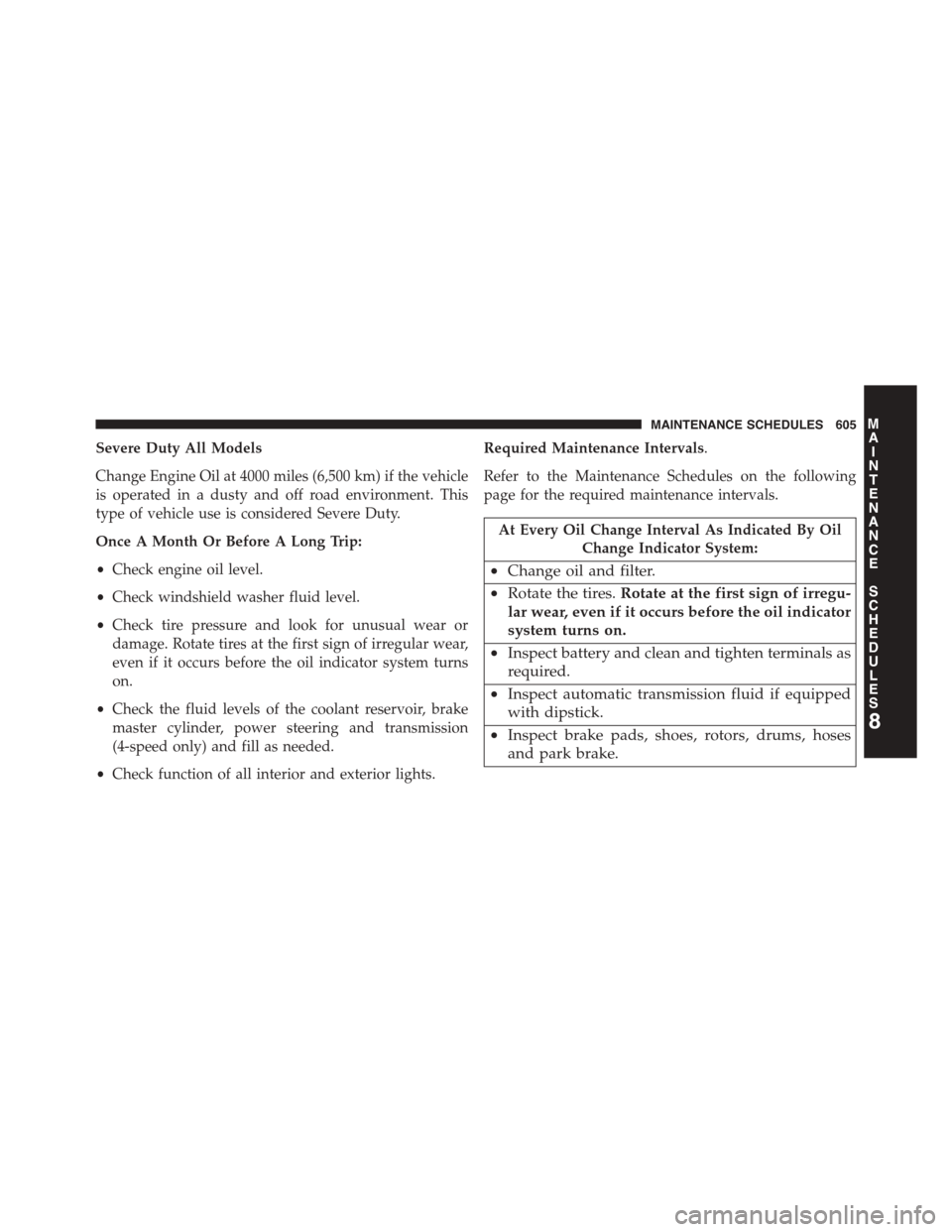
Severe Duty All Models
Change Engine Oil at 4000 miles (6,500 km) if the vehicle
is operated in a dusty and off road environment. This
type of vehicle use is considered Severe Duty.
Once A Month Or Before A Long Trip:
•Check engine oil level.
•Check windshield washer fluid level.
•Check tire pressure and look for unusual wear or
damage. Rotate tires at the first sign of irregular wear,
even if it occurs before the oil indicator system turns
on.
•Check the fluid levels of the coolant reservoir, brake
master cylinder, power steering and transmission
(4-speed only) and fill as needed.
•Check function of all interior and exterior lights.
Required Maintenance Intervals.
Refer to the Maintenance Schedules on the following
page for the required maintenance intervals.
At Every Oil Change Interval As Indicated By Oil
Change Indicator System:
•Change oil and filter.
•Rotate the tires.Rotate at the first sign of irregu-
lar wear, even if it occurs before the oil indicator
system turns on.
•Inspect battery and clean and tighten terminals as
required.
•Inspect automatic transmission fluid if equipped
with dipstick.
•Inspect brake pads, shoes, rotors, drums, hoses
and park brake.
8
MAINTENANCE
SCHEDULES
MAINTENANCE SCHEDULES 605
Page 625 of 648
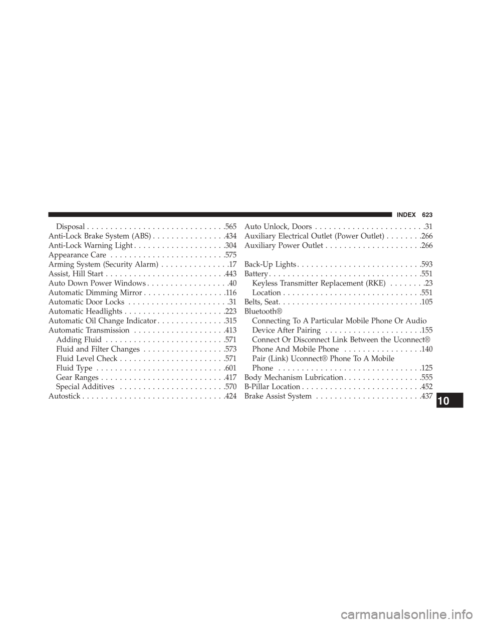
Disposal..............................565
Anti-Lock Brake System (ABS)................434
Anti-Lock Warning Light....................304
Appearance Care.........................575
Arming System (Security Alarm)...............17
Assist, Hill Start..........................443
Auto Down Power Windows..................40
Automatic Dimming Mirror..................116
Automatic Door Locks......................31
Automatic Headlights......................223
Automatic Oil Change Indicator...............315
Automatic Transmission....................413
Adding Fluid..........................571
Fluid and Filter Changes..................573
Fluid Level Check.......................571
Fluid Type............................601
Gear Ranges...........................417
Special Additives.......................570
Autostick...............................424
Auto Unlock, Doors........................31
Auxiliary Electrical Outlet (Power Outlet)........266
Auxiliary Power Outlet.....................266
Back-Up Lights...........................593
Battery.................................551
Keyless Transmitter Replacement (RKE)........23
Location..............................551
Belts, Seat...............................105
Bluetooth®
Connecting To A Particular Mobile Phone Or Audio
Device After Pairing.....................155
Connect Or Disconnect Link Between the Uconnect®
Phone And Mobile Phone.................140
Pair (Link) Uconnect® Phone To A Mobile
Phone...............................125
Body Mechanism Lubrication.................555
B-Pillar Location..........................452
Brake Assist System.......................43710
INDEX 623
Page 636 of 648
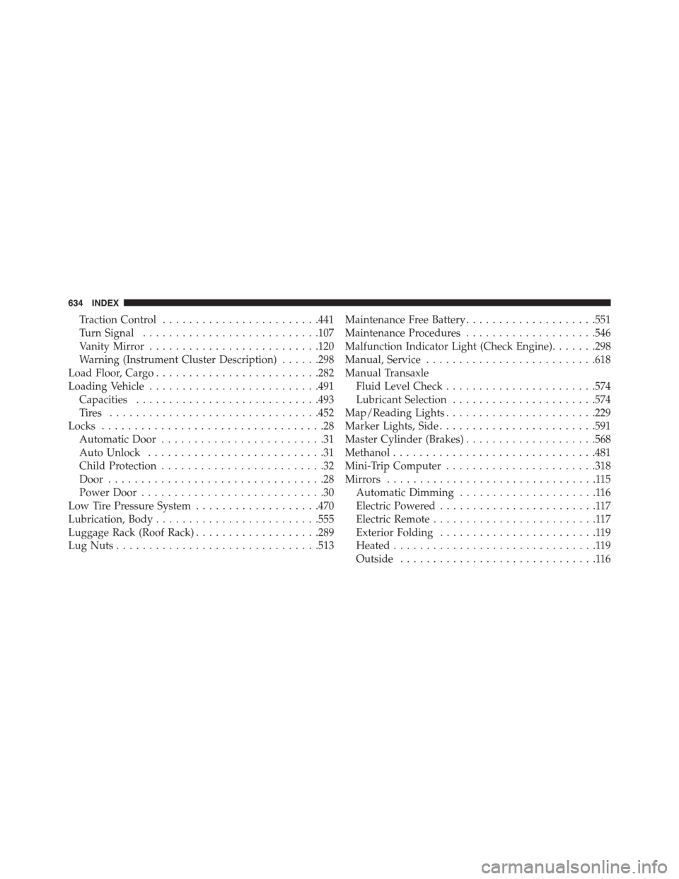
Traction Control........................441
Turn Signal...........................107
Vanity Mirror..........................120
Warning (Instrument Cluster Description)......298
Load Floor, Cargo.........................282
Loading Vehicle..........................491
Capacities............................493
Ti re s . . . . . . . . . . . . . . . . . . . . . . . . . . . . . . ..452
Locks..................................28
Automatic Door.........................31
Auto Unlock...........................31
Child Protection.........................32
Door.................................28
Power Door............................30
Low Tire Pressure System...................470
Lubrication, Body.........................555
Luggage Rack (Roof Rack)...................289
Lug Nuts...............................513
Maintenance Free Battery....................551
Maintenance Procedures....................546
Malfunction Indicator Light (Check Engine).......298
Manual, Service..........................618
Manual Transaxle
Fluid Level Check.......................574
Lubricant Selection......................574
Map/Reading Lights.......................229
Marker Lights, Side........................591
Master Cylinder (Brakes)....................568
Methanol...............................481
Mini-Trip Computer.......................318
Mirrors................................115
Automatic Dimming.....................116
Electric Powered........................117
Electric Remote.........................117
Exterior Folding........................119
Heated...............................119
Outside..............................116
634 INDEX
Page 644 of 648
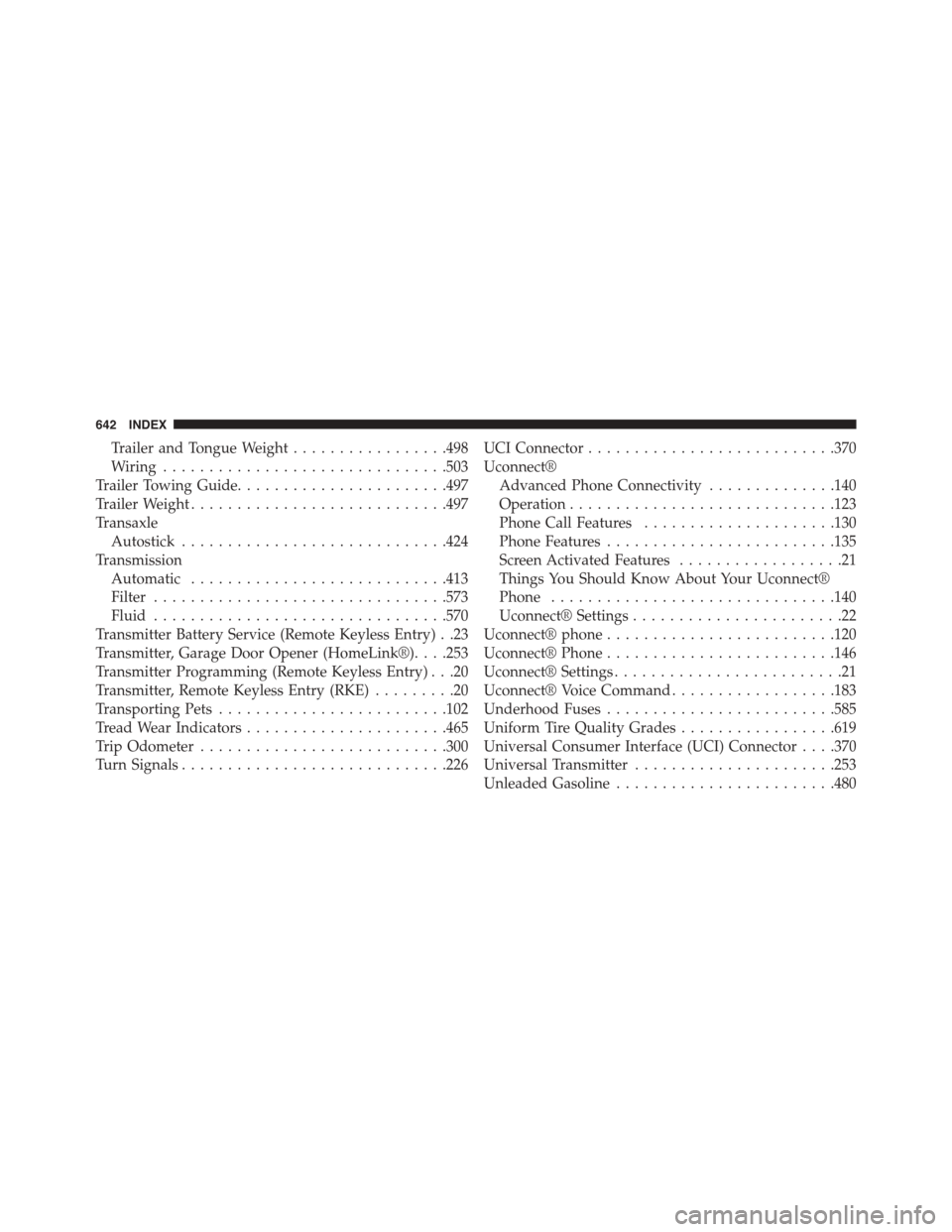
Trailer and Tongue Weight.................498
Wiring...............................503
Trailer Towing Guide.......................497
Trailer Weight............................497
Transaxle
Autostick.............................424
Transmission
Automatic............................413
Filter................................573
Fluid................................570
Transmitter Battery Service (Remote Keyless Entry) . .23
Transmitter, Garage Door Opener (HomeLink®). . . .253
Transmitter Programming (Remote Keyless Entry) . . .20
Transmitter, Remote Keyless Entry (RKE).........20
Transporting Pets.........................102
Tread Wear Indicators......................465
Trip Odometer...........................300
Turn Signals.............................226
UCI Connector...........................370
Uconnect®
Advanced Phone Connectivity..............140
Operation.............................123
Phone Call Features.....................130
Phone Features.........................135
Screen Activated Features..................21
Things You Should Know About Your Uconnect®
Phone...............................140
Uconnect® Settings.......................22
Uconnect® phone.........................120
Uconnect® Phone.........................146
Uconnect® Settings.........................21
Uconnect® Voice Command..................183
Underhood Fuses.........................585
Uniform Tire Quality Grades.................619
Universal Consumer Interface (UCI) Connector . . . .370
Universal Transmitter......................253
Unleaded Gasoline........................480
642 INDEX
Page 647 of 648

INSTALLATION OF RADIO TRANSMITTING
EQUIPMENT
Special design considerations are incorporated into this
vehicle’s electronic system to provide immunity to radio
frequency signals. Mobile two-way radios and telephone
equipment must be installed properly by trained person-
nel. The following must be observed during installation.
The positive power connection should be made directly
to the battery and fused as close to the battery as possible.
The negative power connection should be made to body
sheet metal adjacent to the negative battery connection.
This connection should not be fused.
Antennas for two-way radios should be mounted on the
roof or the rear area of the vehicle. Care should be used
in mounting antennas with magnet bases. Magnets may
affect the accuracy or operation of the compass on
vehicles so equipped.
The antenna cable should be as short as practical and
routed away from the vehicle wiring when possible. Use
only fully shielded coaxial cable.
Carefully match the antenna and cable to the radio to
ensure a low Standing Wave Ratio (SWR).
Mobile radio equipment with output power greater than
normal may require special precautions.
All installations should be checked for possible interfer-
ence between the communications equipment and the
vehicle’s electronic systems.