wheel DODGE JOURNEY 2015 1.G Owner's Manual
[x] Cancel search | Manufacturer: DODGE, Model Year: 2015, Model line: JOURNEY, Model: DODGE JOURNEY 2015 1.GPages: 140, PDF Size: 23.09 MB
Page 100 of 140
12. To stow the winch cable and retainer, fit the assembled jack-handle over the winch
drive nut. Rotate the jack-handle assembly clockwise until you hear the winch
mechanism click three times. It cannot be over tightened.
13. Stow the jack-handle and jack.
14. Check the tire pressure as soon as possible. Adjust the tire pressure as required.
Road Tire Installation
Vehicles Equipped With Wheel Covers
1. Mount the road tire on the axle.
2. To ease the installation process for steel wheels with wheel covers, install two lug nuts
on the mounting studs which are on each side of the valve stem. Install the lug nuts
with the cone shaped end of the nut toward the wheel. Lightly tighten the lug nuts.
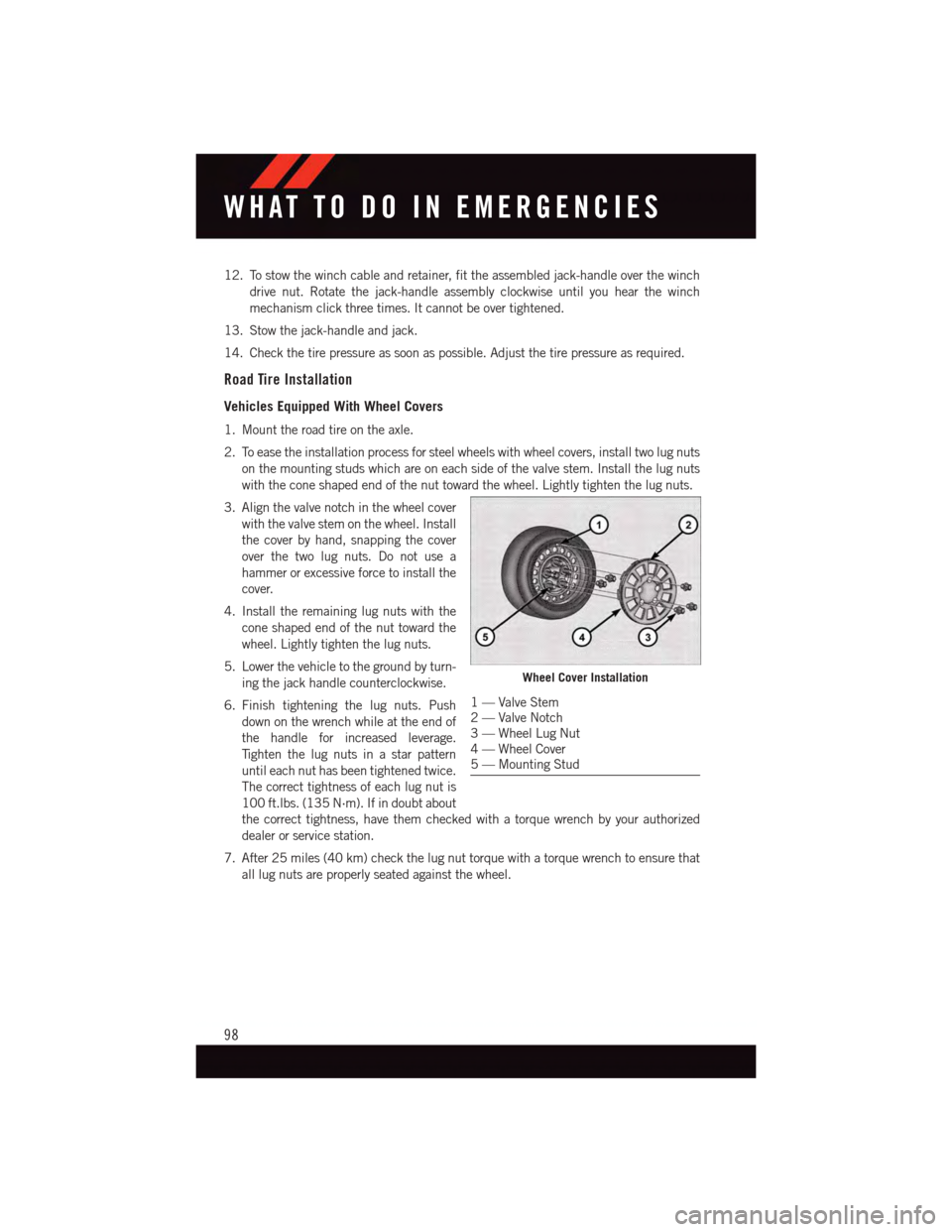
3. Align the valve notch in the wheel cover
with the valve stem on the wheel. Install
the cover by hand, snapping the cover
over the two lug nuts. Do not use a
hammer or excessive force to install the
cover.
4. Install the remaining lug nuts with the
cone shaped end of the nut toward the
wheel. Lightly tighten the lug nuts.
5. Lower the vehicle to the ground by turn-
ing the jack handle counterclockwise.
6. Finish tightening the lug nuts. Push
down on the wrench while at the end of
the handle for increased leverage.
Ti g h t e n t h e l u g n u t s i n a s t a r p a t t e r n
until each nut has been tightened twice.
The correct tightness of each lug nut is
100 ft.lbs. (135 N·m). If in doubt about
the correct tightness, have them checked with a torque wrench by your authorized
dealer or service station.
7. After 25 miles (40 km) check the lug nut torque with a torque wrench to ensure that
all lug nuts are properly seated against the wheel.
Wheel Cover Installation
1—ValveStem2—ValveNotch3—WheelLugNut4—WheelCover5—MountingStud
WHAT TO DO IN EMERGENCIES
98
Page 101 of 140
Vehicles Without Wheel Covers
1. Mount the road tire on the axle.
2. Install the remaining lug nuts with the cone shaped end of the nut toward the wheel.
Lightly tighten the lug nuts.
3. Lower the vehicle to the ground by turning the jack handle counterclockwise.
4. Finish tightening the lug nuts. Push down on the wrench while at the end of the handle
for increased leverage. Tighten the lug nuts in a star pattern until each nut has been
tightened twice. The correct tightness of each lug nut is 100 ft.lbs. (135 N·m). If in
doubt about the correct tightness, have them checked with a torque wrench by your
authorized dealer or service station.
5. After 25 miles (40 km) check the lug nut torque with a torque wrench to ensure that
all lug nuts are properly seated against the wheel.
CAUTION!
•Thewinchmechanismisdesignedforusewiththejack-handleonly.Useofanair
wrench or other power tools is not recommended and they can damage the winch.•Donotattempttoraisethevehiclebyjackingonlocationsotherthanthose
indicated in the Jacking Instructions for this vehicle.
•Besuretomountthesparetirewiththevalvestemfacingoutward.Thevehicle
could be damaged if the spare tire is mounted incorrectly.
WHAT TO DO IN EMERGENCIES
99
Page 102 of 140
WARNING!
•Donotattempttochangeatireonthesideofthevehicleclosetomovingtraffic.
Pull far enough off the road to avoid the danger of being hit when operating the jack
or changing the wheel.
•Beingunderajacked-upvehicleisdangerous.Thevehiclecouldslipoffthejack
and fall on you. You could be crushed. Never put any part of your body under a
vehicle that is on a jack. If you need to get under a raised vehicle, take it to an
authorized service center where it can be raised on a lift.
•Neverstartorruntheenginewhilethevehicleisonajack.
•Thejackisdesignedtobeusedasatoolforchangingtiresonly.Thejackshouldnot
be used to lift the vehicle for service purposes. The vehicle should be jacked on a
firm level surface only. Avoid ice or slippery areas.
•Carefullyfollowthesetirechangingwarningstohelppreventpersonalinjuryor
damage to your vehicle:
•Alwaysparkonafirm,levelsurfaceasfarfromtheedgeoftheroadwayaspossible
before raising the vehicle.
•TurnontheHazardWarningflasher.
•Blockthewheeldiagonallyoppositethewheeltoberaised.
•SettheparkingbrakefirmlyandsetanautomatictransmissioninPARK.
•Donotletanyonesitinthevehiclewhenitisonajack.
•Donotgetunderthevehiclewhenitisonajack.
•Onlyusethejackinthepositionsindicatedandforliftingthisvehicleduringatire
change.
•Ifworkingonorneararoadway,beextremelycarefulofmotortraffic.
•Toassurethatsparetires,flatorinflated,aresecurelystowed,sparesmustbe
stowed with the valve stem facing the ground.
•Raisingthevehiclehigherthannecessarycanmakethevehiclelessstable.Itcould
slip off the jack and hurt someone near it. Raise the vehicle only enough to remove
the tire.
•Toavoidpossiblepersonalinjury,handlethewheelcoverswithcaretoavoidcontact
with any sharp edges.
•Toavoidtheriskofforcingthevehicleoffthejack,donottightenthewheelnuts
fully until the vehicle has been lowered. Failure to follow this warning may result in
personal injury.
•Aloosetireorjack,thrownforwardinacollisionorhardstopcouldendangerthe
occupants of the vehicle. Always stow the jack parts and the spare tire in the places
provided. Have the deflated (flat) tire repaired or replaced immediately.
WHAT TO DO IN EMERGENCIES
100
Page 103 of 140
JUMP-STARTING
•Ifyourvehiclehasadischargedbatteryit
can be jump-started using a set of
jumper cables and a battery in another
vehicle or by using a portable battery
booster pack.
•Jump-startingcanbedangerousifdone
improperly so please follow the proce-
dures in this section carefully.
NOTE:
When using a portable battery booster pack
follow the manufacturer's operating instruc-
tions and precautions.
Preparations For Jump-Start
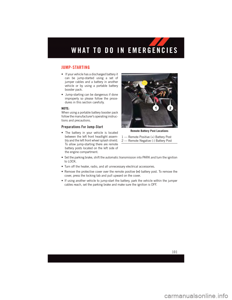
•Thebatteryinyourvehicleislocated
between the left front headlight assem-
bly and the left front wheel splash shield.
To a l l o w j u m p - s t a r t i n g t h e r e a r e r e m o t e
battery posts located on the left side of
the engine compartment.
•Settheparkingbrake,shifttheautomatictransmissionintoPARKandturntheignition
to LOCK.
•Turnofftheheater,radio,andallunnecessaryelectricalaccessories.
•Removetheprotectivecoverovertheremotepositive(+)battery post. To remove the
cover, press the locking tab and pull upward on the cover.
•Ifusinganothervehicletojump-startthebattery,parkthevehiclewithinthejumper
cables reach, set the parking brake and make sure the ignition is OFF.
Remote Battery Post Locations
1—RemotePositive(+)BatteryPost2—RemoteNegative(-)BatteryPost
WHAT TO DO IN EMERGENCIES
101
Page 107 of 140
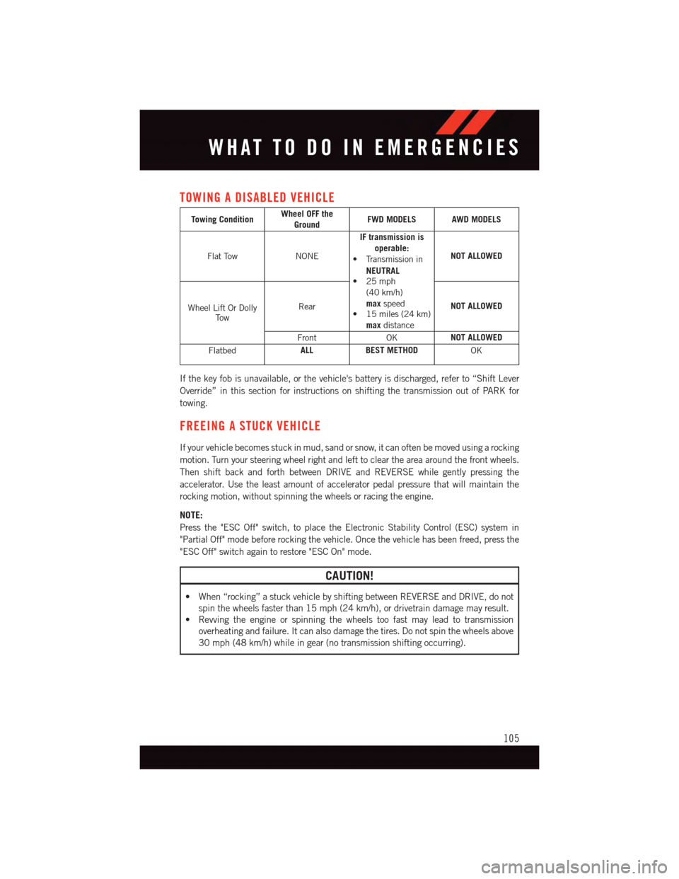
TOWING A DISABLED VEHICLE
Towing ConditionWheel OFF theGroundFWD MODELS AWD MODELS
Flat TowNONE
IF transmission isoperable:•Transmissionin
NEUTRAL•25mph(40 km/h)maxspeed•15miles(24km)maxdistance
NOT ALLOWED
Wheel Lift Or DollyTo w
RearNOT ALLOWED
FrontOKNOT ALLOWED
FlatbedALLBEST METHODOK
If the key fob is unavailable, or the vehicle's battery is discharged, refer to “Shift Lever
Override” in this section for instructions on shifting the transmission out of PARK for
towing.
FREEING A STUCK VEHICLE
If your vehicle becomes stuck in mud, sand or snow, it can often be moved using a rocking
motion. Turn your steering wheel right and left to clear the area around the front wheels.
Then shift back and forth between DRIVE and REVERSE while gently pressing the
accelerator. Use the least amount of accelerator pedal pressure that will maintain the
rocking motion, without spinning the wheels or racing the engine.
NOTE:
Press the "ESC Off" switch, to place the Electronic Stability Control (ESC) system in
"Partial Off" mode before rocking the vehicle. Once the vehicle has been freed, press the
"ESC Off" switch again to restore "ESC On" mode.
CAUTION!
•When“rocking”astuckvehiclebyshiftingbetweenREVERSEandDRIVE,donot
spin the wheels faster than 15 mph (24 km/h), or drivetrain damage may result.
•Revvingtheengineorspinningthewheelstoofastmayleadtotransmission
overheating and failure. It can also damage the tires. Do not spin the wheels above
30 mph (48 km/h) while in gear (no transmission shifting occurring).
WHAT TO DO IN EMERGENCIES
105
Page 108 of 140
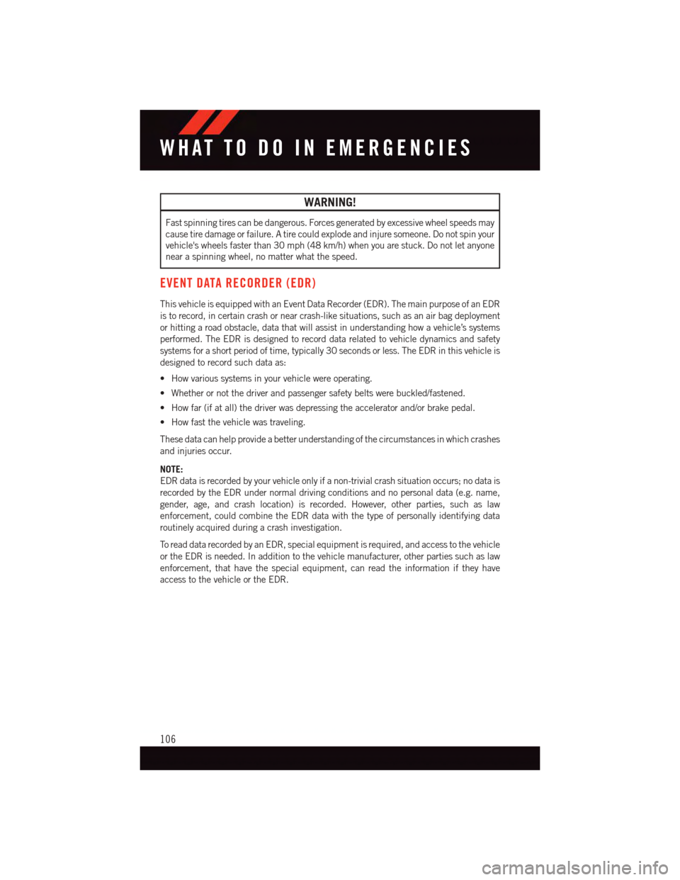
WARNING!
Fast spinning tires can be dangerous. Forces generated by excessive wheel speeds may
cause tire damage or failure. A tire could explode and injure someone. Do not spin your
vehicle's wheels faster than 30 mph (48 km/h) when you are stuck. Do not let anyone
near a spinning wheel, no matter what the speed.
EVENT DATA RECORDER (EDR)
This vehicle is equipped with an Event Data Recorder (EDR). The main purpose of an EDR
is to record, in certain crash or near crash-like situations, such as an air bag deployment
or hitting a road obstacle, data that will assist in understanding how a vehicle’s systems
performed. The EDR is designed to record data related to vehicle dynamics and safety
systems for a short period of time, typically 30 seconds or less. The EDR in this vehicle is
designed to record such data as:
•Howvarioussystemsinyourvehiclewereoperating.
•Whetherornotthedriverandpassengersafetybeltswerebuckled/fastened.
•Howfar(ifatall)thedriverwasdepressingtheacceleratorand/orbrakepedal.
•Howfastthevehiclewastraveling.
These data can help provide a better understanding of the circumstances in which crashes
and injuries occur.
NOTE:
EDR data is recorded by your vehicle only if a non-trivial crash situation occurs; no data is
recorded by the EDR under normal driving conditions and no personal data (e.g. name,
gender, age, and crash location) is recorded. However, other parties, such as law
enforcement, could combine the EDR data with the type of personally identifying data
routinely acquired during a crash investigation.
To r e a d d a t a r e c o r d e d b y a n E D R , s p e c i a l e q u i p m e n t i s r e q u i r e d , a n d a c c e s s t o t h e v e h i c l e
or the EDR is needed. In addition to the vehicle manufacturer, other parties such as law
enforcement, that have the special equipment, can read the information if they have
access to the vehicle or the EDR.
WHAT TO DO IN EMERGENCIES
106
Page 114 of 140
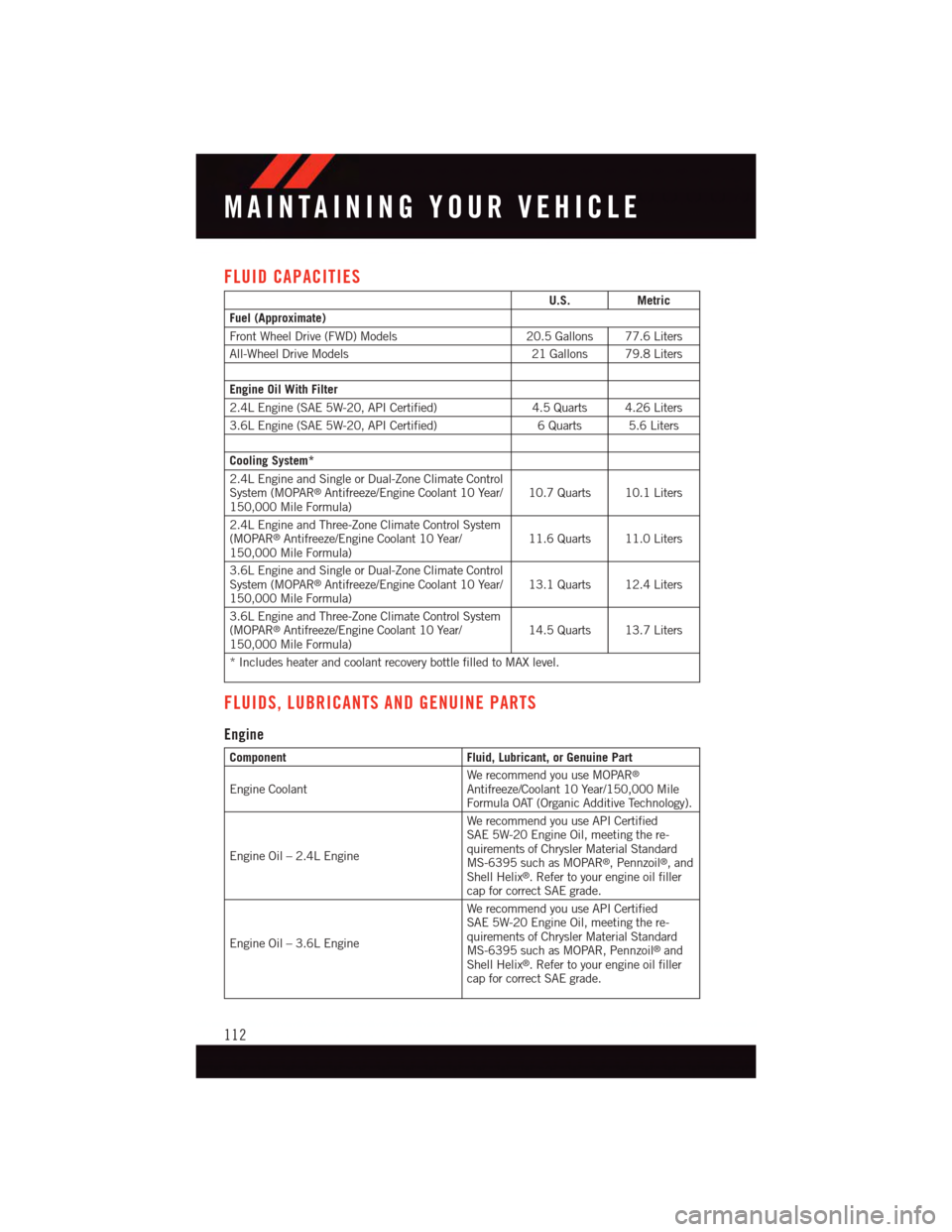
FLUID CAPACITIES
U.S.Metric
Fuel (Approximate)
Front Wheel Drive (FWD) Models20.5 Gallons 77.6 Liters
All-Wheel Drive Models21 Gallons 79.8 Liters
Engine Oil With Filter
2.4L Engine (SAE 5W-20, API Certified)4.5 Quarts 4.26 Liters
3.6L Engine (SAE 5W-20, API Certified)6Quarts 5.6Liters
Cooling System*
2.4L Engine and Single or Dual-Zone Climate ControlSystem (MOPAR®Antifreeze/Engine Coolant 10 Year/150,000 Mile Formula)10.7 Quarts 10.1 Liters
2.4L Engine and Three-Zone Climate Control System(MOPAR®Antifreeze/Engine Coolant 10 Year/150,000 Mile Formula)11.6 Quarts 11.0 Liters
3.6L Engine and Single or Dual-Zone Climate ControlSystem (MOPAR®Antifreeze/Engine Coolant 10 Year/150,000 Mile Formula)13.1 Quarts 12.4 Liters
3.6L Engine and Three-Zone Climate Control System(MOPAR®Antifreeze/Engine Coolant 10 Year/150,000 Mile Formula)14.5 Quarts 13.7 Liters
*IncludesheaterandcoolantrecoverybottlefilledtoMAXlevel.
FLUIDS, LUBRICANTS AND GENUINE PARTS
Engine
ComponentFluid, Lubricant, or Genuine Part
Engine CoolantWe recommend you use MOPAR®
Antifreeze/Coolant 10 Year/150,000 MileFormula OAT (Organic Additive Technology).
Engine Oil – 2.4L Engine
We recommend you use API CertifiedSAE 5W-20 Engine Oil, meeting the re-quirements of Chrysler Material StandardMS-6395 such as MOPAR®,Pennzoil®,andShell Helix®.Refertoyourengineoilfillercap for correct SAE grade.
Engine Oil – 3.6L Engine
We recommend you use API CertifiedSAE 5W-20 Engine Oil, meeting the re-quirements of Chrysler Material StandardMS-6395 such as MOPAR, Pennzoil®andShell Helix®.Refertoyourengineoilfillercap for correct SAE grade.
MAINTAINING YOUR VEHICLE
112
Page 121 of 140
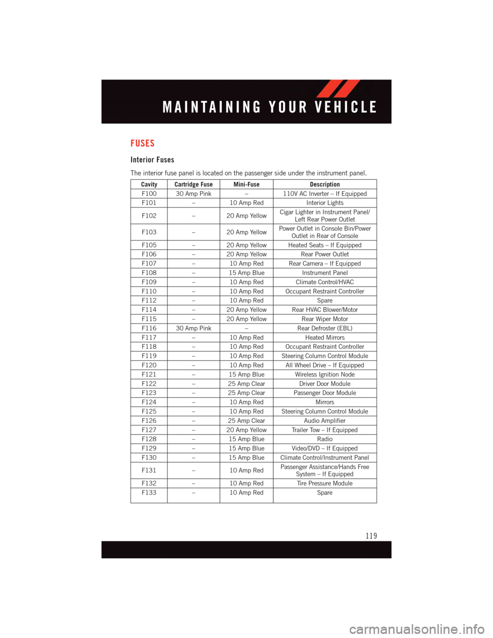
FUSES
Interior Fuses
The interior fuse panel is located on the passenger side under the instrument panel.
Cavity Cartridge Fuse Mini-FuseDescription
F100 30 Amp Pink–110V AC Inverter – If Equipped
F101–10 Amp RedInterior Lights
F102–20AmpYellowCigar Lighter in Instrument Panel/Left Rear Power Outlet
F103–20AmpYellowPower Outlet in Console Bin/PowerOutlet in Rear of Console
F105–20AmpYellowHeatedSeats–IfEquipped
F106–20AmpYellowRear Power Outlet
F107–10 Amp Red Rear Camera – If Equipped
F108–15 Amp BlueInstrument Panel
F109–10 Amp RedClimate Control/HVAC
F110–10 Amp Red Occupant Restraint Controller
F112–10 Amp RedSpare
F114–20AmpYellowRearHVACBlower/Motor
F115–20AmpYellowRear Wiper Motor
F116 30 Amp Pink–Rear Defroster (EBL)
F117–10 Amp RedHeated Mirrors
F118–10 Amp Red Occupant Restraint Controller
F119–10 Amp Red Steering Column Control Module
F120–10 Amp Red All Wheel Drive – If Equipped
F121–15 Amp Blue Wireless Ignition Node
F122–25 Amp ClearDriver Door Module
F123–25 Amp Clear Passenger Door Module
F124–10 Amp RedMirrors
F125–10 Amp Red Steering Column Control Module
F126–25 Amp ClearAudio Amplifier
F127–20AmpYellowTrailerTow–IfEquipped
F128–15 Amp BlueRadio
F129–15 Amp Blue Video/DVD – If Equipped
F130–15 Amp Blue Climate Control/Instrument Panel
F131–10 Amp RedPassenger Assistance/Hands FreeSystem – If Equipped
F132–10 Amp RedTi r e P r e s s u r e M o d u l e
F133–10 Amp RedSpare
MAINTAINING YOUR VEHICLE
119
Page 123 of 140
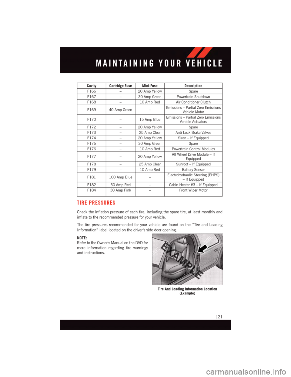
Cavity Cartridge Fuse Mini-FuseDescription
F166–20AmpYellowSpare
F167–30AmpGreenPowertrainShutdown
F168–10AmpRedAirConditionerClutch
F169 40 Amp Green –Emissions – Partial Zero EmissionsVehicle Motor
F170–15AmpBlueEmissions – Partial Zero EmissionsVehicle Actuators
F172–20AmpYellowSpare
F173–25AmpClearAntiLockBrakeValves
F174–20AmpYellowSiren–IfEquipped
F175–30AmpGreenSpare
F176–10AmpRedPowertrainControlModules
F177–20AmpYellowAll Wheel Drive Module – IfEquipped
F178–25AmpClearSunroof–IfEquipped
F179–10AmpRedBattery Sensor
F181 100 Amp Blue –Electrohydraulic Steering (EHPS)–IfEquipped
F182 50 Amp Red – Cabin Heater #3 – If Equipped
F184 30 Amp Pink –Front Wiper Motor
TIRE PRESSURES
Check the inflation pressure of each tire, including the spare tire, at least monthly and
inflate to the recommended pressure for your vehicle.
The tire pressures recommended for your vehicle are found on the “Tire and Loading
Information” label located on the driver’s side door opening.
NOTE:
Refer to the Owner's Manual on the DVD for
more information regarding tire warnings
and instructions.
Tire And Loading Information Location(Example)
MAINTAINING YOUR VEHICLE
121
Page 124 of 140
WARNING!
•Overloadingofyourtiresisdangerous.Overloadingcancausetirefailure,affect
vehicle handling, and increase your stopping distance. Use tires of the recom-
mended load capacity for your vehicle. Never overload them.
•Improperlyinflatedtiresaredangerousandcancausecollisions.Under-inflation
increases tire flexing and can result in over-heating and tire failure. Over-inflation
reduces a tire’s ability to cushion shock. Objects on the road and chuck holes can
cause damage that results in tire failure. Unequal tire pressures can cause steering
problems. You could lose control of your vehicle. Over-inflated or under-inflated
tires can affect vehicle handling and can fail suddenly, resulting in loss of vehicle
control. Always drive with each tire inflated to the recommended cold tire inflation
pressure.
SPARE TIRES — IF EQUIPPED
NOTE:
For vehicles equipped with Tire Service Kit instead of a spare tire, please refer to “Tire
Service Kit” in “What To Do In Emergencies” on your DVD for further information.
CAUTION!
Because of the reduced ground clearance, do not take your vehicle through an
automatic car wash with a compact or limited-use temporary spare installed. Damage
to the vehicle may result.
Spare Tire Matching Original Equipped Tire And Wheel — If Equipped
Yo u r v e h i c l e m a y b e e q u i p p e d w i t h a s p a r e t i r e a n d w h e e l e q u i v a l e n t i n l o o k a n d f u n c t i o n
to the original equipment tire and wheel found on the front or rear axle of your vehicle. This
spare tire may be used in the tire rotation for your vehicle. If your vehicle has this option,
refer to an authorized tire dealer for the recommended tire rotation pattern.
Compact Spare Tire — If Equipped
The compact spare is for temporary emergency use only. You can identify if your vehicle
is equipped with a compact spare by looking at the spare tire description on the Tire and
Loading Information Placard located on the driver’s side door opening or on the sidewall
of the tire. Compact spare tire descriptions begin with the letter “T” or “S” preceding the
size designation. Example: T145/80D18 103M.
T, S = Temporary Spare Tire
Since this tire has limited tread life, the original equipment tire should be repaired (or
replaced) and reinstalled on your vehicle at the first opportunity.
MAINTAINING YOUR VEHICLE
122