wheel DODGE JOURNEY 2015 1.G Owner's Manual
[x] Cancel search | Manufacturer: DODGE, Model Year: 2015, Model line: JOURNEY, Model: DODGE JOURNEY 2015 1.GPages: 140, PDF Size: 23.09 MB
Page 73 of 140
Mute (Or Unmute) Microphone During Call
•Duringacall,pressthe“mute”buttononthetouchscreentomuteandunmutethe
call.
Transfer Ongoing Call Between Handset And Vehicle
During an on-going call, press the “Transfer” button on the touchscreen to transfer an
on-going call between handset and vehicle.
Common Phone Commands (Examples)
•“CallJohnSmith”
•“CallJohnSmithmobile”
•“Dial12485551212”
•“CallEmergency”
•“CallTowingAssistance”
•“Redial”
Phonebook
•Uconnect®radios will automatically download your phonebook from your paired
phone, if this feature is supported by your phone. Entries are updated each time that
the phone is connected. If your phone book entries do not appear, check the settings on
your phone. Some phones require you to enable this feature manually.
•Yourphonebookcanbebrowsedonyourradioscreen,buteditingcanonlybedoneon
your phone. To browse, press the “Phone” button on the touchscreen, then the
“Phonebook” button on the touchscreen.
•FavoritephonebookentriescanbesavedasFavoritesforquickeraccess.Favoritesare
shown at the top of your main phone screen.
Voice Command Tips (8.4 And 8.4N Only)
•Usingcompletenames(i.e;CallJohnDoevs.CallJohn)willresultingreatersystem
accuracy.
•Youcan“chain”commandstogetherforfasterresults.Say“CallJohnDoemobile,”for
example.
•Ifyouarelisteningtoavailablevoicecommandoptions,youdonothavetolistentothe
entire list. When you hear the command that you need, press thebutton on the
steering wheel, wait for the beep and say your command.
Changing The Volume
•StartadialoguebypressingthePhonebutton,thensayacommandforexample
-"Help."
•UsetheradioON/OFFVOLUMErotaryknobtoadjustthevolumetoacomfortablelevel
while the Uconnect®system is speaking. Please note the volume setting for Uconnect®
is different than the audio system.
ELECTRONICS
71
Page 74 of 140
NOTE:
To a c c e s s h e l p , p r e s s t h e U c o n n e c t®Phonebutton on the steering wheel and say
"help." Press the display or push eitherorbutton and say "cancel" to cancel
the help session.
Voice Text Reply
•Uconnect®Phone can read or send new text messages on your mobile phone.
•YourmobilephonemustsupportVoiceTextReplyoverBluetooth®to use this feature.
If the Uconnect®Phone determines your mobile phone is not compatible with Voice
Te x t R e p l y m e s s a g i n g o v e r B l u e t o o t h®,the“Messaging”buttonwillbegreyedoutand
the feature will not be available for use.
NOTE:
•For mobile phone compatibility and pairing instructions, please visit
UconnectPhone.com
•Uconnect®Phone Voice Text Reply is only available when the vehicle is not moving.
WARNING!
•Anyvoicecommandedsystemshouldbeusedonlyinsafedrivingconditions
following applicable laws regarding phone use. Your attention should be focused on
safely operating the vehicle. Failure to do so may result in a collision causing you
and others to be severely injured or killed.
•Inanemergency,touseUconnect®Phone, your mobile phone must be:
•turnedon,
•pairedtoUconnect®Phone,
•andhavenetworkcoverage.
Uconnect® VOICE COMMAND (8.4 & 8.4N ONLY)
•IftheUconnect®Voice Commandbutton exists on your steering wheel, then
you have the Voice Command feature.
•TheVoiceCommandfeatureletsyoukeepyourhandsonthesteeringwheel,andyour
eyes on the road.
•WhenyoupresstheVoiceCommandbuttonlocated on the radio faceplate or
steering wheel, you will hear a beep. The beep is your signal to give a command. If you
do not know what commands to say, you can say "help" and the system will provide
options to you. If you ever wish to interrupt the system while it lists options, press the
Voice Command button,listenfortheBEEP,andsayyourcommand.
•Youcan“chain”commandstogetherforfasterresults.Say“PlaytheartistScott
Joplin”, for example.
ELECTRONICS
72
Page 78 of 140
STEERING WHEEL AUDIO CONTROLS
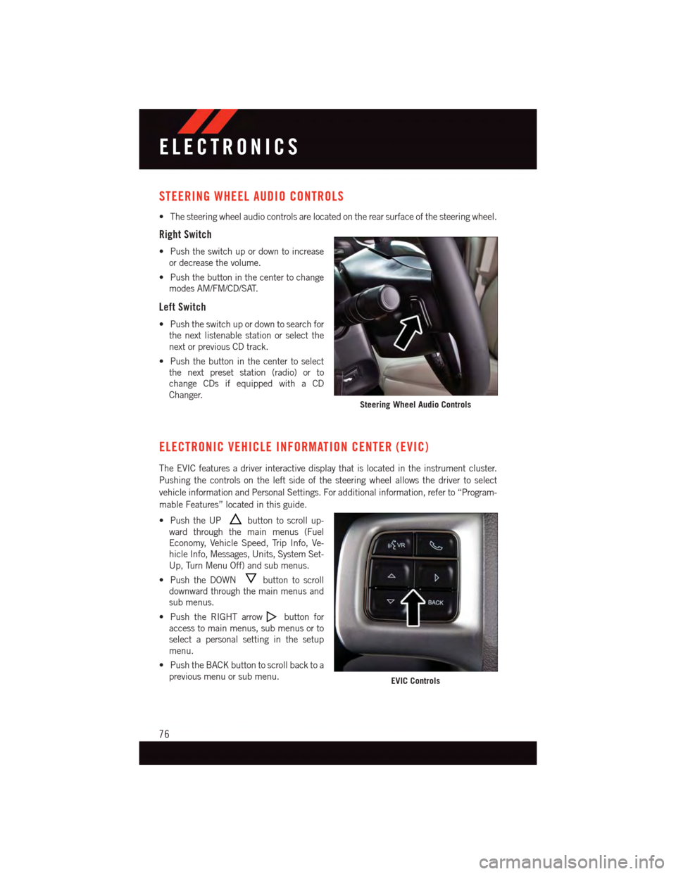
•Thesteeringwheelaudiocontrolsarelocatedontherearsurfaceofthesteeringwheel.
Right Switch
•Pushtheswitchupordowntoincrease
or decrease the volume.
•Pushthebuttoninthecentertochange
modes AM/FM/CD/SAT.
Left Switch
•Pushtheswitchupordowntosearchfor
the next listenable station or select the
next or previous CD track.
•Pushthebuttoninthecentertoselect
the next preset station (radio) or to
change CDs if equipped with a CD
Changer.
ELECTRONIC VEHICLE INFORMATION CENTER (EVIC)
The EVIC features a driver interactive display that is located in the instrument cluster.
Pushing the controls on the left side of the steering wheel allows the driver to select
vehicle information and Personal Settings. For additional information, refer to “Program-
mable Features” located in this guide.
•PushtheUPbutton to scroll up-
ward through the main menus (Fuel
Economy, Vehicle Speed, Trip Info, Ve-
hicle Info, Messages, Units, System Set-
Up, Turn Menu Off) and sub menus.
•PushtheDOWNbutton to scroll
downward through the main menus and
sub menus.
•PushtheRIGHTarrowbutton for
access to main menus, sub menus or to
select a personal setting in the setup
menu.
•PushtheBACKbuttontoscrollbacktoa
previous menu or sub menu.
Steering Wheel Audio Controls
EVIC Controls
ELECTRONICS
76
Page 86 of 140
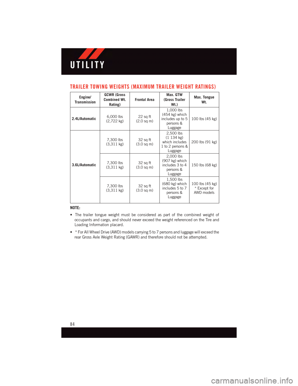
TRAILER TOWING WEIGHTS (MAXIMUM TRAILER WEIGHT RATINGS)
Engine/Transmission
GCWR (GrossCombined Wt.Rating)Frontal AreaMax. GTW(Gross TrailerWt.)
Max. TongueWt.
2.4L/Automatic6,000 lbs(2,722 kg)22 sq ft(2.0 sq m)
1,000 lbs(454 kg) whichincludes up to 5persons &Luggage
100 lbs (45 kg)
3.6L/Automatic
7,300 lbs(3,311 kg)32 sq ft(3.0 sq m)
2,500 lbs(1 134 kg)which includes1to2persons&Luggage
200 lbs (91 kg)
7,300 lbs(3,311 kg)32 sq ft(3.0 sq m)
2,000 lbs(907 kg) whichincludes 3 to 4persons &Luggage
150 lbs (68 kg)
7,300 lbs(3,311 kg)32 sq ft(3.0 sq m)
1,500 lbs(680 kg) whichincludes 5 to 7persons &Luggage
100 lbs (45 kg)*ExceptforAWD models
NOTE:
•Thetrailertongueweightmustbeconsideredaspartofthecombinedweightof
occupants and cargo, and should never exceed the weight referenced on the Tire and
Loading Information placard.
•*ForAllWheelDrive(AWD)modelscarrying5to7personsandluggagewillexceedthe
rear Gross Axle Weight Rating (GAWR) and therefore should not be attempted.
UTILITY
84
Page 87 of 140
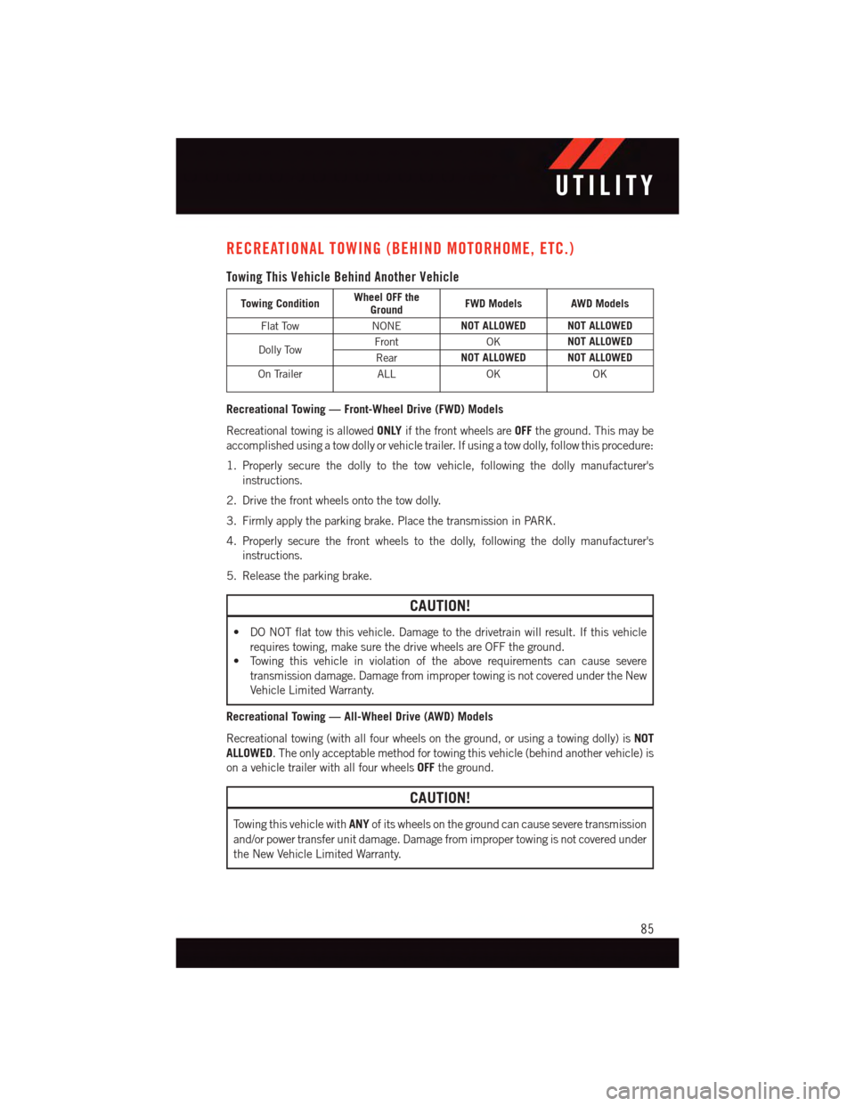
RECREATIONAL TOWING (BEHIND MOTORHOME, ETC.)
Towing This Vehicle Behind Another Vehicle
Towing ConditionWheel OFF theGroundFWD Models AWD Models
Flat TowNONENOT ALLOWED NOT ALLOWED
Dolly TowFrontOKNOT ALLOWED
RearNOT ALLOWED NOT ALLOWED
On TrailerALLOKOK
Recreational Towing — Front-Wheel Drive (FWD) Models
Recreational towing is allowedONLYif the front wheels areOFFthe ground. This may be
accomplished using a tow dolly or vehicle trailer. If using a tow dolly, follow this procedure:
1. Properly secure the dolly to the tow vehicle, following the dolly manufacturer's
instructions.
2. Drive the front wheels onto the tow dolly.
3. Firmly apply the parking brake. Place the transmission in PARK.
4. Properly secure the front wheels to the dolly, following the dolly manufacturer's
instructions.
5. Release the parking brake.
CAUTION!
•DONOTflattowthisvehicle.Damagetothedrivetrainwillresult.Ifthisvehicle
requires towing, make sure the drive wheels are OFF the ground.
•Towingthisvehicleinviolationoftheaboverequirementscancausesevere
transmission damage. Damage from improper towing is not covered under the New
Vehicle Limited Warranty.
Recreational Towing — All-Wheel Drive (AWD) Models
Recreational towing (with all four wheels on the ground, or using a towing dolly) isNOT
ALLOWED.Theonlyacceptablemethodfortowingthisvehicle(behindanothervehicle)is
on a vehicle trailer with all four wheelsOFFthe ground.
CAUTION!
To w i n g t h i s v e h i c l e w i t hANYof its wheels on the ground can cause severe transmission
and/or power transfer unit damage. Damage from improper towing is not covered under
the New Vehicle Limited Warranty.
UTILITY
85
Page 90 of 140
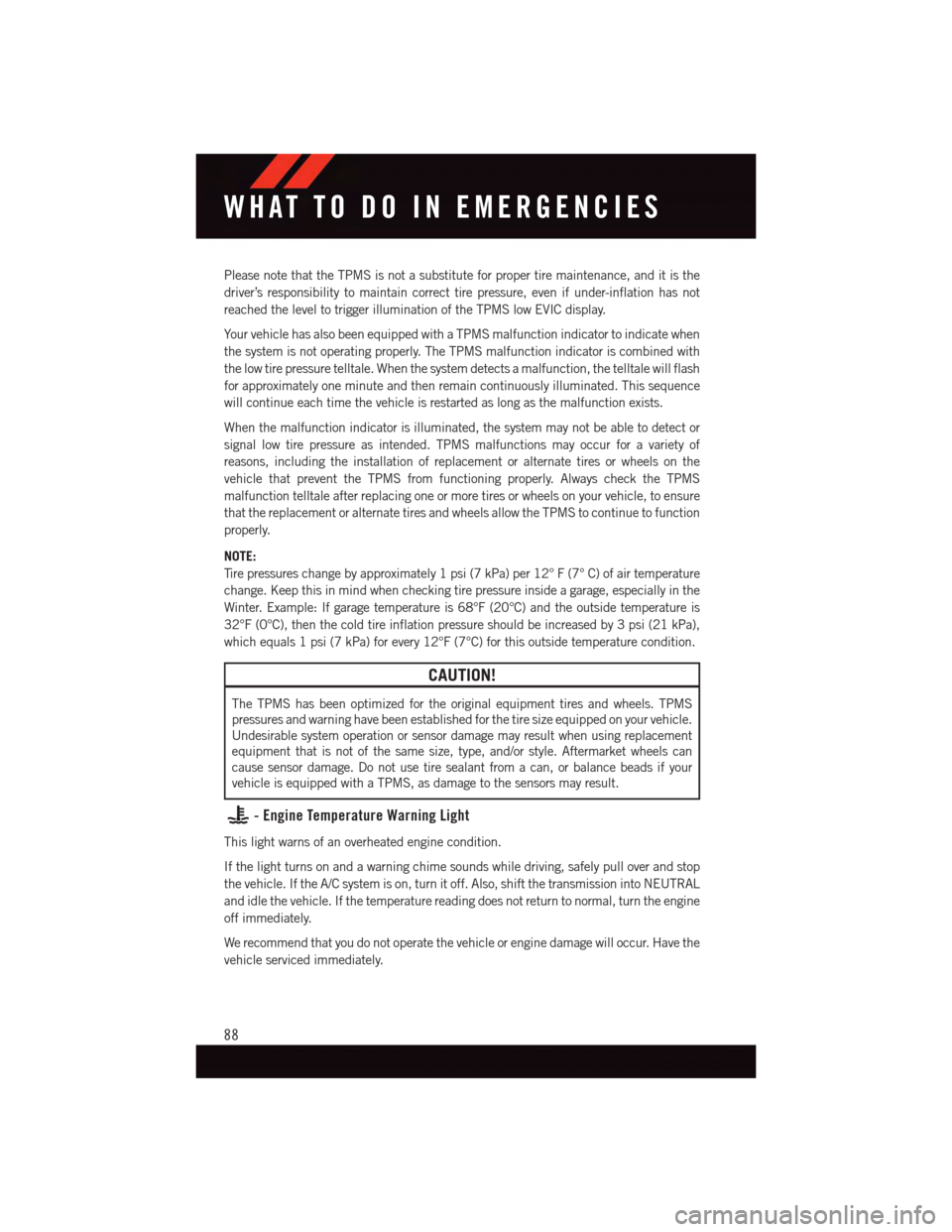
Please note that the TPMS is not a substitute for proper tire maintenance, and it is the
driver’s responsibility to maintain correct tire pressure, even if under-inflation has not
reached the level to trigger illumination of the TPMS low EVIC display.
Yo u r v e h i c l e h a s a l s o b e e n e q u i p p e d w i t h a T P M S m a l f u n c t i o n i n d i c a t o r t o i n d i c a t e w h e n
the system is not operating properly. The TPMS malfunction indicator is combined with
the low tire pressure telltale. When the system detects a malfunction, the telltale will flash
for approximately one minute and then remain continuously illuminated. This sequence
will continue each time the vehicle is restarted as long as the malfunction exists.
When the malfunction indicator is illuminated, the system may not be able to detect or
signal low tire pressure as intended. TPMS malfunctions may occur for a variety of
reasons, including the installation of replacement or alternate tires or wheels on the
vehicle that prevent the TPMS from functioning properly. Always check the TPMS
malfunction telltale after replacing one or more tires or wheels on your vehicle, to ensure
that the replacement or alternate tires and wheels allow the TPMS to continue to function
properly.
NOTE:
Ti r e p r e s s u r e s c h a n g e b y a p p r o x i m a t e l y 1 p s i ( 7 k P a ) p e r 1 2 ° F ( 7 ° C ) o f a i r t e m p e r a t u r e
change. Keep this in mind when checking tire pressure inside a garage, especially in the
Winter. Example: If garage temperature is 68°F (20°C) and the outside temperature is
32°F (0°C), then the cold tire inflation pressure should be increased by 3 psi (21 kPa),
which equals 1 psi (7 kPa) for every 12°F (7°C) for this outside temperature condition.
CAUTION!
The TPMS has been optimized for the original equipment tires and wheels. TPMS
pressures and warning have been established for the tire size equipped on your vehicle.
Undesirable system operation or sensor damage may result when using replacement
equipment that is not of the same size, type, and/or style. Aftermarket wheels can
cause sensor damage. Do not use tire sealant from a can, or balance beads if your
vehicle is equipped with a TPMS, as damage to the sensors may result.
-EngineTemperatureWarningLight
This light warns of an overheated engine condition.
If the light turns on and a warning chime sounds while driving, safely pull over and stop
the vehicle. If the A/C system is on, turn it off. Also, shift the transmission into NEUTRAL
and idle the vehicle. If the temperature reading does not return to normal, turn the engine
off immediately.
We recommend that you do not operate the vehicle or engine damage will occur. Have the
vehicle serviced immediately.
WHAT TO DO IN EMERGENCIES
88
Page 96 of 140
Preparations For Jacking
1. Park the vehicle on a firm, level surface as far from the edge of the roadway as possible.
Avoid icy or slippery areas.
2. Turn on the Hazard Warning flashers.
3. Set the parking brake.
4. Place the shift lever in PARK.
5. Turn OFF the ignition.
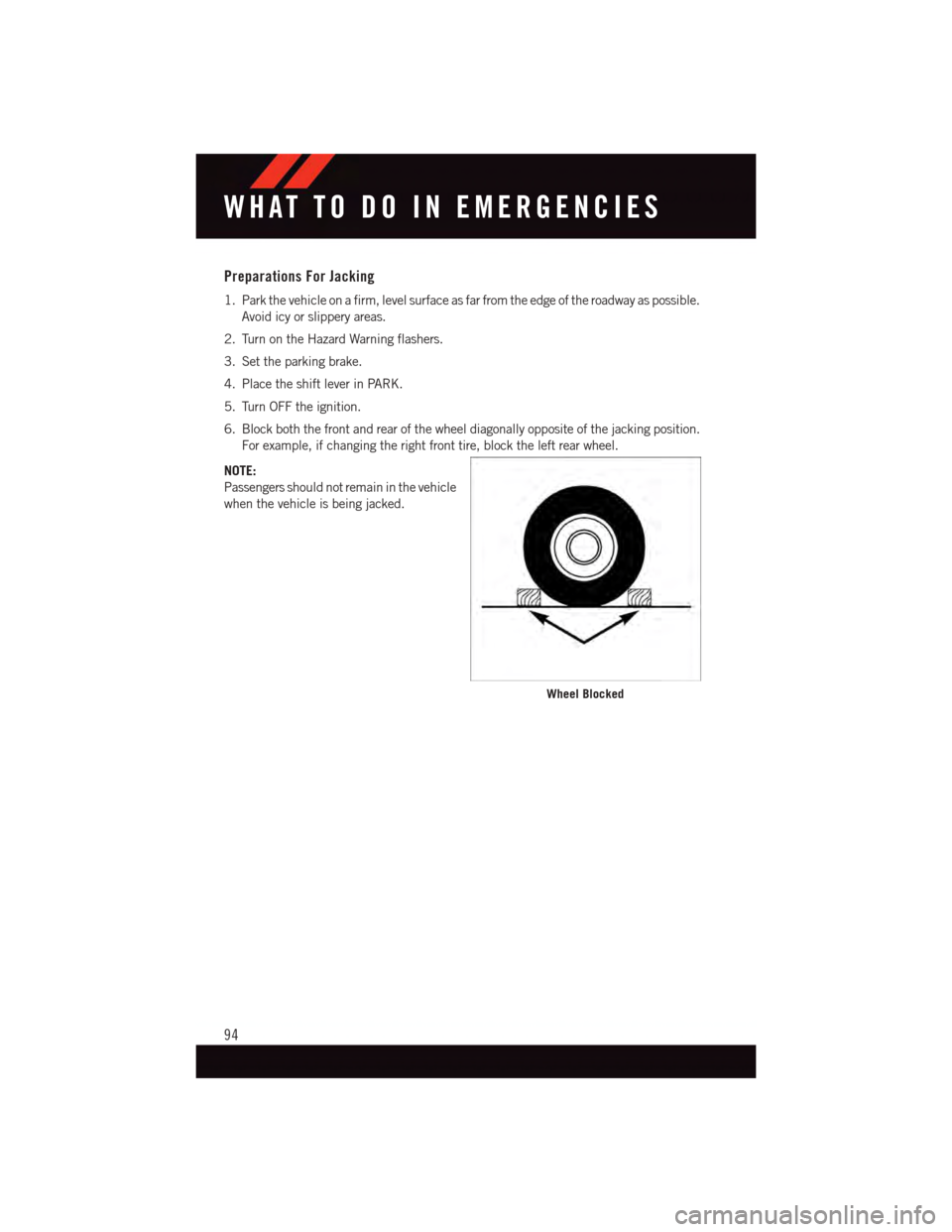
6. Block both the front and rear of the wheel diagonally opposite of the jacking position.
For example, if changing the right front tire, block the left rear wheel.
NOTE:
Passengers should not remain in the vehicle
when the vehicle is being jacked.
Wheel Blocked
WHAT TO DO IN EMERGENCIES
94
Page 97 of 140
Spare Tire Removal
NOTE:
On seven-passenger models, fold the third-row passenger seats flat. This will provide more
space when accessing the jacking tools and when operating the winch mechanism.
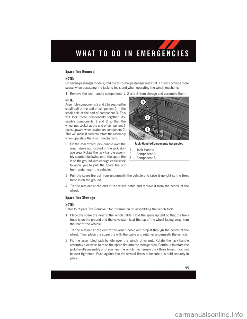
1. Remove the jack-handle components 1, 2 and 3 from storage and assemble them.
NOTE:
Assemble components 2 and 3 by seating the
small ball at the end of component 2 in the
small hole at the end of component 3. This
will lock these components together. As-
semble components 1 and 2 so that the
wheel nut socket at the end of component 1
faces upward when seated on component 2.
This will make it easier to rotate the assembly
when operating the winch mechanism.
2. Fit the assembled jack-handle over the
winch drive nut located in the jack stor-
age area. Rotate the jack-handle assem-
bly counterclockwise until the spare tire
is on the ground with enough cable slack
to allow you to pull the spare tire out
from underneath the vehicle.
3. Pull the spare tire out from underneath the vehicle and raise it upright so the tire's
tread is on the ground.
4. Tilt the retainer at the end of the winch cable and remove it from the center of the
wheel.
Spare Tire Stowage
NOTE:
Refer to “Spare Tire Removal” for information on assembling the winch tools.
1. Place the spare tire near to the winch cable. Hold the spare upright so that the tire's
tread is on the ground and the valve stem is at the top of the wheel facing away from
the rear of the vehicle.
2. Tilt the retainer at the end of the winch cable and drop it through the center of the
wheel. Then place the spare tire with the cable and retainer underneath the vehicle.
3. Fit the assembled jack-handle over the winch drive nut. Rotate the jack-handle
assembly clockwise to raise the spare tire into the storage area. Continue to rotate the
jack-handle assembly until you hear the winch mechanism click three times. It cannot
be over tightened. Push against the tire several times to be sure it is held securely in
place.
Jack-Handle/Components Assembled
1—JackHandle2—Component23—Component3
WHAT TO DO IN EMERGENCIES
95
Page 98 of 140
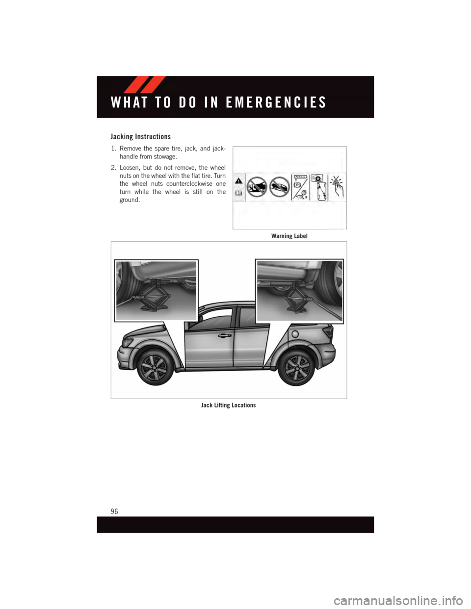
Jacking Instructions
1. Remove the spare tire, jack, and jack-
handle from stowage.
2. Loosen, but do not remove, the wheel
nuts on the wheel with the flat tire. Turn
the wheel nuts counterclockwise one
turn while the wheel is still on the
ground.
Warning Label
Jack Lifting Locations
WHAT TO DO IN EMERGENCIES
96
Page 99 of 140
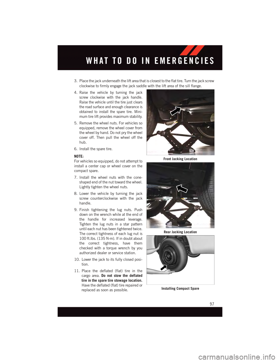
3. Place the jack underneath the lift area that is closest to the flat tire. Turn the jack screw
clockwise to firmly engage the jack saddle with the lift area of the sill flange.
4.Raise the vehicle by turning the jack
screw clockwise with the jack handle.
Raise the vehicle until the tire just clears
the road surface and enough clearance is
obtained to install the spare tire. Mini-
mum tire lift provides maximum stability.
5. Remove the wheel nuts. For vehicles so
equipped, remove the wheel cover from
the wheel by hand. Do not pry the wheel
cover off. Then pull the wheel off the
hub.
6. Install the spare tire.
NOTE:
For vehicles so equipped, do not attempt to
install a center cap or wheel cover on the
compact spare.
7. Install the wheel nuts with the cone-
shaped end of the nut toward the wheel.
Lightly tighten the wheel nuts.
8. Lower the vehicle by turning the jack
screw counterclockwise with the jack
handle.
9. Finish tightening the lug nuts. Push
down on the wrench while at the end of
the handle for increased leverage.
Ti g h t e n t h e l u g n u t s i n a s t a r p a t t e r n
until each nut has been tightened twice.
The correct tightness of each lug nut is
100 ft.lbs. (135 N·m). If in doubt about
the correct tightness, have them
checked with a torque wrench by you
authorized dealer or service station.
10. Lower the jack to its fully closed posi-
tion.
11. Place the deflated (flat) tire in the
cargo area.Do not stow the deflated
tire in the spare tire stowage location.
Have the deflated (flat) tire repaired or
replaced as soon as possible.
Front Jacking Location
Rear Jacking Location
Installing Compact Spare
WHAT TO DO IN EMERGENCIES
97