lights DODGE JOURNEY 2015 1.G User Guide
[x] Cancel search | Manufacturer: DODGE, Model Year: 2015, Model line: JOURNEY, Model: DODGE JOURNEY 2015 1.GPages: 140, PDF Size: 23.09 MB
Page 3 of 140
INTRODUCTION/WELCOME
WELCOME FROM CHRYSLERGROUP LLC..................2
CONTROLS AT A GLANCE
DRIVER COCKPIT...............4INSTRUMENT CLUSTER...........6
GETTING STARTED
KEY FOB . . . . . . . . . . . . . . . . . . . . . 8REMOTE START . . . . . . . . . . . . . . . . 9KEYLESS ENTER-N-GO™.........10VEHICLE SECURITY ALARM........14SEAT BELT SYSTEMS............15SUPPLEMENTAL RESTRAINT SYSTEM(SRS) — AIR BAGS.............16CHILD RESTRAINTS............19HEAD RESTRAINTS.............25FRONT SEATS................27REAR SEATS.................30HEATED SEATS . . . . . . . . . . . . . . . 32HEATED STEERING WHEEL........33TILT/TELESCOPING STEERINGCOLUMN...................34
OPERATING YOUR VEHICLE
ENGINE BREAK-INRECOMMENDATIONS............35TURN SIGNAL/WIPER/WASHER/HIGHBEAM LEVER.................36HEADLIGHT SWITCH............37ELECTRONIC SPEED CONTROL......38CLIMATE CONTROL.............40PA R K V I E W®REAR BACK-UP CAMERA . . 43POWER SUNROOF..............44WIND BUFFETING..............45
ELECTRONICS
YOUR VEHICLE'S SOUND SYSTEM....46IDENTIFYING YOUR RADIO.........48Uconnect®4.3 & 4.3S AT A GLANCE . . . 49Uconnect®8.4 & 8.4N AT A GLANCE . . . 51RADIO.....................53SiriusXM SATELLITE RADIO.........55iPod®/CD/AUX CONTROLS..........57GARMIN®NAVIGATION...........59SiriusXM TRAVEL LINK...........64PLAYING iPod®/USB/MP3 DEVICES....65Uconnect®PHONE..............66Uconnect®VOICE COMMAND(8.4 & 8.4N ONLY)..............72VIDEO ENTERTAINMENTSYSTEM (VES™)...............75STEERING WHEEL AUDIO CONTROLS . . 76ELECTRONIC VEHICLE INFORMATIONCENTER (EVIC)................76PROGRAMMABLE FEATURES.......77
UNIVERSAL GARAGE DOOR OPENER(HomeLink®).................78POWER INVERTER.............81POWER OUTLETS..............82
UTILITY
TRAILER TOWING WEIGHTS (MAXIMUMTRAILER WEIGHT RATINGS)........84RECREATIONAL TOWING (BEHINDMOTORHOME, ETC.)............85
WHAT TO DO IN EMERGENCIES
ROADSIDE ASSISTANCE..........86INSTRUMENT CLUSTER WARNINGLIGHTS....................86INSTRUMENT CLUSTER INDICATORLIGHTS....................91IF YOUR ENGINE OVERHEATS.......92JACKING AND TIRE CHANGING......93JUMP-STARTING..............101SHIFT LEVER OVERRIDE.........104TOWING A DISABLED VEHICLE.....105FREEING A STUCK VEHICLE.......105EVENT DATA RECORDER (EDR).....106
MAINTAINING YOUR VEHICLE
OPENING THE HOOD...........107ENGINE COMPARTMENT.........108FLUID CAPACITIES............112FLUIDS, LUBRICANTS AND GENUINEPA RT S . . . . . . . . . . . . . . . . . . . . 1 1 2MAINTENANCE PROCEDURES......114MAINTENANCE SCHEDULE........114MAINTENANCE RECORD.........118FUSES....................119TIRE PRESSURES.............121SPARE TIRES — IF EQUIPPED......122WHEEL AND WHEEL TRIM CARE....124REPLACEMENT BULBS..........124
CONSUMER ASSISTANCE
CHRYSLER GROUP LLC CUSTOMERCENTER...................126CHRYSLER CANADA INC. CUSTOMERCENTER...................126ASSISTANCE FOR THE HEARINGIMPAIRED..................126PUBLICATIONS ORDERING........126REPORTING SAFETY DEFECTS IN THEUNITED STATES..............127
MOPAR® ACCESSORIES
AUTHENTIC ACCESSORIES BYMOPAR®...................128
FREQUENTLY ASKED QUESTIONS
FREQUENTLY ASKED QUESTIONS....129
INDEX.....................130
TABLE OF CONTENTS
Page 9 of 140
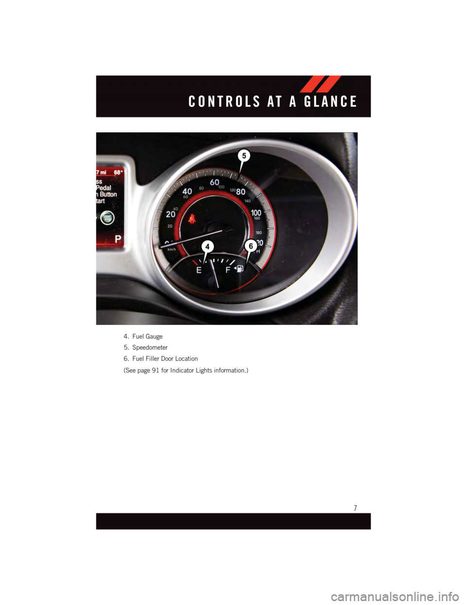
4. Fuel Gauge
5. Speedometer
6. Fuel Filler Door Location
(See page 91 for Indicator Lights information.)
CONTROLS AT A GLANCE
7
Page 10 of 140
KEY FOB
Locking And Unlocking The Doors And
Liftgate
Lock The Doors And Liftgate
•PushandreleasetheLOCKbuttonon
the RKE transmitter to lock all doors and
liftgate. The turn signal lights will flash
and the horn will chirp to acknowledge
the signal.
Unlock The Doors And Liftgate
•PushandreleasetheUNLOCKbuttonon
the RKE transmitter once to unlock the
driver’s door, or twice within five seconds
to unlock all doors and liftgate. The turn
signal lights will flash to acknowledge the
unlock signal. The illuminated entry sys-
tem will also turn on.
All doors can be programmed to unlock on
the first push of the UNLOCK button. Refer
to “Programmable Features” in the “Elec-
tronics” section of this guide.
Panic Alarm
1. Push the PANIC button once to turn the panic alarm on.
2. Wait approximately three seconds and push the button a second time to turn the panic
alarm off.
Emergency Key
Should the battery in the vehicle or the Key Fob transmitter go dead, there is an
emergency key located in the Key Fob. To remove the emergency key, slide the button at
the back of the Key Fob sideways with your thumb and then pull the key out with your
other hand.
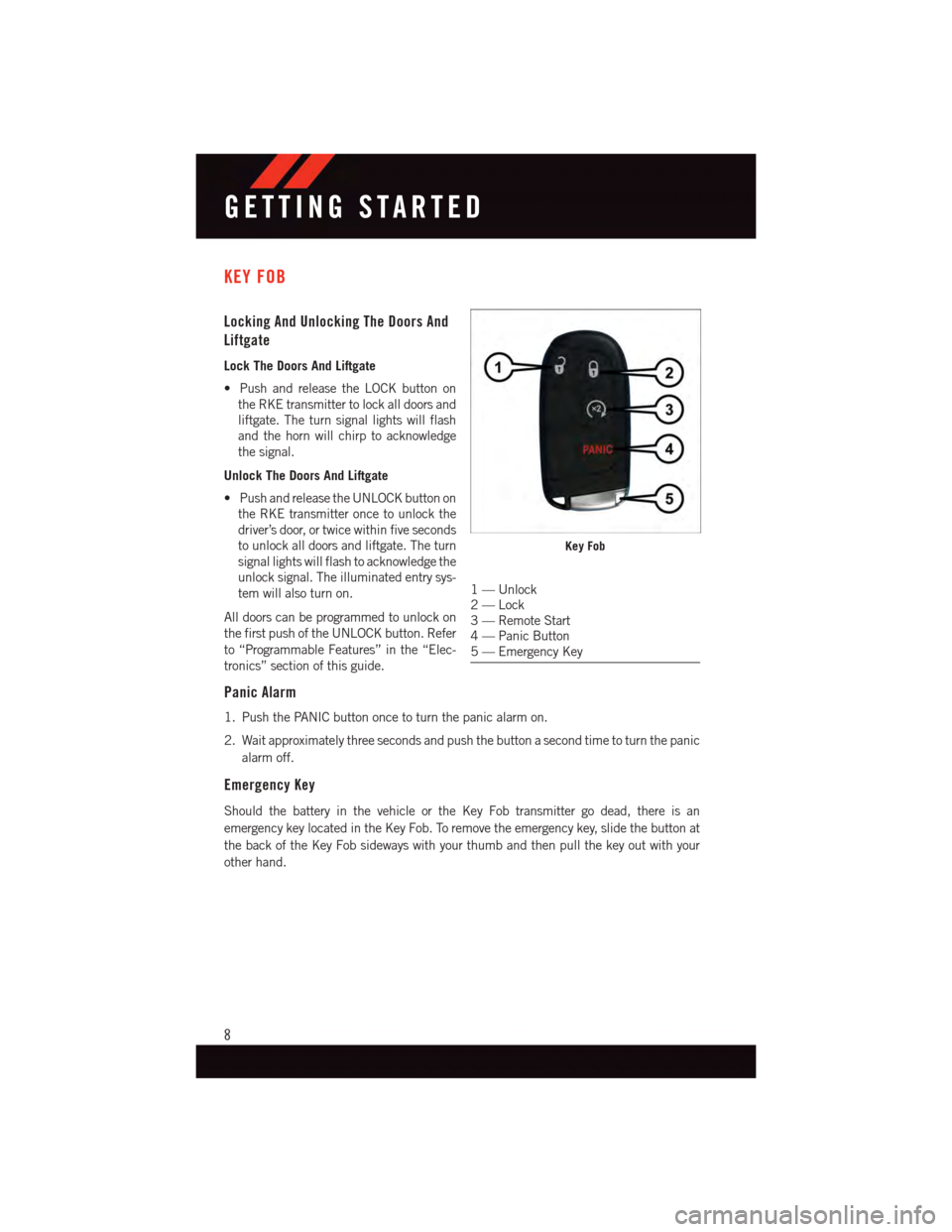
Key Fob
1—Unlock2—Lock3—RemoteStart4—PanicButton5—EmergencyKey
GETTING STARTED
8
Page 16 of 140
VEHICLE SECURITY ALARM
This Vehicle Security Alarm monitors the doors, liftgate, and ignition switch for unauthor-
ized operation.
When the alarm is activated, the interior switches for door locks are disabled. The Vehicle
Security Alarm provides both audio and visual signals repeatedly for three minutes. If the
disturbance is still present (driver's door, passenger door, other doors, ignition) after three
minutes, the parking lights and tail lights will flash for an additional 15 minutes.
To Arm:
•PushtheKeylessEnter-N-Go™START/STOPbuttonuntiltheElectronicVehicle
Information Center (EVIC) indicates that the vehicle ignition is “OFF”. Push the power
door lock switch while the door is open, push the Key Fob LOCK button, or with one of
the Key Fobs located outside the vehicle and within 5 ft (1.5 m) of the driver's and
passenger front door handles, push the Keyless Enter-N-Go™ LOCK button located on
the door handle.
NOTE:
After pushing the Keyless Enter-N-Go™ LOCK button, you must wait two seconds before
you can lock or unlock the vehicle via the door handle.
To Disarm:
•PushtheKeyFobUNLOCKbuttonorwithoneoftheKeyFobslocatedoutsidethe
vehicle and within 5 ft (1.5 m) of the driver's and passenger front door handles, grab the
Keyless Enter-N-Go™ door handle and enter the vehicle, then push the Keyless
Enter-N-Go™ START/STOP button (requires at least one valid Key Fob in the vehicle).
GETTING STARTED
14
Page 39 of 140
HEADLIGHT SWITCH
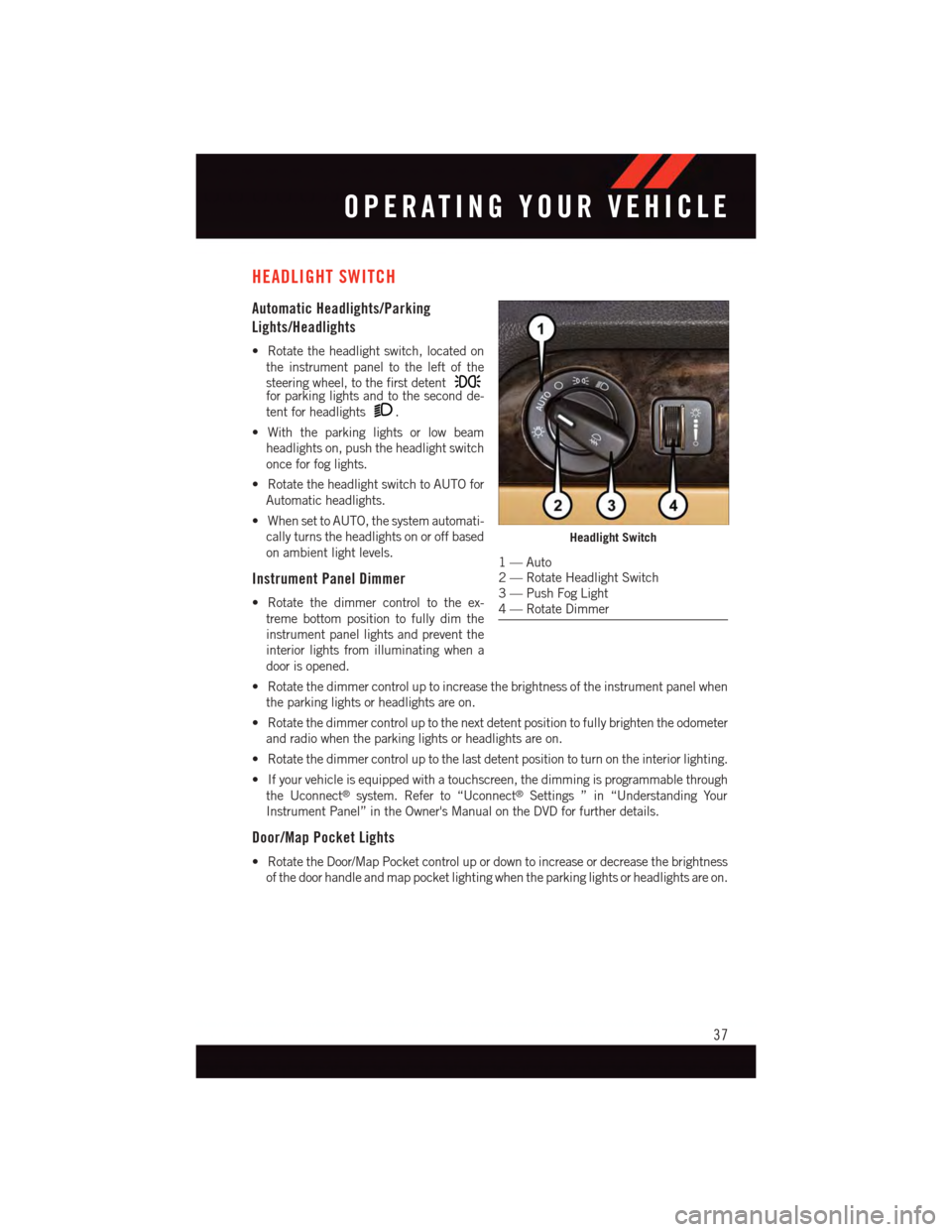
Automatic Headlights/Parking
Lights/Headlights
•Rotatetheheadlightswitch,locatedon
the instrument panel to the left of the
steering wheel, to the first detentfor parking lights and to the second de-
tent for headlights.
•Withtheparkinglightsorlowbeam
headlights on, push the headlight switch
once for fog lights.
•RotatetheheadlightswitchtoAUTOfor
Automatic headlights.
•WhensettoAUTO,thesystemautomati-
cally turns the headlights on or off based
on ambient light levels.
Instrument Panel Dimmer
•Rotatethedimmercontroltotheex-
treme bottom position to fully dim the
instrument panel lights and prevent the
interior lights from illuminating when a
door is opened.
•Rotatethedimmercontroluptoincreasethebrightnessoftheinstrumentpanelwhen
the parking lights or headlights are on.
•Rotatethedimmercontroluptothenextdetentpositiontofullybrightentheodometer
and radio when the parking lights or headlights are on.
•Rotatethedimmercontroluptothelastdetentpositiontoturnontheinteriorlighting.
•Ifyourvehicleisequippedwithatouchscreen,thedimmingisprogrammablethrough
the Uconnect®system. Refer to “Uconnect®Settings ” in “Understanding Your
Instrument Panel” in the Owner's Manual on the DVD for further details.
Door/Map Pocket Lights
•RotatetheDoor/MapPocketcontrolupordowntoincreaseordecreasethebrightness
of the door handle and map pocket lighting when the parking lights or headlights are on.
Headlight Switch
1—Auto2—RotateHeadlightSwitch3—PushFogLight4—RotateDimmer
OPERATING YOUR VEHICLE
37
Page 79 of 140
Compass Calibration
This compass is self-calibrating, which eliminates the need to set the compass manually.
When the vehicle is new, the compass may appear erratic and the EVIC will display “CAL”
until the compass is calibrated.
Yo u m a y a l s o c a l i b r a t e t h e c o m p a s s b y c o m p l e t i n g o n e o r m o r e 3 6 0 d e g r e e t u r n s ( i n a n
area free from large metal or metallic objects) until the “CAL” message displayed in the
EVIC turns off. The compass will now function normally.
PROGRAMMABLE FEATURES
Electronic Vehicle Information Center (EVIC) — If Equipped
•TheEVICcanbeusedtovieworchangethefollowingsettings.PushtheUPor
DOWNbutton until System Setup displays, then push the SELECTbutton.
Scroll through the settings using the UP or DOWN buttons. Push the SELECT
button to change the setting. Push the BACK button to scroll back to a previous menu
or sub menu.
•Fuel Economy•Average Fuel Economy•DistanceToEmpty(DTE)•MilesPerGallon(MPG)
•Tr i p I n f o•Tr i p A•TripB•ElapsedTime
•Vehicle Speed•Ti r e P S I
•Messages•VehicleInfo(CustomerInformation
Features)
Uconnect® 4.3 Customer Programmable Features
•TheUconnect®4.3 system allows you to access Customer Programmable feature
settings such as Display, Clock, Safety/Assistance, Lights, Doors & Locks, Heated
Seats, Engine Off Operation, Compass Settings, Audio, Phone/ Bluetooth®and SIRIUS
Setup through buttons on the faceplate and buttons on the touchscreen.
•Pressthe“Settings”buttonontherightsideoftheunittoaccesstheSettingsscreen,
use the “Page Up/Down” buttons on the touchscreen to scroll through the following
settings. The following feature settings are available:
•Display•AutoOnComfort&RemoteStart
•Clock•EngineOffOptions
•Safety/Assistance•Audio
•Lights•Phone/Bluetooth®
•Doors&Locks•SIRIUSSetup
ELECTRONICS
77
Page 80 of 140
Uconnect® 8.4 Customer Programmable Features
•TheUconnect®8.4 system allows you to access Customer Programmable feature
settings such as Display, Clock, Safety/Assistance, Lights, Doors & Locks, Heated
Seats, Engine Off Operation, Compass Settings, Audio, Phone/Bluetooth®and SIRIUS
Setup through buttons on the touchscreen.
•Pressthe“More”buttononthebottomofthetouchscreen,thenpressthe“Settings”
button on the faceplate to access the Settings screen. When making a selection, scroll
up or down until the preferred setting is highlighted, then press and release the
preferred setting until a check-mark appears next to the setting, showing that setting
has been selected. The following feature settings are available:
•Display•AutoOnComfort&RemoteStart
•Clock•EngineOffOptions
•Safety/Assistance•Audio
•Lights•Phone/Bluetooth®
•Doors&Locks•SIRIUSSetup
UNIVERSAL GARAGE DOOR OPENER (HomeLink®)
•HomeLink®replaces up to three hand-held transmitters that operate devices such as
garage door openers, motorized gates, lighting or home security systems. The
HomeLink®unit is powered by your vehicles 12 Volt battery.
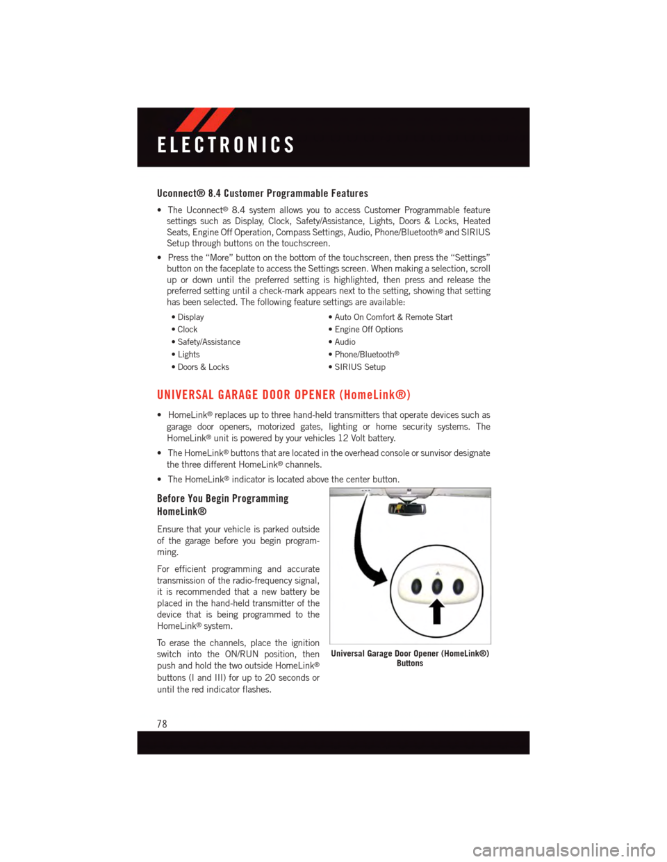
•TheHomeLink®buttons that are located in the overhead console or sunvisor designate
the three different HomeLink®channels.
•TheHomeLink®indicator is located above the center button.
Before You Begin Programming
HomeLink®
Ensure that your vehicle is parked outside
of the garage before you begin program-
ming.
For efficient programming and accurate
transmission of the radio-frequency signal,
it is recommended that a new battery be
placed in the hand-held transmitter of the
device that is being programmed to the
HomeLink®system.
To e r a s e t h e c h a n n e l s , p l a c e t h e i g n i t i o n
switch into the ON/RUN position, then
push and hold the two outside HomeLink®
buttons (I and III) for up to 20 seconds or
until the red indicator flashes.
Universal Garage Door Opener (HomeLink®)Buttons
ELECTRONICS
78
Page 88 of 140
ROADSIDE ASSISTANCE
Dial toll-free 1-800-521-2779 for U.S. Residents or 1-800-363-4869 for Canadian
Residents.
•Provideyourname,vehicleidentificationnumber,licenseplatenumber,andyour
location, including the telephone number from which you are calling.
•Brieflydescribethenatureoftheproblemandanswerafewsimplequestions.
•Youwillbegiventhenameoftheserviceproviderandanestimatedtimeofarrival.If
you feel you are in an “unsafe situation”, please let us know. With your consent, we will
contact local police or safety authorities.
INSTRUMENT CLUSTER WARNING LIGHTS
-LowFuelWarningLight
This warning light indicates when the fuel level reaches approximately 2.0 gal (7.8 L), this
light will turn on and a single chime will sound.
-ChargingSystemLight
This light shows the status of the electrical charging system. If the charging system light
remains on, it means that the vehicle is experiencing a problem with the charging system.
We recommend you do not continue driving if the charging system light is on. Have the
vehicle serviced immediately.
-OilPressureWarningLight
This light indicates low engine oil pressure. If the light turns on while driving, stop the
vehicle and shut off the engine as soon as possible. A chime will sound for four minutes
when this light turns on.
We recommend you do not operate the vehicle or engine damage will occur. Have the
vehicle serviced immediately.
-Anti-LockBrake(ABS)Light
This light monitors the Anti-Lock Brake System (ABS). The light will turn on when the
ignition switch is turned to the ON/RUN position and may stay on for as long as four
seconds.
If the ABS light remains on or turns on while driving, it indicates that the Anti-Lock portion
of the brake system is not functioning and that service is required. However, the
conventional brake system will continue to operate normally if the BRAKE warning light is
not on.
If the ABS light is on, the brake system should be serviced as soon as possible to restore
the benefits of Anti-Lock brakes. If the ABS light does not turn on when the ignition switch
is turned to the ON/RUN position, have the light inspected by an authorized dealer.
WHAT TO DO IN EMERGENCIES
86
Page 93 of 140
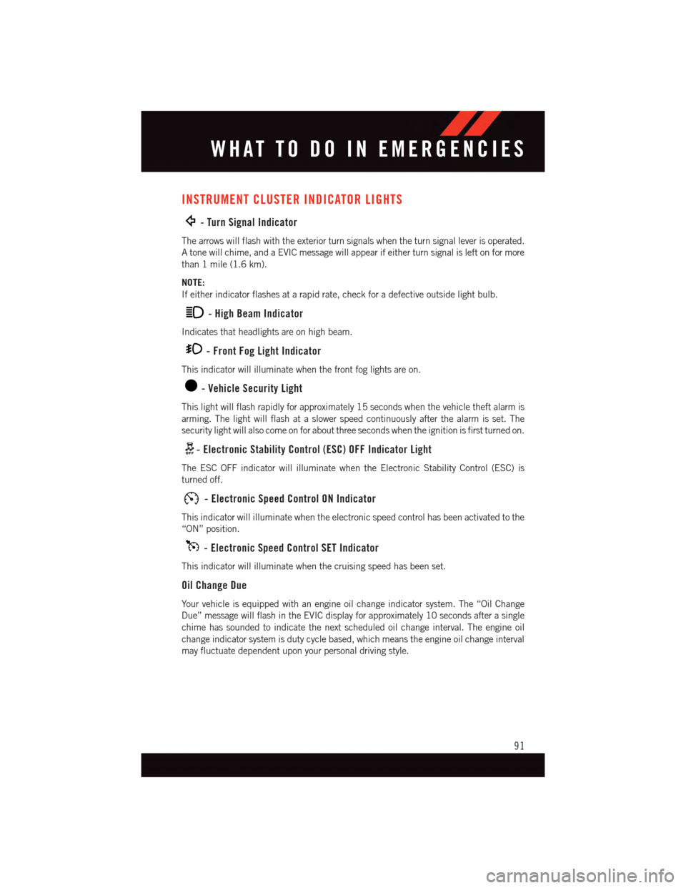
INSTRUMENT CLUSTER INDICATOR LIGHTS
-TurnSignalIndicator
The arrows will flash with the exterior turn signals when the turn signal lever is operated.
Atonewillchime,andaEVICmessagewillappearifeitherturnsignalisleftonformore
than 1 mile (1.6 km).
NOTE:
If either indicator flashes at a rapid rate, check for a defective outside light bulb.
-HighBeamIndicator
Indicates that headlights are on high beam.
-FrontFogLightIndicator
This indicator will illuminate when the front fog lights are on.
-VehicleSecurityLight
This light will flash rapidly for approximately 15 seconds when the vehicle theft alarm is
arming. The light will flash at a slower speed continuously after the alarm is set. The
security light will also come on for about three seconds when the ignition is first turned on.
-ElectronicStabilityControl(ESC)OFFIndicatorLight
The ESC OFF indicator will illuminate when the Electronic Stability Control (ESC) is
turned off.
-ElectronicSpeedControlONIndicator
This indicator will illuminate when the electronic speed control has been activated to the
“ON” position.
-ElectronicSpeedControlSETIndicator
This indicator will illuminate when the cruising speed has been set.
Oil Change Due
Yo u r v e h i c l e i s e q u i p p e d w i t h a n e n g i n e o i l c h a n g e i n d i c a t o r s y s t e m . T h e “ O i l C h a n g e
Due” message will flash in the EVIC display for approximately 10 seconds after a single
chime has sounded to indicate the next scheduled oil change interval. The engine oil
change indicator system is duty cycle based, which means the engine oil change interval
may fluctuate dependent upon your personal driving style.
WHAT TO DO IN EMERGENCIES
91
Page 117 of 140
Yo u r a u t h o r i z e d d e a l e r w i l l r e s e t t h e o i l c h a n g e i n d i c a t o r m e s s a g e a f t e r c o m p l e t i n g t h e
scheduled oil change. If a scheduled oil change is performed by someone other than your
authorized dealer, the message can be reset by referring to the steps described under
“Instrument Cluster Warning Lights” in “What To Do In Emergencies” in this guide or
“Electronic Vehicle Information Center (EVIC)” in “Understanding Your Instrument
Panel” in your Owners Manual on the DVD for further information.
NOTE:
Under no circumstances should oil change intervals exceed 10,000 miles (16,000 km)
or twelve months, whichever comes first.
Severe Duty All Models
Change Engine Oil at 4000 miles (6,500 km) if the vehicle is operated in a dusty and off
road environment. This type of vehicle use is considered Severe Duty.
Once A Month Or Before A Long Trip:
•Checkengineoillevel.
•Checkwindshieldwasherfluidlevel.
•Checktirepressureandlookforunusualwearordamage.Rotatetiresatthefirstsign
of irregular wear, even if it occurs before the oil indicator system turns on.
•Checkthefluidlevelsofthecoolantreservoir,brakemastercylinder,powersteering
and transmission (4-speed only) and fill as needed.
•Checkfunctionofallinteriorandexteriorlights.
Required Maintenance Intervals.
Refer to the Maintenance Schedules on the following page for the required maintenance
intervals.
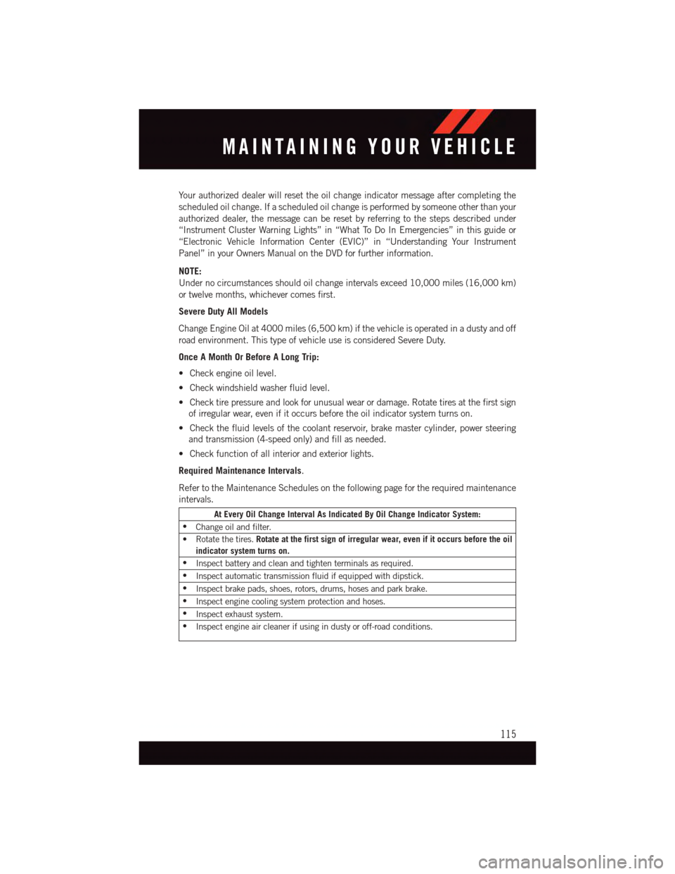
At Every Oil Change Interval As Indicated By Oil Change Indicator System:
•Change oil and filter.
•Rotatethetires.Rotate at the first sign of irregular wear, even if it occurs before the oil
indicator system turns on.
•Inspect battery and clean and tighten terminals as required.
•Inspect automatic transmission fluid if equipped with dipstick.
•Inspect brake pads, shoes, rotors, drums, hoses and park brake.
•Inspect engine cooling system protection and hoses.
•Inspect exhaust system.
•Inspect engine air cleaner if using in dusty or off-road conditions.
MAINTAINING YOUR VEHICLE
115