Gas DODGE JOURNEY 2020 User Guide
[x] Cancel search | Manufacturer: DODGE, Model Year: 2020, Model line: JOURNEY, Model: DODGE JOURNEY 2020Pages: 396, PDF Size: 25.53 MB
Page 178 of 396
176 STARTING AND OPERATING
The following table shows the approximate
distances for each zone:
NOTE:
If snow, ice, mud, or any foreign substance
bu
ilds up on the camera lens, clean the lens,
rinse with water, and dry with a soft cloth. Do
not cover the lens.
REFUELING THE VEHICLE
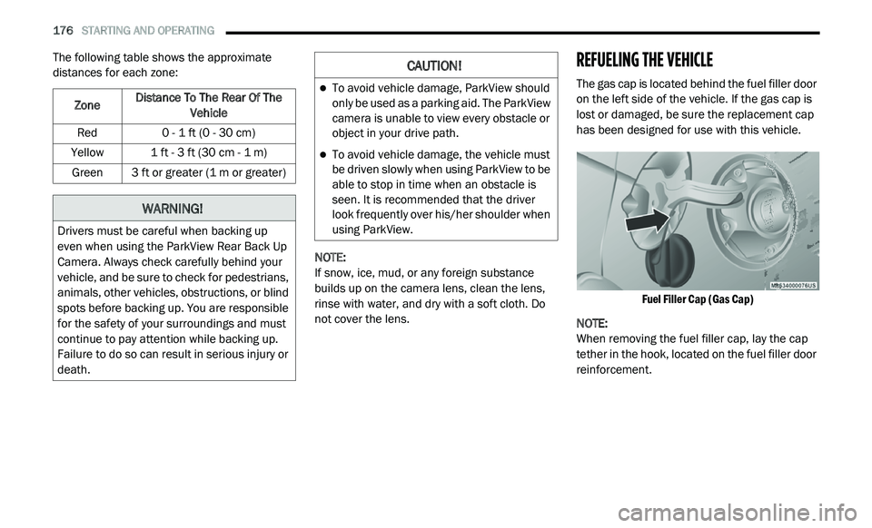
The gas cap is located behind the fuel filler door
on the left side of the vehicle. If the gas cap is
lost or damaged, be sure the replacement cap
has been designed for use with this vehicle.
Fuel Filler Cap (Gas Cap)
NOTE:
When removing the fuel filler cap, lay the cap
t e
ther in the hook, located on the fuel filler door
reinforcement.
Zone
Distance To The Rear Of The
Ve
hicle
Red 0 - 1 ft (0 - 30 cm)
Yellow 1 ft - 3 ft (30 cm - 1 m)
Green 3 ft or greater (1 m or greater)
WARNING!
Drivers must be careful when backing up
even when using the ParkView Rear Back Up
Camera. Always check carefully behind your
vehicle, and be sure to check for pedestrians,
animals, other vehicles, obstructions, or blind
spots before backing up. You are responsible
for the safety of your surroundings and must
continue to pay attention while backing up.
Failure to do so can result in serious injury or
death.
CAUTION!
To avoid vehicle damage, ParkView should
only be used as a parking aid. The ParkView
camera is unable to view every obstacle or
object in your drive path.
To avoid vehicle damage, the vehicle must
be driven slowly when using ParkView to be
able to stop in time when an obstacle is
seen. It is recommended that the driver
look frequently over his/her shoulder when
using ParkView.
Page 179 of 396
STARTING AND OPERATING 177
(Continued)
NOTE:
Tighten the gas cap until you hear a “clicking”
s o
und. This is an indication that the gas cap is
tightened properly. The MIL in the instrument
cluster may turn on if the gas cap is not secured
properly. Make sure that the gas cap is tight -
ened each time the vehicle is refueled.
LOOSE FUEL FILLER CAP MESSAGE
If the vehicle diagnostic system determines that
the fuel filler cap is loose, improperly installed,
or damaged, a ”gASCAP” message will display in
the odometer or a “Check Gascap” message will
display in the instrument cluster. If this occurs,
tighten the fuel filler cap properly and press the
Trip Odometer button to turn off the message. If
the problem continues, the message will appear
the next time the vehicle is started.
A loose, improperly installed, or damaged fuel
f i
ller cap may also turn on the MIL.
VEHICLE LOADING
The load carrying capacity of your vehicle is
shown on the “Vehicle Certification Label”. This
information should be used for passenger and
luggage loading as indicated.
Do not exceed the specified Gross Vehicle
W e
ight Rating (GVWR) or the Gross Axle Weight
Rating (GAWR).
VEHICLE CERTIFICATION LABEL
Your vehicle has a Vehicle Certification Label
affixed to the drivers side B-pillar or the rear of
the driver’s door.
The label contains the following information:
Name of manufacturer
Month and year of manufacture
Gross Vehicle Weight Rating (GVWR)
Gross Axle Weight Rating (GAWR) front
Gross Axle Weight Rating (GAWR) rear
Vehicle Identification Number (VIN)
Type of vehicle
Month, Day, and Hour of manufacture (MDH)
WARNING!
Never have any smoking materials lit in or
near the vehicle when the gas cap is
removed or the tank is being filled.
Never add fuel to the vehicle when the
engine is running.
A fire may result if gasoline is pumped into
a portable container that is inside of a
vehicle. You could be burned. Always place
gas containers on the ground while filling.
Failure to follow this warning may result in
serious injury or death.
CAUTION!
Damage to the fuel system or emissions
control system could result from using an
improper fuel tank filler tube cap.
A poorly fitting fuel filler cap could let impu -
rities into the fuel system.
A poorly fitting fuel filler cap may cause the
“Malfunction Indicator Light (MIL)” to turn on.
To avoid fuel spillage and overfilling, do not
“top off” the fuel tank after filling. When the
fuel nozzle “clicks” or shuts off, the fuel
tank is full.
CAUTION! (Continued)
5
Page 209 of 396
IN CASE OF EMERGENCY 207
(Continued)
PREPARATIONS FOR JUMP START
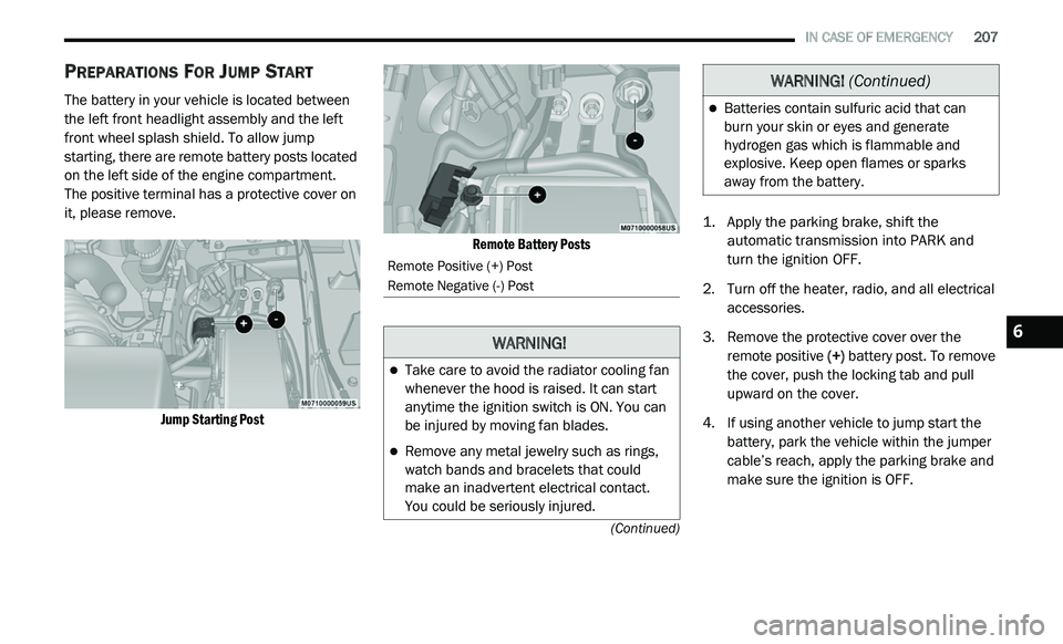
The battery in your vehicle is located between
the left front headlight assembly and the left
front wheel splash shield. To allow jump
starting, there are remote battery posts located
on the left side of the engine compartment.
The positive terminal has a protective cover on
i t
, please remove.
Jump Starting Post Remote Battery Posts
1. Ap
ply the parking brake, shift the
a
utomatic transmission into PARK and
turn the ignition OFF.
2. T urn off the heater, radio, and all electrical
a
ccessories.
3. R emove the protective cover over the
r
emote positive (+) battery post. To remove
the cover, push the locking tab and pull
upward on the cover.
4. If using another vehicle to jump start the b
attery, park the vehicle within the jumper
cable’s reach, apply the parking brake and
make sure the ignition is OFF.
Remote Positive (+) Post
Remote Negative (-) Post
WARNING!
Take care to avoid the radiator cooling fan
whenever the hood is raised. It can start
anytime the ignition switch is ON. You can
be injured by moving fan blades.
Remove any metal jewelry such as rings,
watch bands and bracelets that could
make an inadvertent electrical contact.
You could be seriously injured.
Batteries contain sulfuric acid that can
burn your skin or eyes and generate
hydrogen gas which is flammable and
explosive. Keep open flames or sparks
away from the battery.
WARNING! (Continued)
6
Page 224 of 396
222 SERVICING AND MAINTENANCE
To access the battery, turn the steering wheel
fully to the right and remove the access panel
from the inner fender shield.
PRESSURE WASHING
DEALER SERVICE
An authorized dealer has qualified service
personnel, special tools, and equipment to
perform all service operations in an expert
manner. Service Manuals are available which
include detailed service information for your
vehicle. Refer to these Service Manuals before
attempting any procedure yourself.
NOTE:
Intentional tampering with emissions control
s y
stems may void your warranty and could result
in civil penalties being assessed against you.
WARNING!
Battery fluid is a corrosive acid solution and
can burn or even blind you. Do not allow
battery fluid to contact your eyes, skin, or
clothing. Do not lean over a battery when
attaching clamps. If acid splashes in eyes
or on skin, flush the area immediately with
large amounts of water.
Battery gas is flammable and explosive.
Keep flame or sparks away from the
battery. Do not use a booster battery or any
other booster source with an output greater
than 12 Volts. Do not allow cable clamps to
touch each other.
Battery posts, terminals, and related acces -
sories contain lead and lead compounds.
W a
sh hands after handling.
CAUTION!
It is essential when replacing the cables on
the battery that the positive cable is
attached to the positive post and the nega -
tive cable is attached to the negative post.
B a
ttery posts are marked positive (+) and
negative (-) and are identified on the battery
case. Cable clamps should be tight on the
terminal posts and free of corrosion.
If a “fast charger” is used while the battery
is in the vehicle, disconnect both vehicle
battery cables before connecting the
charger to the battery. Do not use a “fast
charger” to provide starting voltage.
CAUTION!
Cleaning the engine compartment with a high
pressure washer is not recommended.
Precautions have been taken to safeguard
all parts and connections however, the
p r
essures generated by these machines is
such that complete protection against water
ingress cannot be guaranteed.
WARNING!
You can be badly injured working on or
around a motor vehicle. Only do service work
for which you have the knowledge and the
proper equipment. If you have any doubt
about your ability to perform a service job,
take your vehicle to a competent mechanic.
Page 228 of 396
226 SERVICING AND MAINTENANCE
Some conditions can be caused by a faulty
component such as a belt pulley. Belt pulleys
should be carefully inspected for damage and
proper alignment.
Belt replacement on some models requires the
us
e of special tools, we recommend having your
vehicle serviced at an authorized dealer.
BODY LUBRICATION
Locks and all body pivot points, including such
items as seat tracks, door hinge pivot points
and rollers, liftgate, tailgate, decklid, sliding
doors and hood hinges, should be lubricated
periodically with a lithium based grease, such
as Mopar Spray White Lube to ensure quiet,
easy operation and to protect against rust and
wear. Prior to the application of any lubricant,
the parts concerned should be wiped clean to
remove dust and grit; after lubricating, excess
oil and grease should be removed. Particular
attention should also be given to hood latching
components to ensure proper function. When
performing other underhood services, the hood
latch, release mechanism and safety catch
should be cleaned and lubricated.
The external lock cylinders should be lubricated
t w
ice a year, preferably in the Autumn and Spring. Apply a small amount of a high quality
lubricant, such as Mopar Lock Cylinder
Lubricant directly into the lock cylinder.
WINDSHIELD WIPER BLADES
Clean the rubber edges of the wiper blades and
the windshield periodically with a sponge or soft
cloth and a mild nonabrasive cleaner. This will
remove accumulations of salt or road film.
Operation of the wipers on dry glass for long
p
e
riods may cause deterioration of the wiper
blades. Always use washer fluid when using
the wipers to remove salt or dirt from a dry
w i
ndshield.
Avoid using the wiper blades to remove frost or
i c
e from the windshield. Keep the blade rubber
out of contact with petroleum products such as
engine oil, gasoline, etc.
NOTE:
Life expectancy of wiper blades varies
d e
pending on geographical area and frequency
of use. Poor performance of blades may be
present with chattering, marks, water lines or
wet spots. If any of these conditions are
present, clean the wiper blades or replace as
necessary.
Rear Wiper Blade Removal/Installation
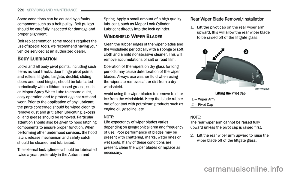
1. Lift the pivot cap on the rear wiper arm upward, this will allow the rear wiper blade
to be raised off of the liftgate glass.
Lifting The Pivot Cap
NOTE:
The rear wiper arm cannot be raised fully
u p
ward unless the pivot cap is raised first.
2. Li ft the rear wiper arm upward to raise the
w
iper blade off of the liftgate glass.
1 — Wiper Arm
2 — Pivot Cap
Page 229 of 396
SERVICING AND MAINTENANCE 227
(Continued)
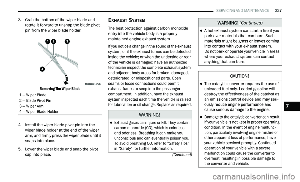
3. Grab the bottom of the wiper blade and rotate it forward to unsnap the blade pivot
pin from the wiper blade holder.
Removing The Wiper Blade
4. I nstall the wiper blade pivot pin into the
w
iper blade holder at the end of the wiper
arm, and firmly press the wiper blade until it
snaps into place.
5. Lower the wiper blade and snap the pivot c
ap into place.
EXHAUST SYSTEM
The best protection against carbon monoxide
entry into the vehicle body is a properly
maintained engine exhaust system.
If you notice a change in the sound of the exhaust
sy
stem; or if the exhaust fumes can be detected
inside the vehicle; or when the underside or rear
of the vehicle is damaged; have an authorized
technician inspect the complete exhaust system
and adjacent body areas for broken, damaged,
deteriorated, or mispositioned parts. Open
seams or loose connections could permit
exhaust fumes to seep into the passenger
compartment. In addition, have the exhaust
system inspected each time the vehicle is raised
for lubrication or oil change. Replace as required.
1 — Wiper Blade
2 — Blade Pivot Pin
3 — Wiper Arm
4 — Wiper Blade Holder
WARNING!
Exhaust gases can injure or kill. They contain
carbon monoxide (CO), which is colorless
and odorless. Breathing it can make you
unconscious and can eventually poison you.
To avoid breathing CO, refer to “Safety Tips”
in “Safety” for further information.
A hot exhaust system can start a fire if you
park over materials that can burn. Such
materials might be grass or leaves coming
into contact with your exhaust system.
Do not park or operate your vehicle in areas
w h
ere your exhaust system can contact
anything that can burn.
CAUTION!
The catalytic converter requires the use of
unleaded fuel only. Leaded gasoline will
destroy the effectiveness of the catalyst as
an emissions control device and may seri -
ously reduce engine performance and
c a
use serious damage to the engine.
Damage to the catalytic converter can result
if your vehicle is not kept in proper operating
condition. In the event of engine malfunc -
tion, particularly involving engine misfire or
o t
her apparent loss of performance, have
your vehicle serviced promptly. Continued
operation of your vehicle with a severe
malfunction could cause the converter to
overheat, resulting in possible damage to
the converter and vehicle.
WARNING! (Continued)
7
Page 233 of 396

SERVICING AND MAINTENANCE 231
Coolant Level
The coolant bottle provides a quick visual
method for determining that the coolant level is
adequate. With the engine idling and warm to
normal operating temperature, the level of the
coolant in the bottle should be between the
“ADD” and “FULL” lines, shown on the bottle.
The radiator normally remains completely full,
so
there is no need to remove the radiator cap
unless checking for coolant freeze point or
replacing engine coolant (antifreeze). Advise
your service attendant of this. As long as the
engine operating temperature is satisfactory,
the coolant bottle need only be checked once a
month. When additional engine coolant
(antifreeze) is needed to maintain the proper
level, it should be added to the coolant bottle.
Do not overfill. See “Adding Coolant” in
“Servicing and Maintenance” for further
information.
Points To Remember
NOTE:
When the vehicle is stopped after a few miles/
k i
lometers of operation, you may observe vapor
coming from the front of the engine compart -
ment. This is normally a result of moisture from
r a
in, snow, or high humidity accumulating on
the radiator and being vaporized when the ther -
mostat opens, allowing hot engine coolant (anti -
freeze) to enter the radiator.
If an examination of your engine compartment
s h
ows no evidence of radiator or hose leaks,
the vehicle may be safely driven. The vapor will
soon dissipate.
Do not overfill the coolant expansion bottle.
Check the coolant freeze point in the radiator
and in the coolant expansion bottle. If engine
coolant (antifreeze) needs to be added, the
contents of the coolant expansion bottle
must also be protected against freezing.
If frequent engine coolant (antifreeze) addi-
tions are required, the cooling system should
b e
pressure tested for leaks.
Maintain engine coolant (antifreeze) concen -
tration at a minimum of 50% OAT coolant
( c
onforming to MS.90032) and distilled water
for proper corrosion protection of your engine
which contains aluminum components.
Make sure that the coolant expansion bottle
overflow hoses are not kinked or obstructed.
Keep the front of the radiator clean. If your
vehicle is equipped with air conditioning,
keep the front of the condenser clean.
Do not change the thermostat for Summer or
Winter operation. If replacement is ever
necessary, install ONLY the correct type ther -
mostat. Other designs may result in unsatis -
factory engine coolant (antifreeze)
p e
rformance, poor gas mileage, and
increased emissions.
7
Page 247 of 396
SERVICING AND MAINTENANCE 245
Tread Wear Indicators
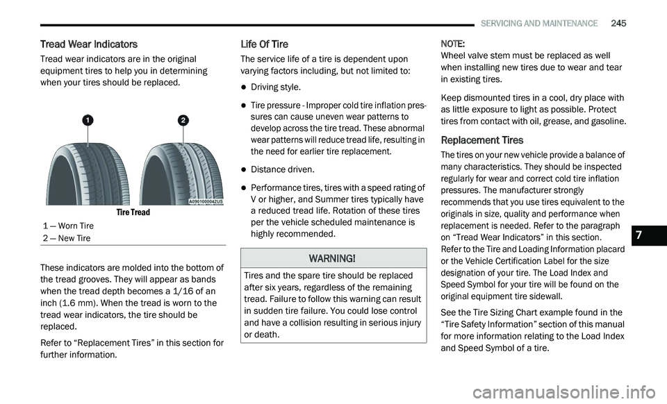
Tread wear indicators are in the original
equipment tires to help you in determining
when your tires should be replaced.
Tire Tread
These indicators are molded into the bottom of
th
e tread grooves. They will appear as bands
when the tread depth becomes a 1/16 of an
inch (1.6 mm). When the tread is worn to the
t r
ead wear indicators, the tire should be
replaced.
Refer to “Replacement Tires” in this section for
f u
rther information.
Life Of Tire
The service life of a tire is dependent upon
varying factors including, but not limited to:
Driving style.
Tire pressure - Improper cold tire inflation pres -
sures can cause uneven wear patterns to
d e
velop across the tire tread. These abnormal
wear patterns will reduce tread life, resulting in
the need for earlier tire replacement.
Distance driven.
Performance tires, tires with a speed rating of
V or higher, and Summer tires typically have
a reduced tread life. Rotation of these tires
per the vehicle scheduled maintenance is
highly recommended. NOTE:
Wheel valve stem must be replaced as well
w h
en installing new tires due to wear and tear
in existing tires.
Keep dismounted tires in a cool, dry place with
a s
little exposure to light as possible. Protect
tires from contact with oil, grease, and gasoline.
Replacement Tires
The tires on your new vehicle provide a balance of
many characteristics. They should be inspected
regularly for wear and correct cold tire inflation
pressures. The manufacturer strongly
recommends that you use tires equivalent to the
originals in size, quality and performance when
replacement is needed. Refer to the paragraph
on “Tread Wear Indicators” in this section.
Refer to the Tire and Loading Information placard
o r
the Vehicle Certification Label for the size
designation of your tire. The Load Index and
Speed Symbol for your tire will be found on the
original equipment tire sidewall.
See the Tire Sizing Chart example found in the
“T
ire Safety Information” section of this manual
for more information relating to the Load Index
and Speed Symbol of a tire.
1 — Worn Tire
2 — New Tire
WARNING!
Tires and the spare tire should be replaced
after six years, regardless of the remaining
tread. Failure to follow this warning can result
in sudden tire failure. You could lose control
and have a collision resulting in serious injury
or death.
7
Page 259 of 396
TECHNICAL SPECIFICATIONS 257
WHEEL AND TIRE TORQUE SPECIFICATIONS
Proper lug nut/bolt torque is very important to
ensure that the wheel is properly mounted to
the vehicle. Any time a wheel has been removed
and reinstalled on the vehicle, the lug nuts/
bolts should be torqued using a properly
calibrated torque wrench using a high quality six
sided (hex) deep wall socket.
TORQUE SPECIFICATIONS
**Use only authorized dealer recommended
lug nuts/bolts and clean or remove any dirt or
oil before tightening.
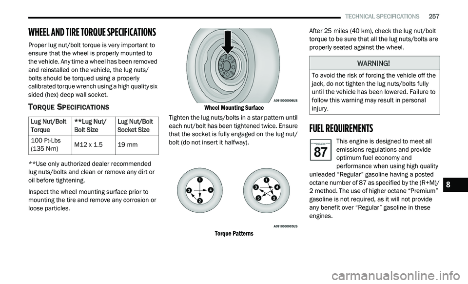
Inspect the wheel mounting surface prior to
mo
unting the tire and remove any corrosion or
loose particles.
Wheel Mounting Surface
Tighten the lug nuts/bolts in a star pattern until
ea
ch nut/bolt has been tightened twice. Ensure
that the socket is fully engaged on the lug nut/
bolt (do not insert it halfway).
Torque Patterns
After 25
miles (40 km), check the lug nut/bolt
t o
rque to be sure that all the lug nuts/bolts are
properly seated against the wheel.
FUEL REQUIREMENTS
This engine is designed to meet all
emissions regulations and provide
o p
timum fuel economy and
performance when using high quality
unleaded “Regular” gasoline having a posted
octane number of 87 as specified by the (R+M)/
2 method. The use of higher octane “Premium”
g a
soline is not required, as it will not provide
any benefit over “Regular” gasoline in these
engines.
Lug Nut/Bolt
T
o
rque **Lug Nut/
Bo
lt Size Lug Nut/Bolt
So
cket Size
100 Ft-Lbs
( 1
35 N·m) M12 x 1.5
19 mm
WARNING!
To avoid the risk of forcing the vehicle off the
jack, do not tighten the lug nuts/bolts fully
until the vehicle has been lowered. Failure to
follow this warning may result in personal
injury.
8
Page 260 of 396
258 TECHNICAL SPECIFICATIONS
While operating on gasoline with an octane
number of 87, hearing a light knocking sound
from the engine is not a cause for concern.
However, if the engine is heard making a heavy
knocking sound, see your dealer immediately.
Use of gasoline with an octane number lower
than 87 can cause engine failure and may void
or not be covered by the New Vehicle Limited
Warranty.
Poor quality gasoline can cause problems such
as
hard starting, stalling, and hesitations. If you
experience these symptoms, try another brand
of gasoline before considering service for the
vehicle.
REFORMULATED GASOLINE
Many areas of the country require the use of
cleaner burning gasoline referred to as
“Reformulated Gasoline”. Reformulated
gasoline contains oxygenates and are
specifically blended to reduce vehicle
emissions and improve air quality.
The use of reformulated gasoline is
r e
commended. Properly blended reformulated
gasoline will provide improved performance
and durability of engine and fuel system
components.
MATERIALS ADDED TO FUEL
Besides using unleaded gasoline with the
proper octane rating, gasolines that contain
detergents, corrosion and stability additives are
recommended. Using gasolines that have these
additives will help improve fuel economy,
reduce emissions, and maintain vehicle
performance.
Designated TOP TIER Detergent
Gasoline contains a higher level of
de
tergents to further aide in
minimizing engine and fuel system
deposits. When available, the usage of TOP
TIER Detergent Gasoline is recommended. Visit
www.toptiergas.com for a list of TOP TIER
Detergent Gasoline Retailers.
Indiscriminate use of fuel system cleaning
a g
ents should be avoided. Many of these
materials intended for gum and varnish
removal may contain active solvents or similar
ingredients. These can harm fuel system gasket
and diaphragm materials.
GASOLINE/OXYGENATE BLENDS
Some fuel suppliers blend unleaded gasoline
with oxygenates such as ethanol.
Problems that result from using gasoline
c o
ntaining more than 15% ethanol (E-15) or
gasoline containing methanol are not the
responsibility of the manufacturer and may void
or not be covered under New Vehicle Limited
Warranty.
CAUTION!
DO NOT use E-85, gasoline containing
methanol, or gasoline containing more than
15% ethanol (E-15). Use of these blends may
result in starting and driveability problems,
damage critical fuel system components,
cause emissions to exceed the applicable
standard, and/or cause the Malfunction
Indicator Light to illuminate. Please observe
pump labels as they should clearly
communicate if a fuel contains greater than
15% ethanol (E-15).