Gas DODGE JOURNEY 2020 Owners Manual
[x] Cancel search | Manufacturer: DODGE, Model Year: 2020, Model line: JOURNEY, Model: DODGE JOURNEY 2020Pages: 396, PDF Size: 25.53 MB
Page 6 of 396
4
SAFETY TIPS ...................................................... 154
Transporting Passengers .. ........................154
Exhaust Gas . . .............................................154
Safety Checks You Should Make Inside
The Vehicle . .
..............................................155
Periodic Safety Checks You Should
Make Outside The Vehicle . .
...................... 156
STARTING AND OPERATING
STARTING THE ENGINE .................................... 157
Automatic Transmission .. .........................157
Normal Starting . . .......................................158
Keyless Enter-N-Go — Ignition . . .................158
Cold Weather Operation
(Below –22°F Or −30°C) . .
.......................159
If Engine Fails To Start . . ............................ 159
After Starting . . ............................................159
ENGINE BLOCK HEATER — IF EQUIPPED . . ...... 159
ENGINE BREAK-IN RECOMMENDATIONS .. .... 160
PARKING BRAKE .. ............................................ 160
AUTOMATIC TRANSMISSION.. .......................... 161
Ignition Park Interlock .. .............................162
Brake/Transmission Shift Interlock
System . ......................................................162
F
our-Speed Automatic Transmission . . .....163
Gear Ranges . . ...........................................163
POWER STEERING . . ........................................... 168
Power Steering Fluid Check .. ....................168SPEED CONTROL — IF EQUIPPED .
.
................. 168
To Activate.................................................. 169
T o Set A Desired Speed. . ........................... 169
To Vary The Speed Setting . . ...................... 169
To Accelerate For Passing . . ....................... 170
To Resume Speed . . ................................... 170
To Deactivate . . ........................................... 171
PARKSENSE REAR PARK ASSIST . . ................. 171
ParkSense Sensors .. ................................. 171
ParkSense Display . . ................................... 172
ParkSense Warning Display . . .................... 173
Enabling And Disabling ParkSense . . ........ 173
Service The ParkSense Rear Park
Assist System . .
........................................... 173
Cleaning The ParkSense System. . ............ 174
ParkSense System Usage Precautions . . .. 174
PARKVIEW REAR BACK UP CAMERA. . ............175
REFUELING THE VEHICLE .. ................................ 176
Loose Fuel Filler Cap Message .. ............... 177
VEHICLE LOADING . . ..........................................177
Vehicle Certification Label .. ...................... 177
Gross Vehicle Weight Rating (GVWR) . . ..... 178
Gross Axle Weight Rating (GAWR) . . ......... 178
Overloading . . .............................................. 178
Loading . ..................................................... 178 T RAILER TOWING .
.
............................................ 178
Common Towing Definitions .. ................... 178
Trailer Hitch Classification . . ...................... 180
Trailer Towing Weights (Maximum Trailer
Weight Ratings) . .
....................................... 181
Trailer And Tongue Weight . . ..................... 181
Towing Requirements . . ............................ 182
Towing Tips . . ............................................. 184
RECREATIONAL TOWING (BEHIND
MOTORHOME, ETC.) . .
....................................... 186
Towing This Vehicle Behind Another
Vehicle . ....................................................... 186
D
RIVING TIPS . . ................................................... 187
Driving On Slippery Surfaces .. ................. 187
Driving Through Water . . ........................... 187
IN CASE OF EMERGENCY
HAZARD WARNING FLASHERS ...................... 189
BULB REPLACEMENT ........................................ 189
Replacement Bulbs .. ................................ 189
Replacing Exterior Bulbs . . ......................... 191
FUSES . ................................................................. 193
I nterior Fuses .. .......................................... 193
Underhood Fuses (Power Distribution
Center) . ...................................................... 196
Page 7 of 396
5
JACKING AND TIRE CHANGING........................ 199
Jack Location .. ...........................................199
Spare Tire Location And Removal . . ..........200
Preparations For Jacking. . .........................201
Jacking Instructions . . .................................201
Road Tire Installation . . ..............................205
Spare Tire Stowage. . ..................................206
JUMP STARTING ................................................ 2 0 6
Preparations For Jump Start .. ...................207
Jump Starting Procedure. . .........................208
IF YOUR ENGINE OVERHEATS . . ....................... 209
2.4L Engine — If Equipped .. ...................... 210
GEAR SELECTOR OVERRIDE . . .......................... 210
FREEING A STUCK VEHICLE .. ........................... 211
TOWING A DISABLED VEHICLE .. ...................... 212
Front-Wheel Drive (FWD) Models.. ............213
Tow Eye Usage — If Equipped . . ................213
ENHANCED ACCIDENT RESPONSE
SYSTEM (EARS) . .
............................................... 215
EVENT DATA RECORDER (EDR) .. ..................... 215
SERVICING AND MAINTENANCE
SCHEDULED SERVICING ................................... 216
Maintenance Plan.. ....................................217
ENGINE COMPARTMENT . . ................................ 220
2.4L Engine .. ..............................................220
Checking Oil Level . . ................................... 221
Adding Washer Fluid . . ...............................221
Maintenance-Free Battery . . ...................... 221
Pressure Washing . . ....................................222 DEALER SERVICE .
.
............................................222
Engine Oil .................................................. 223
E ngine Oil Filter . . ........................................ 224
Engine Air Cleaner Filter . . ......................... 224
Air Conditioner Maintenance . . ................. 224
Accessory Drive Belt Inspection . . ............. 225
Body Lubrication . . ...................................... 226
Windshield Wiper Blades . . ........................ 226
Exhaust System . . ...................................... 227
Cooling System . . ....................................... 228
Brake System . . .......................................... 232
Automatic Transmission. . .......................... 233
RAISING THE VEHICLE . . .....................................234
TIRES....................................................................234 T ire Safety Information .. ........................... 234
Tires — General Information . . .................. 242
Tire Types . .................................................. 246
S pare Tires — If Equipped . . ....................... 247
Wheel And Wheel Trim Care . . .................. 249
Tire Chains and Traction Devices . . ........... 250
Tire Rotation Recommendations . . ........... 251
DEPARTMENT OF TRANSPORTATION UNIFORM
TIRE QUALITY GRADES . .
...................................251
Treadwear .................................................. 251
T raction Grades . . ....................................... 251
Temperature Grades . . ............................... 252
BODYWORK . . ...................................................... 252
Protection From Atmospheric Agents..
..... 252
Body And Underbody Maintenance . . ........ 253
Preserving The Bodywork . . ........................ 253INTERIORS .
.
....................................................... 254
Seats And Fabric Parts .. ............................ 254
Plastic And Coated Parts. . ......................... 254
Leather Parts . . ........................................... 255
Glass Surfaces . . ........................................ 255
Cleaning The Cupholders . . ....................... 255
TECHNICAL SPECIFICATIONS
IDENTIFICATION DATA ...................................... 256
Vehicle Identification Number .. ................ 256
BRAKE SYSTEM . . ............................................... 256
WHEEL AND TIRE TORQUE
SPECIFICATIONS ..
.............................................. 257
Torque Specifications.. .............................. 257
FUEL REQUIREMENTS . . .................................... 257
Reformulated Gasoline .. .......................... 258
Materials Added To Fuel . . ......................... 258
Gasoline/Oxygenate Blends . . ................... 258
Do Not Use E-85 In Non-Flex Fuel
Vehicles . ..................................................... 259
C
NG And LP Fuel System Modifications . . 259
MMT In Gasoline. . ...................................... 259
Fuel System Cautions. . .............................. 259
Carbon Monoxide Warnings. . .................... 260
FLUID CAPACITIES . . ........................................... 261
FLUIDS AND LUBRICANTS .. .............................. 262
Engine ....................................................... 262
C hassis . ..................................................... 264
Page 17 of 396
GETTING TO KNOW YOUR VEHICLE 15
REMOTE START ABORT MESSAGE
The following messages will appear in the
instrument cluster display if the vehicle fails to
remote start or exits remote start prematurely if
equipped with Remote Start:
Remote Start Cancelled — Door Open
Remote Start Cancelled — Hood Open
Remote Start Cancelled — Fuel Low
Remote Start Cancelled — L/Gate Open
Remote Start Disabled — Start Vehicle To
Reset The message stays active until the ignition is
p
l
aced in the ON/RUN position.
TO ENTER REMOTE START MODE
Push and release the remote start button on the
key fob twice within five seconds. The vehicle
doors will lock, the parking lights will flash and
the horn will chirp twice (if programmed). Then,
the engine will start and the vehicle will remain
in the Remote Start mode for a 15 minute cycle.
NOTE:
If an engine fault is present or fuel level is
low, the vehicle will start and then shut down
in 10 seconds.
The park lamps will turn on and remain on
during Remote Start mode.
For security, power window and power
sunroof operation (if equipped) are disabled
when the vehicle is in the Remote Start
mode.
The engine can be started two consecutive
times (two 15 minute cycles) with the key
f o
b. However, the ignition must be placed in
the ON/RUN position before you can repeat
the start sequence for a third cycle.
TO EXIT REMOTE START MODE
W
ITHOUT DRIVING THE VEHICLE
Push and release the remote start button one
time or allow the engine to run for the entire
15 minute cycle.
NOTE:
To avoid unintentional shutdowns, the system
wi
ll disable for two seconds after receiving a
valid Remote Start request.
TO EXIT REMOTE START MODE AND
D
RIVE THE VEHICLE
Before the end of 15 minute cycle, push and
re
lease the unlock button on the key fob to
unlock the doors and disarm the vehicle
security alarm (if equipped). Then, prior to the
end of the 15 minute cycle, push and release
t h
e START/STOP ignition button.
NOTE:
The message “Push Start Button” will appear in
t h
e instrument cluster display until you push the
START/STOP ignition button.
WARNING!
Do not start or run an engine in a closed
garage or confined area. Exhaust gas
contains Carbon Monoxide (CO) which is
odorless and colorless. Carbon Monoxide is
poisonous and can cause serious injury or
death when inhaled.
Keep key fobs away from children. Opera -
tion of the Remote Start System, windows,
d o
or locks or other controls could cause
serious injury or death.
2
Page 79 of 396
GETTING TO KNOW YOUR VEHICLE 77
LIFTGATE
OPENING
The liftgate can be unlocked or locked pushing
the unlock or lock button on the Remote
Keyless Entry key fob, the Keyless Enter-N-Go
(Passive Entry) lock/unlock button underneath
the left side of the accent bar, which is located
on the liftgate below the glass, or by activating
the power door lock switch located on either
front door trim panel. Refer to “Keyless Enter-N-Go — Passive Entry” in
“
D
oors” in this chapter for further information
on Keyless Enter-N-Go (Passive Entry).
NOTE:
The liftgate cannot be unlocked or locked with
th
e manual door locks on the door trim panels
or the door lock cylinder on the driver's door.
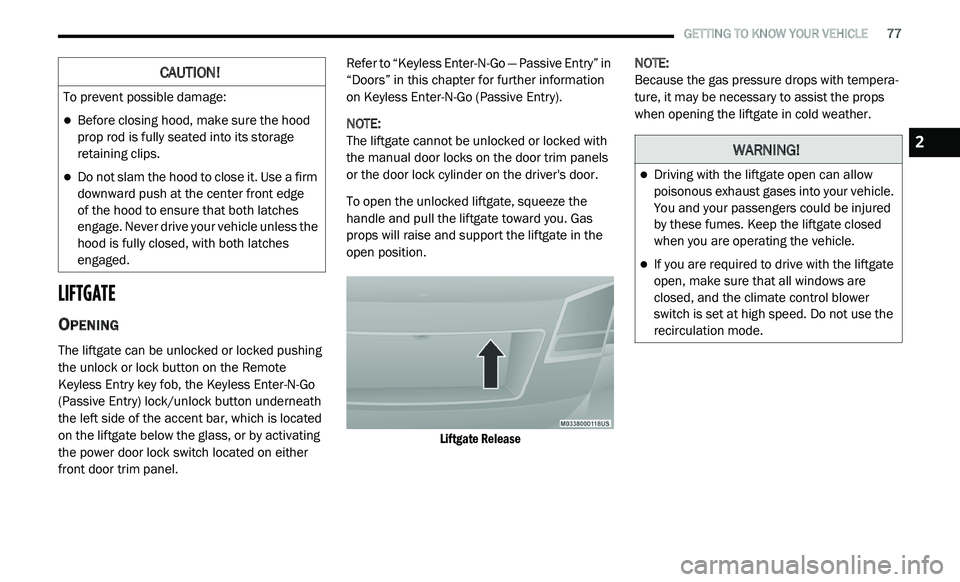
To open the unlocked liftgate, squeeze the
h a
ndle and pull the liftgate toward you. Gas
props will raise and support the liftgate in the
open position.
Liftgate Release
NOTE:
Because the gas pressure drops with tempera -
ture, it may be necessary to assist the props
w h
en opening the liftgate in cold weather.
CAUTION!
To prevent possible damage:
Before closing hood, make sure the hood
prop rod is fully seated into its storage
retaining clips.
Do not slam the hood to close it. Use a firm
downward push at the center front edge
of the hood to ensure that both latches
e n
gage. Never drive your vehicle unless the
hood is fully closed, with both latches
engaged.
WARNING!
Driving with the liftgate open can allow
poisonous exhaust gases into your vehicle.
You and your passengers could be injured
by these fumes. Keep the liftgate closed
when you are operating the vehicle.
If you are required to drive with the liftgate
open, make sure that all windows are
closed, and the climate control blower
switch is set at high speed. Do not use the
recirculation mode.
2
Page 85 of 396
GETTING TO KNOW YOUR VEHICLE 83
(Continued)
4. Watch for the HomeLink® indicator to change flash rates. When it changes, it is
programmed. It may take up to 30 seconds
or longer in rare cases. The garage door
may open and close while you are
programming.
5. P ush and hold the programmed
H
omeLink® button and observe the
indicator light.
NOTE:
If the indicator light stays on constantly,
programming is complete and the garage
door/device should activate when the
HomeLink® button is pushed.
To program the two remaining HomeLink®
buttons, repeat each step for each remaining
button. DO NOT erase the channels.
If you unplugged the garage door opener/
de
vice for programming, plug it back in at this
time.
USING HOMELINK®
To operate, push and release the programmed
HomeLink® button. Activation will now occur for
the programmed device (i.e. garage door opener,
gate operator, security system, entry door lock,
home/office lighting, etc.) The hand-held
transmitter of the device may also be used at any
time.
SECURITY
It is advised to erase all channels before you sell
or turn in your vehicle.
To do this, push and hold the two outside
b u
ttons for 20 seconds until the red indicator
flashes.
NOTE:
All channels will be erased. Individual channels
ca
nnot be erased.
The HomeLink® Universal Transceiver is disabled
w h
en the vehicle security alarm is active.
TROUBLESHOOTING TIPS
If you are having trouble programming
HomeLink®, here are some of the most
common solutions:
Replace the battery in the garage door
opener hand-held transmitter.
Push the LEARN button on the garage door
opener to complete the training for a Rolling
Code.
Did you unplug the device for programming
and remember to plug it back in?
If you have any problems, or require assistance,
p l
ease call toll-free 1-800-355-3515 or, on the
Internet at HomeLink.com for information or
assistance.
WARNING!
Vehicle exhaust contains carbon monoxide,
a dangerous gas. Do not run your vehicle in
the garage while programming the trans -
ceiver. Exhaust gas can cause serious
i n
jury or death.
2
Page 99 of 396
GETTING TO KNOW YOUR INSTRUMENT PANEL 97
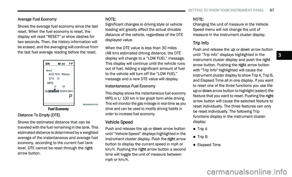
Average Fuel Economy
Shows the average fuel economy since the last
re
set. When the fuel economy is reset, the
display will read “RESET” or show dashes for
two seconds. Then, the history information will
be erased, and the averaging will continue from
the last fuel average reading before the reset.
Fuel Economy
Distance To Empty (DTE)
Shows the estimated distance that can be
t r
aveled with the fuel remaining in the tank. This
estimated distance is determined by a weighted
average of the instantaneous and average fuel
economy, according to the current fuel tank
level. DTE cannot be reset through the right
arrow button. NOTE:
Significant changes in driving style or vehicle
l o
ading will greatly affect the actual drivable
distance of the vehicle, regardless of the DTE
displayed value.
When the DTE value is less than 30 miles
(4
8 km) estimated driving distance, the DTE
d i
splay will change to a “LOW FUEL” message.
This display will continue until the vehicle runs
out of fuel. Adding a significant amount of fuel
to the vehicle will turn off the “LOW FUEL”
message and a new DTE value will display.
Instantaneous Fuel Economy
This display shows the instantaneous fuel economy
M P
G or L/ 100 km in bar graph form while driving.
T h
is will monitor the gas mileage in real-time as you
drive and can be used to modify driving habits in
order to increase fuel economy.
Vehicle Speed
Push and release the up or down arrow button
until “Vehicle Speed” displays highlighted in the
instrument cluster display. Push the right arrow
button to display the current speed in mph or
km/h. Pushing the right arrow button a second
time will toggle the unit of measure between
mph or km/h. NOTE:
Changing the unit of measure in the Vehicle
S p
eed menu will not change the unit of
measure in the instrument cluster display.
Trip Info
Push and release the up or down arrow button
until “Trip Info” displays highlighted in the
instrument cluster display and push the right
arrow button. Pushing the right arrow button
with "Trip Info" highlighted will cause the
instrument cluster display to show Trip A, Trip B,
and Elapsed Time all in one display. If you want
to reset one of the three functions you use the
up or down arrow button to highlight (select) the
feature that you want to reset. Pushing the right
arrow button will cause the selected feature to
reset individually. The three features can only
be reset individually. The following Trip
functions display in the instrument cluster
display:
Trip A
Trip B
Elapsed Time
3
Page 135 of 396
SAFETY 133
Front Air Bag Operation
Front Air Bags are designed to provide
additional protection by supplementing the seat
belts. Front air bags are not expected to reduce
the risk of injury in rear, side, or rollover
collisions. The front air bags will not deploy in all
frontal collisions, including some that may
produce substantial vehicle damage — for
example, some pole collisions, truck
underrides, and angle offset collisions. On the other hand, depending on the type and
l
o
cation of impact, front air bags may deploy in
crashes with little vehicle front-end damage but
that produce a severe initial deceleration.
Because air bag sensors measure vehicle
d e
celeration over time, vehicle speed and
damage by themselves are not good indicators
of whether or not an air bag should have
deployed.
Seat belts are necessary for your protection in
al
l collisions, and also are needed to help keep
you in position, away from an inflating air bag.
When the ORC detects a collision requiring the
f r
ont air bags, it signals the inflator units. A large
quantity of non-toxic gas is generated to inflate
the front air bags.
The steering wheel hub trim cover and the
u p
per passenger side of the instrument panel
separate and fold out of the way as the air bags
inflate to their full size. The front air bags fully
inflate in less time than it takes to blink your
eyes. The front air bags then quickly deflate
while helping to restrain the driver and front
passenger.
Knee Impact Bolsters
The Knee Impact Bolsters help protect the
knees of the driver and front passenger, and
position the front occupants for improved
interaction with the front air bags.
Supplemental Driver Knee Air Bag
This vehicle is equipped with a Supplemental Driver
Knee Air Bag mounted in the instrument panel
below the steering column. The Supplemental
Driver Knee Air Bag provides enhanced protection
during a frontal impact by working together with the
seat belts, pretensioners, and front air bags.
Do not put anything on or around the air
bag covers or attempt to open them manu -
ally. You may damage the air bags and you
c o
uld be injured because the air bags may
no longer be functional. The protective
covers for the air bag cushions are
designed to open only when the air bags
are inflating.
Relying on the air bags alone could lead to
more severe injuries in a collision. The air
bags work with your seat belt to restrain you
properly. In some collisions, air bags won’t
deploy at all. Always wear your seat belts
even though you have air bags.
WARNING! (Continued)
WARNING!
Do not drill, cut, or tamper with the knee
impact bolsters in any way.
Do not mount any accessories to the knee
impact bolsters such as alarm lights,
stereos, citizen band radios, etc.4
Page 139 of 396
SAFETY 137
If you do have a collision which deploys the air
bags, any or all of the following may occur:
The air bag material may sometimes cause
abrasions and/or skin reddening to the occu -
pants as the air bags deploy and unfold. The
a b
rasions are similar to friction rope burns or
those you might get sliding along a carpet or
gymnasium floor. They are not caused by
contact with chemicals. They are not perma -
nent and normally heal quickly. However, if
y o
u haven’t healed significantly within a few
days, or if you have any blistering, see your
doctor immediately.
As the air bags deflate, you may see some
smoke-like particles. The particles are a
normal by-product of the process that gener -
ates the non-toxic gas used for air bag infla -
tion. These airborne particles may irritate the
s k
in, eyes, nose, or throat. If you have skin or
eye irritation, rinse the area with cool water.
For nose or throat irritation, move to fresh air.
If the irritation continues, see your doctor.
If these particles settle on your clothing,
f o
llow the garment manufacturer’s instruc -
tions for cleaning. Do not drive your vehicle after the air bags have
d
e
ployed. If you are involved in another
collision, the air bags will not be in place to
protect you.
NOTE:
Air bag covers may not be obvious in the inte -
rior trim, but they will open during air bag
d e
ployment.
After any collision, the vehicle should be
taken to an authorized dealer immediately.
Enhanced Accident Response System
In the event of an impact, if the communication
network remains intact, and the power remains
intact, depending on the nature of the event,
the ORC will determine whether to have the
Enhanced Accident Response System perform
the following functions:
Cut off fuel to the engine (if equipped)
Cut off battery power to the electric motor
(if equipped)
Flash hazard lights as long as the battery has
power
Turn on the interior lights, which remain on
as long as the battery has power or for
15 minutes from the intervention of the
E n
hanced Accident Response System
Unlock the power door locks
WARNING!
Deployed air bags and seat belt pretensioners
cannot protect you in another collision. Have
the air bags, seat belt pretensioners, and the
seat belt retractor assemblies replaced by an
authorized dealer immediately. Also, have the
Occupant Restraint Controller System serviced
as well.
4
Page 156 of 396
154 SAFETY
(Continued)
(Continued)
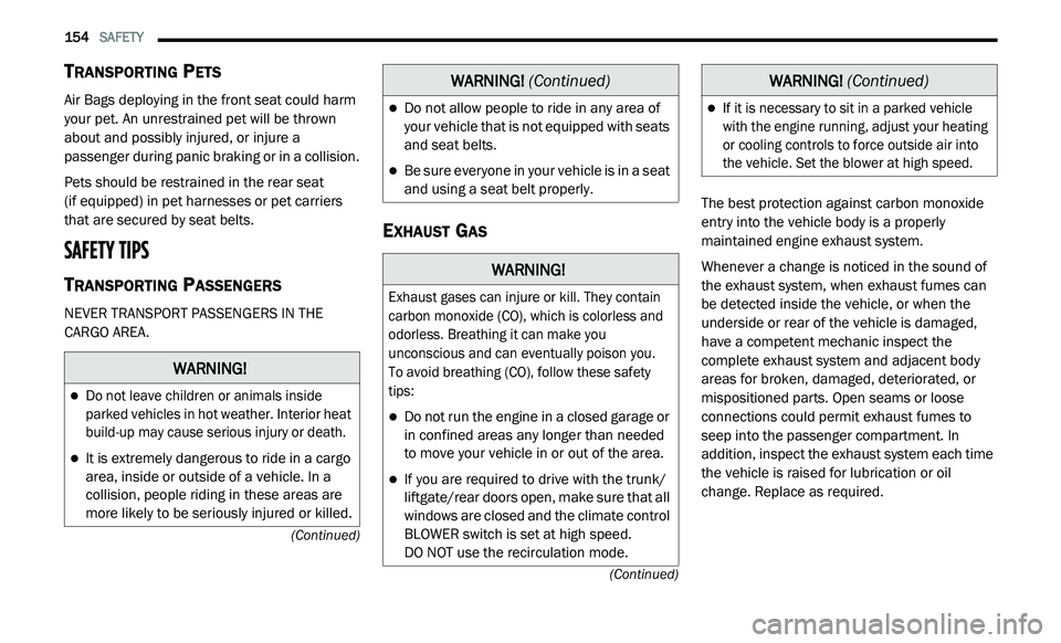
TRANSPORTING PETS
Air Bags deploying in the front seat could harm
your pet. An unrestrained pet will be thrown
about and possibly injured, or injure a
passenger during panic braking or in a collision.
Pets should be restrained in the rear seat
(if equipped) in pet harnesses or pet carriers
th
at are secured by seat belts.
SAFETY TIPS
TRANSPORTING PASSENGERS
NEVER TRANSPORT PASSENGERS IN THE
CARGO AREA.
EXHAUST GAS
The best protection against carbon monoxide
entry into the vehicle body is a properly
maintained engine exhaust system.
Whenever a change is noticed in the sound of
th
e exhaust system, when exhaust fumes can
be detected inside the vehicle, or when the
underside or rear of the vehicle is damaged,
have a competent mechanic inspect the
complete exhaust system and adjacent body
areas for broken, damaged, deteriorated, or
mispositioned parts. Open seams or loose
connections could permit exhaust fumes to
seep into the passenger compartment. In
addition, inspect the exhaust system each time
the vehicle is raised for lubrication or oil
change. Replace as required.
WARNING!
Do not leave children or animals inside
parked vehicles in hot weather. Interior heat
build-up may cause serious injury or death.
It is extremely dangerous to ride in a cargo
area, inside or outside of a vehicle. In a
collision, people riding in these areas are
more likely to be seriously injured or killed.
Do not allow people to ride in any area of
your vehicle that is not equipped with seats
and seat belts.
Be sure everyone in your vehicle is in a seat
and using a seat belt properly.
WARNING!
Exhaust gases can injure or kill. They contain
carbon monoxide (CO), which is colorless and
odorless. Breathing it can make you
unconscious and can eventually poison you.
To avoid breathing (CO), follow these safety
t i
ps:
Do not run the engine in a closed garage or
in confined areas any longer than needed
to move your vehicle in or out of the area.
If you are required to drive with the trunk/
liftgate/rear doors open, make sure that all
windows are closed and the climate control
BLOWER switch is set at high speed.
DO NOT use the recirculation mode.
WARNING! (Continued)
If it is necessary to sit in a parked vehicle
with the engine running, adjust your heating
or cooling controls to force outside air into
the vehicle. Set the blower at high speed.
WARNING! (Continued)
Page 158 of 396
156 SAFETY
(Continued)
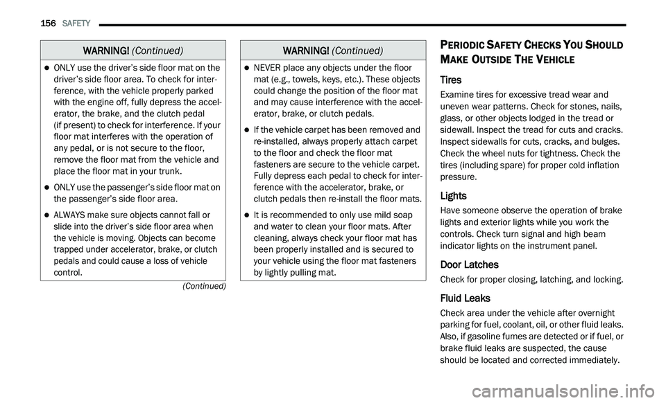
PERIODIC SAFETY CHECKS YOU SHOULD
M
AKE OUTSIDE THE VEHICLE
Tires
Examine tires for excessive tread wear and
uneven wear patterns. Check for stones, nails,
glass, or other objects lodged in the tread or
sidewall. Inspect the tread for cuts and cracks.
Inspect sidewalls for cuts, cracks, and bulges.
Check the wheel nuts for tightness. Check the
tires (including spare) for proper cold inflation
pressure.
Lights
Have someone observe the operation of brake
lights and exterior lights while you work the
controls. Check turn signal and high beam
indicator lights on the instrument panel.
Door Latches
Check for proper closing, latching, and locking.
Fluid Leaks
Check area under the vehicle after overnight
parking for fuel, coolant, oil, or other fluid leaks.
Also, if gasoline fumes are detected or if fuel, or
brake fluid leaks are suspected, the cause
should be located and corrected immediately.
ONLY use the driver’s side floor mat on the
driver’s side floor area. To check for inter -
ference, with the vehicle properly parked
w i
th the engine off, fully depress the accel -
erator, the brake, and the clutch pedal
(if present) to check for interference. If your
f l
oor mat interferes with the operation of
any pedal, or is not secure to the floor,
remove the floor mat from the vehicle and
place the floor mat in your trunk.
ONLY use the passenger’s side floor mat on
the passenger’s side floor area.
ALWAYS make sure objects cannot fall or
slide into the driver’s side floor area when
the vehicle is moving. Objects can become
trapped under accelerator, brake, or clutch
pedals and could cause a loss of vehicle
control.
WARNING! (Continued)
NEVER place any objects under the floor
mat (e.g., towels, keys, etc.). These objects
could change the position of the floor mat
and may cause interference with the accel -
erator, brake, or clutch pedals.
If the vehicle carpet has been removed and
re-installed, always properly attach carpet
to the floor and check the floor mat
fasteners are secure to the vehicle carpet.
Fully depress each pedal to check for inter -
ference with the accelerator, brake, or
c lu
tch pedals then re-install the floor mats.
It is recommended to only use mild soap
and water to clean your floor mats. After
cleaning, always check your floor mat has
been properly installed and is secured to
your vehicle using the floor mat fasteners
by lightly pulling mat.
WARNING! (Continued)