ECO mode DODGE JOURNEY 2020 Owner's Guide
[x] Cancel search | Manufacturer: DODGE, Model Year: 2020, Model line: JOURNEY, Model: DODGE JOURNEY 2020Pages: 396, PDF Size: 25.53 MB
Page 122 of 396
120 SAFETY
General Information
The following regulatory statement applies to all
Radio Frequency (RF) devices equipped in this
vehicle:
This device complies with Part 15 of the FCC
Ru
les and with Innovation, Science and
Economic Development Canada license-exempt
RSS standard(s). Operation is subject to the
following two conditions:
1. T his device may not cause harmful
i
nterference, and
2. T his device must accept any interference
r
eceived, including interference that may
cause undesired operation.
Le présent appareil est conforme aux CNR
d`
Innovation, Science and Economic
Development applicables aux appareils radio
exempts de licence. L'exploitation est autorisée
aux deux conditions suivantes:
1. l 'appareil ne doit pas produire de
b
rouillage, et
2. l
'utilisateur de l'appareil doit accepter tout
b
rouillage radioélectrique subi, même si le
brouillage est susceptible d'en compro -
mettre le fonctionnement.
La operación de este equipo está sujeta a las
s i
guientes dos condiciones:
1. e s posible que este equipo o dispositivo no
c
ause interferencia perjudicial y
2. e ste equipo o dispositivo debe aceptar
c
ualquier interferencia, incluyendo la que
pueda causar su operación no deseada.
NOTE:
Changes or modifications not expressly
a p
proved by the party responsible for compli -
ance could void the user’s authority to operate
t h
e equipment.
OCCUPANT RESTRAINT SYSTEMS
Some of the most important safety features in
your vehicle are the restraint systems:
OCCUPANT RESTRAINT SYSTEMS
F
EATURES
Some of the most important safety features in
your vehicle are the restraint systems:
Seat Belt Systems
Supplemental Restraint Systems (SRS) Air Bags
Supplemental Active Head Restraints
Child Restraints
Some of the safety features described in this
s e
ction may be standard equipment on some
models, or may be optional equipment on
others. If you are not sure, ask an authorized
dealer.
Page 153 of 396
SAFETY 151
Installing A Child Restraint With A
Switchable Automatic Locking
Retractor (ALR):
Child restraint systems are designed to be
secured in vehicle seats by lap belts or the lap
belt portion of a lap/shoulder belt.
1. Place the child seat in the center of the
s
eating position. If the second row seat can
be reclined, you may recline the seat and/or
raise the head restraint (if adjustable) to get
a better fit. If the rear seat can be moved
forward and rearward in the vehicle, you may
wish to move it to its rear-most position to
make room for the child seat. You may also
move the front seat forward to allow more
room for the child seat.
2. P
ull enough of the seat belt webbing from
t
he retractor to pass it through the belt path
of the child restraint. Do not twist the belt
webbing in the belt path.
3. Slide the latch plate into the buckle until you h
ear a “click.”
4. P ull on the webbing to make the lap portion
t
ight against the child seat.
5. T o lock the seat belt, pull down on the
s
houlder part of the belt until you have
pulled all the seat belt webbing out of the
retractor. Then, allow the webbing to retract
back into the retractor. As the webbing
retracts, you will hear a clicking sound.
This means the seat belt is now in the
A u
tomatic Locking mode.
6. T ry to pull the webbing out of the retractor.
I
f it is locked, you should not be able to pull
out any webbing. If the retractor is not
locked, repeat step 5.
7. Finally, pull up on any excess webbing to tighten the lap portion around the child restraint while
you push the child restraint rearward and
downward into the vehicle seat.
8. If the child restraint has a top tether strap a
nd the seating position has a top tether
anchorage, connect the tether strap to the
anchorage and tighten the tether strap.
See the section “Installing Child Restraints
U s
ing the Top Tether Anchorage” for
directions to attach a tether anchor.
9. T est that the child restraint is installed
t
ightly by pulling back and forth on the child
seat at the belt path. It should not move
more than 1 inch (25.4 mm) in any
d i
rection.
Any seat belt system will loosen with time, so
c h
eck the belt occasionally, and pull it tight if
necessary.
WARNING!
Improper installation or failure to properly
secure a child restraint can lead to failure
of the restraint. The child could be badly
injured or killed.
Follow the child restraint manufacturer’s
directions exactly when installing an infant
or child restraint.
4
Page 157 of 396
SAFETY 155
(Continued)
SAFETY CHECKS YOU SHOULD MAKE
I
NSIDE THE VEHICLE
Seat Belts
Inspect the seat belt system periodically,
checking for cuts, frays, and loose parts.
Damaged parts must be replaced immediately.
Do not disassemble or modify the system.
Front seat belt assemblies must be replaced
a f
ter a collision. Rear seat belt assemblies must
be replaced after a collision if they have been
damaged (i.e., bent retractor, torn webbing,
etc.). If there is any question regarding seat belt
or retractor condition, replace the seat belt.
Air Bag Warning Light
The Air Bag warning light will turn on for
four to eight seconds as a bulb check when the
i g
nition switch is first turned to ON/RUN. If the
light is either not on during starting, stays on,
or turns on while driving, have the system
i n
spected at an authorized dealer as soon as
possible. After the bulb check, this light will
illuminate with a single chime when a fault with
the Air Bag System has been detected. It will stay on until the fault is removed. If the light
comes on intermittently or remains on while
driving, have an authorized dealer service the
vehicle immediately.
Refer to “Occupant Restraint Systems” in
“
S
afety” for further information.
Defroster
Check operation by selecting the defrost mode
and place the blower control on high speed. You
should be able to feel the air directed against
the windshield. See an authorized dealer for
service if your defroster is inoperable.
Floor Mat Safety Information
Always use floor mats designed to fit your
vehicle. Only use a floor mat that does not
interfere with the operation of the accelerator,
brake or clutch pedals. Only use a floor mat that
is securely attached using the floor mat
fasteners so it cannot slip out of position and
interfere with the accelerator, brake or clutch
pedals or impair safe operation of your vehicle
in other ways.
WARNING!
An improperly attached, damaged, folded, or
stacked floor mat, or damaged floor mat
fasteners may cause your floor mat to
interfere with the accelerator, brake, or clutch
pedals and cause a loss of vehicle control.
To prevent SERIOUS INJURY or DEATH:
ALWAYS securely attach your floor mat
using the floor mat fasteners. DO NOT
i n
stall your floor mat upside down or turn
your floor mat over. Lightly pull to confirm
mat is secured using the floor mat
fasteners on a regular basis.
ALWAYS REMOVE THE EXISTING FLOOR
MAT FROM THE VEHICLE before
installing any other floor mat. NEVER install
o r
stack an additional floor mat on top of an
existing floor mat.
ONLY install floor mats designed to fit your
vehicle. NEVER install a floor mat that
cannot be properly attached and secured to
your vehicle. If a floor mat needs to be
replaced, only use a FCA approved floor
mat for the specific make, model, and year
of your vehicle.
4
Page 160 of 396
158 STARTING AND OPERATING
NORMAL STARTING
To Turn On The Engine Using The ENGINE
START/STOP Button
1. T he transmission must be in PARK.
2
. P ress and hold the brake pedal while pushing
t
he ENGINE START/STOP button once.
3. T he system takes over and attempts to start
t
he vehicle. If the vehicle fails to start, the
starter will disengage automatically after
10 seconds.
4. If you wish to stop the cranking of the e
ngine prior to the engine starting, push the
ENGINE START/STOP button again.
NOTE:
Normal starting of either a cold or a warm
e n
gine is obtained without pumping or pressing
the accelerator pedal.
To Turn Off The Engine Using ENGINE
START/STOP Button
1. P lace the gear selector in PARK, then push
a
nd release the ENGINE START/STOP
button.
2. T he ignition will return to the OFF mode. 3
. I
f the gear selector is not in PARK, the
E
NGINE START/STOP button must be held
for two seconds or three short pushes in a
row with the vehicle speed above 5 mph
( 8
km/h) before the engine will shut off.
The ignition will remain in the ACC mode
u n
til the gear selector is in PARK and the
button is pushed twice to the OFF mode.
If the gear selector is not in PARK and the
E N
GINE START/STOP button is pushed
once, the instrument cluster will display a
“Vehicle Not In Park” message and the
engine will remain running. Never leave a
vehicle out of the PARK position, or it
could roll.
NOTE:
If the gear selector is in NEUTRAL, push and
r e
lease the ENGINE START/STOP button with
the vehicle speed below 5 mph (8 km/h) before
t h
e engine will shut off, and the ignition will
remain in the ACC position. The system will
automatically time out and the ignition will cycle
to the OFF mode after 30 minutes of inactivity if
t h
e ignition is left in the ACC or RUN (engine not
running) mode and the transmission is in PARK. ENGINE START/STOP Button Functions — With
D
r
iver’s Foot OFF The Brake Pedal (In PARK Or
NEUTRAL Position)
The ENGINE START/STOP button operates
s i
milar to an ignition switch. It has three modes:
OFF, ACC, and RUN. To change the ignition
modes without starting the vehicle and use the
accessories, follow these directions:
1. S tart with the ignition in the OFF mode.
2
. P ush the ENGINE START/STOP button once
t
o place the ignition to the ACC mode.
3. P ush the ENGINE START/STOP button a
s
econd time to place the ignition to the RUN
mode.
4. P ush the ENGINE START/STOP button a
t
hird time to return the ignition to the OFF
mode.
KEYLESS ENTER-N-GO — IGNITION
This feature allows the driver to operate the
ignition switch with the push of a button, as long
as the Remote Start/Keyless Enter-N-Go key
fob is in the passenger compartment.
Page 162 of 396
160 STARTING AND OPERATING
ENGINE BREAK-IN RECOMMENDATIONS
A long break-in period is not required for the
engine and drivetrain (transmission and axle) in
your vehicle.
Drive moderately during the first 300 miles
( 5
00 km). After the initial 60 miles (100 km),
s p
eeds up to 50 or 55 mph (80 or 90 km/h) are
d e
sirable.
While cruising, brief full-throttle acceleration
w i
thin the limits of local traffic laws contributes
to a good break-in. Wide-open throttle
acceleration in low gear can be detrimental and
should be avoided.
The engine oil installed in the engine at the
fa
ctory is a high-quality energy conserving
type lubricant. Oil changes should be consistent
w i
th anticipated climate conditions under which
vehicle operations will occur. For the
recommended viscosity and quality grades,
refer to “Fluids And Lubricants” in “Technical
Specifications”. NOTE:
A new engine may consume some oil during its
fi
rst few thousand miles (kilometers) of opera -
tion. This should be considered a normal part of
t h
e break-in and not interpreted as a problem.
Please check your oil level with the engine oil
indicator often during the break in period. Add
oil as required.
PARKING BRAKE
Before exiting the vehicle, make sure that the
parking brake is fully applied. Also, be certain to
leave the transmission in PARK.
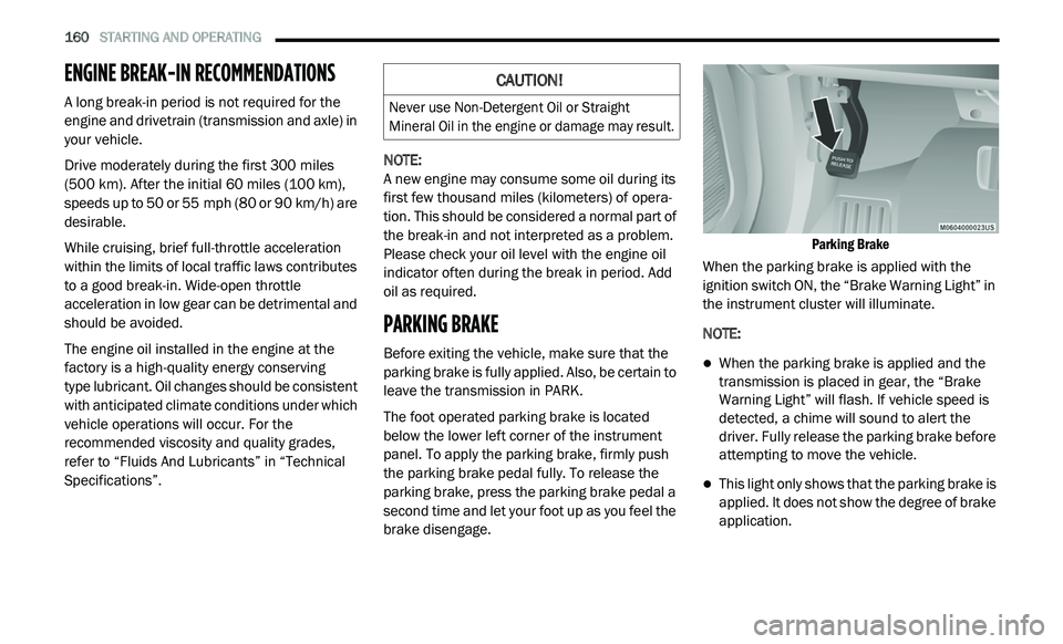
The foot operated parking brake is located
b e
low the lower left corner of the instrument
panel. To apply the parking brake, firmly push
the parking brake pedal fully. To release the
parking brake, press the parking brake pedal a
second time and let your foot up as you feel the
brake disengage.
Parking Brake
When the parking brake is applied with the
i g
nition switch ON, the “Brake Warning Light” in
the instrument cluster will illuminate.
NOTE:
When the parking brake is applied and the
transmission is placed in gear, the “Brake
Warning Light” will flash. If vehicle speed is
detected, a chime will sound to alert the
driver. Fully release the parking brake before
attempting to move the vehicle.
This light only shows that the parking brake is
applied. It does not show the degree of brake
application.
CAUTION!
Never use Non-Detergent Oil or Straight
Mineral Oil in the engine or damage may result.
Page 168 of 396
![DODGE JOURNEY 2020 Owners Guide
166 STARTING AND OPERATING
(-16°F [-27°C] or below), operation may briefly
be limited to only second gear. Normal
operation will resume once the transmission
temperature has risen to a su DODGE JOURNEY 2020 Owners Guide
166 STARTING AND OPERATING
(-16°F [-27°C] or below), operation may briefly
be limited to only second gear. Normal
operation will resume once the transmission
temperature has risen to a su](/img/12/40495/w960_40495-167.png)
166 STARTING AND OPERATING
(-16°F [-27°C] or below), operation may briefly
be limited to only second gear. Normal
operation will resume once the transmission
temperature has risen to a suitable level.
AutoStick
AutoStick is a driver-interactive transmission
feature providing manual shift control, giving
you more control of the vehicle. AutoStick allows
y o
u to maximize engine braking, eliminate
undesirable upshifts and downshifts, and
improve overall vehicle performance. This system
can also provide you with more control during
passing, city driving, cold slippery conditions,
mountain driving, trailer towing, and many other
situations.
Operation
When the gear selector is in the AutoStick
p o
sition (below the DRIVE position), it can be
moved from side to side. This allows the driver
to manually select the transmission gear being
used. Moving the gear selector to the left (-)
triggers a downshift and to the right (+) an
upshift. The current gear will be displayed in the
instrument cluster. In AutoStick mode, the transmission will shift up
o
r
down when the driver moves the gear
selector to the right (+) or left (-), unless an
engine lugging or overspeed condition would
result. It will remain in the selected gear until
another upshift or downshift is chosen, except
as described below.
The transmission will automatically upshift
when necessary to prevent engine
over-speed.
The transmission will automatically down -
shift as the vehicle slows (to prevent engine
l u
gging) and will display the current gear.
The transmission will automatically downshift
to first gear when coming to a stop. After a
stop, the driver should manually upshift (+) the
transmission as the vehicle is accelerated.
You can start out, from a stop, in any gear
except top gear. Tapping (+) (at a stop) will
allow starting in SECOND gear. Starting out in
SECOND gear can be helpful in snowy or icy
conditions.
If a requested downshift would cause the
engine to over-speed, that shift will not occur.
Avoid using speed control when AutoStick is
engaged.
Transmission shifting will be more noticeable
when AutoStick is enabled.
The system may revert to automatic shift
mode if a fault or overheat condition is
detected.
To disengage AutoStick mode, return the gear
s e
lector to the DRIVE position. You can shift in or
out of the AutoStick position at any time without
taking your foot off the accelerator pedal.
WARNING!
Do not downshift for additional engine braking
on a slippery surface. The drive wheels could
lose their grip and the vehicle could skid,
causing a collision or personal injury.
Page 169 of 396
STARTING AND OPERATING 167
Transmission Limp Home Mode
Transmission function is monitored
electronically for abnormal conditions. If a
condition is detected that could result in
transmission damage, Transmission Limp
Home Mode is activated. In this mode, the
transmission remains in SECOND gear
regardless of which forward gear is selected.
PARK, REVERSE, and NEUTRAL will continue to
operate. The Malfunction Indicator Light (MIL)
may be illuminated. Limp Home Mode allows
the vehicle to be driven to an authorized dealer
for service without damaging the transmission.
In the event of a momentary problem, the
tr
ansmission can be reset to regain all forward
gears by performing the following steps:
1. S top the vehicle.
2
. S hift the transmission into PARK.
3
. T urn the ignition OFF.
4
. W ait approximately 10 seconds.
5
. R estart the engine.
6
. S hift into the desired gear range. If the
p
roblem is no longer detected, the
transmission will return to normal operation.
NOTE:
Even if the transmission can be reset, we
r e
commend that you visit an authorized dealer
at your earliest possible convenience. An autho -
rized dealer has diagnostic equipment to
a s
sess the condition of your transmission.
If the transmission cannot be reset, authorized
d e
aler service is required.
Overdrive Operation
The automatic transmission includes an
electronically controlled Overdrive (top gear).
The transmission will automatically shift into
Overdrive if the following conditions are
present:
The gear selector is in the DRIVE position.
The transmission fluid has reached an
adequate temperature.
The engine coolant has reached an adequate
temperature.
The vehicle speed is sufficiently high.
The driver is not heavily pressing the acceler -
ator.
Torque Converter Clutch
A feature designed to improve fuel economy
has been included in the automatic
transmission on your vehicle. A clutch within the
torque converter engages automatically at
calibrated speeds. This may result in a slightly
different feeling or response during normal
operation in the upper gears. When the vehicle
speed drops or during some accelerations, the
clutch automatically disengages.
NOTE:
The torque converter clutch will not engage until
t h
e transmission fluid and engine coolant are
warm (usually after 1 to 3 miles [2 to 5 km] of
d r
iving). Because the engine speed is higher
when the torque converter clutch is not
engaged, it may seem as if the transmission is
not shifting into Overdrive when cold. This is
normal. Using the AutoStick shift control, when
the transmission is sufficiently warm, will
demonstrate that the transmission is able to
shift into and out of Overdrive.
5
Page 177 of 396
STARTING AND OPERATING 175
(Continued)
PARKVIEW REAR BACK UP CAMERA
Your vehicle is equipped with the ParkView Rear
Back Up Camera that allows you to see an
on-screen image of the rear surroundings of
your vehicle whenever the gear selector is put
into REVERSE. The image will be displayed in
the touchscreen display along with a caution
note to “Check Entire Surroundings” across the
top of the screen. After five seconds this note
will disappear. The ParkView camera is located
on the rear of the vehicle above the rear license
plate.
When the vehicle is shifted out of REVERSE, the
r e
ar camera mode is exited and the last
selected touchscreen appears again.
The camera image is also available in the
r e
arview mirror if the touchscreen display is
unavailable. If your vehicle is equipped with the Camera
D
e
lay feature and it is turned on, the rear
camera image will be displayed for up to
10 seconds when the vehicle is shifted out of
R E
VERSE unless the forward vehicle speed
exceeds 8 mph (13 km/h), the transmission is
s h
ifted into PARK, the “X” button on the camera
display screen is pressed, or the vehicle's
ignition is placed in the OFF position.
Static grid lines will illustrate the width of the
v e
hicle. These lines will show separate zones
that will help indicate the distance to the rear of
the vehicle.
NOTE:
The ParkView Rear Back Up Camera has
p r
ogrammable modes of operation that may be
selected through the Uconnect system. Refer to
“Uconnect Settings” in “Multimedia” for further
information.
Different colored zones indicate the distance to
t h
e rear of the vehicle.
Before using ParkSense, it is strongly
recommended that the ball mount and
hitch ball assembly is disconnected from
the vehicle when the vehicle is not used for
towing. Failure to do so can result in injury
or damage to vehicles or obstacles
because the hitch ball will be much closer
to the obstacle than the rear fascia when
the loudspeaker sounds the continuous
tone. Also, the sensors could detect the ball
mount and hitch ball assembly, depending
on its size and shape, giving a false indica -
tion that an obstacle is behind the vehicle.
CAUTION!
ParkSense is only a parking aid and it is
unable to recognize every obstacle,
including small obstacles. Parking curbs
might be temporarily detected or not
detected at all. Obstacles located above or
below the sensors will not be detected
when they are in close proximity.
WARNING! (Continued)
The vehicle must be driven slowly when
using ParkSense in order to be able to stop
in time when an obstacle is detected. It is
recommended that the driver looks over
his/her shoulder when using ParkSense.
CAUTION! (Continued)
5
Page 213 of 396

IN CASE OF EMERGENCY 211
FREEING A STUCK VEHICLE
If your vehicle becomes stuck in mud, sand, or
snow, it can often be moved using a rocking motion.
Turn the steering wheel right and left to clear the
area around the front wheels. Then, shift back and
forth between DRIVE (D) and REVERSE (R) while
gently pressing the accelerator. Use the least
amount of accelerator pedal pressure that will
maintain the rocking motion, without spinning the
wheels or racing the engine.
Push the ESC OFF switch, to place the
Electronic Stability Control (ESC)
s
y
stem in "ESC Partial Off" mode,
before rocking the vehicle. Refer to
“Electronic Brake Control System” in “Safety”
for further information. Once the vehicle has
been freed, push the ESC OFF switch again to
restore "ESC On" mode.
CAUTION!
Racing the engine or spinning the wheels may
lead to transmission overheating and failure.
Allow the engine to idle with the transmission
in NEUTRAL for at least one minute after
every five rocking-motion cycles. This will
minimize overheating and reduce the risk of
transmission failure during prolonged efforts
to free a stuck vehicle.
WARNING!
Fast spinning tires can be dangerous. Forces
generated by excessive wheel speeds may
cause damage, or even failure, of the axle
and tires. A tire could explode and injure
someone. Do not spin your vehicle's wheels
faster than 30
mph (48 km/h) or for longer
t h
an 30 seconds continuously without
stopping when you are stuck and do not let
anyone near a spinning wheel, no matter
what the speed.
CAUTION!
When “rocking” a stuck vehicle by shifting
between DRIVE and REVERSE, do not spin
the wheels faster than 15 mph (24 km/h),
o r
drivetrain damage may result.
Revving the engine or spinning the wheels
too fast may lead to transmission over -
heating and failure. It can also damage the
t i
res. Do not spin the wheels above 30 mph
( 4
8 km/h) while in gear (no transmission
s h
ifting occurring).
6
Page 215 of 396
IN CASE OF EMERGENCY 213
FRONT-WHEEL DRIVE (FWD) MODELS
The manufacturer recommends towing your
vehicle with all four wheels OFF the ground
using a flatbed.
If flatbed equipment is not available, and the
t r
ansmission is operable, the vehicle may be
flat towed (with all four wheels on the ground)
under the following conditions:
The transmission must be in NEUTRAL.
The towing distance must not exceed
15 miles (24 km).
The towing speed must not exceed 25 mph
(4
0 km/h). If the transmission is not operable, or the
v
e
hicle must be towed faster than 25 mph
( 4
0 km/h) or farther than 15 miles (24 km), it
m u
st be towed with the front wheels OFF the
ground (using a flatbed truck, towing dolly, or
wheel lift equipment with the front wheels
raised).
TOW EYE USAGE — IF EQUIPPED
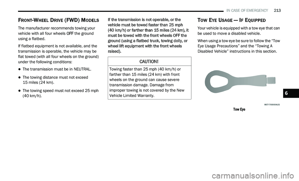
Your vehicle is equipped with a tow eye that can
be used to move a disabled vehicle.
When using a tow eye be sure to follow the “Tow
E y
e Usage Precautions” and the “Towing A
Disabled Vehicle” instructions in this section.
Tow Eye
CAUTION!
Towing faster than 25 mph (40 km/h) or
fa
rther than 15 miles (24 km) with front
w h
eels on the ground can cause severe
transmission damage. Damage from
improper towing is not covered by the New
Vehicle Limited Warranty.
6