oil light DODGE JOURNEY 2020 Owners Manual
[x] Cancel search | Manufacturer: DODGE, Model Year: 2020, Model line: JOURNEY, Model: DODGE JOURNEY 2020Pages: 396, PDF Size: 25.53 MB
Page 13 of 396
GETTING TO KNOW YOUR VEHICLE 11
Using The Panic Alarm
To turn the Panic Alarm feature on or off, push
the Panic button on the key fob. When the Panic
Alarm is activated, the turn signals will flash, the
horn will pulse on and off, and the interior lights
will turn on.
The Panic Alarm will stay on for three minutes
un
less you turn it off by either pushing the Panic
button a second time or drive the vehicle at a
speed of 15 mph (24 km/h) or greater.
NOTE:
The interior lights will turn off if you place the
ignition in the ACC or ON/RUN position while
the Panic Alarm is activated. However, the
exterior lights and horn will remain on.
You may need to be less than 35 ft (11 m)
fr
om the vehicle when using the key fob to
turn off the Panic Alarm due to the radio
frequency noises emitted by the system.
Key Fob Battery Replacement
The recommended replacement battery is one
CR2032 battery.
NOTE:
Perchlorate Material – special handling may
apply. See www.dtsc.ca.gov/hazard -
ouswaste/perchlorate .
Do not touch the battery terminals that are
on the back housing or the printed circuit
board.
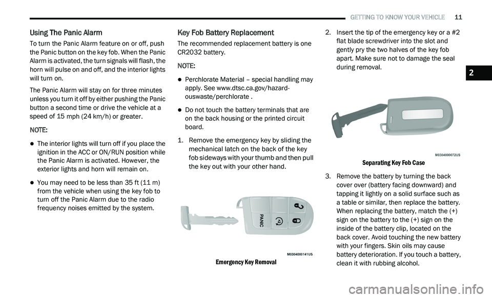
1. R emove the emergency key by sliding the
m
echanical latch on the back of the key
fob sideways with your thumb and then pull
the key out with your other hand.
Emergency Key Removal
2. I
nsert the tip of the emergency key or a #2
f
lat blade screwdriver into the slot and
gently pry the two halves of the key fob
apart. Make sure not to damage the seal
during removal.
Separating Key Fob Case
3. R emove the battery by turning the back
c
over over (battery facing downward) and
tapping it lightly on a solid surface such as
a table or similar, then replace the battery.
When replacing the battery, match the (+)
sign on the battery to the (+) sign on the
inside of the battery clip, located on the
back cover. Avoid touching the new battery
with your fingers. Skin oils may cause
battery deterioration. If you touch a battery,
clean it with rubbing alcohol.
2
Page 98 of 396
96 GETTING TO KNOW YOUR INSTRUMENT PANEL
Right Arrow Button
Push and release the ri
ght arrow
button for access to main menus or
s u
bmenus. Push and hold the right
arrow button for two seconds to
reset features.
Back Button
Push and release the BA
CK button
to scroll back to a previous menu.
OIL CHANGE DUE
Your vehicle is equipped with an engine oil
change indicator system. The “Oil Change Due”
message will appear in the instrument cluster
display for five seconds after a single chime has
sounded to indicate the next scheduled oil
change interval. The engine oil change indicator
system is duty cycle based, which means the
engine oil change interval may fluctuate
dependent upon your personal driving style. Unless reset, this message will continue to
d
i
splay each time you cycle the ignition to the
ON/RUN position. To turn off the message
temporarily, push and release the up arrow
button. To reset the oil change indicator system
(after performing the scheduled maintenance),
perform the following procedure:
1. W ithout pushing the brake pedal, push and
r
elease the ENGINE START/STOP button
and cycle the ignition to the ON/RUN
position (do not start the engine).
2. Fully push the accelerator pedal, slowly, t
hree times within 10 seconds.
3. W ithout pushing the brake pedal, push and
r
elease the ENGINE START/STOP button
once to return the ignition to the OFF/LOCK
position.
NOTE:
If the indicator message illuminates when you
s t
art the vehicle, the oil change indicator system
did not reset. If necessary, repeat this procedure.
INSTRUMENT CLUSTER DISPLAY
S
ELECTABLE MENU ITEMS
Push and release the up or down arrow button
until the desired Selectable Menu item is
displayed in the instrument cluster display.
Follow the Menu or submenu prompts as
d e
sired.
Fuel Economy
Push and release the up or down arrow button
until “Fuel Economy” displays highlighted in the
instrument cluster display and push the right
arrow button. The following Fuel Economy
functions will display in the instrument cluster
display:
Average Fuel Economy
Distance To Empty (DTE)
Instantaneous Fuel Economy
Page 100 of 396
98 GETTING TO KNOW YOUR INSTRUMENT PANEL
The Trip Functions mode displays the following
information:
Trip A
Shows the total distance traveled for Trip A
since the last reset.
Shows the elapsed time traveled for Trip A
since the last reset.
Trip B
Shows the total distance traveled for Trip B
since the last reset.
Shows the elapsed time traveled for Trip B
since the last reset.
Elapsed Time
Shows the total elapsed time of travel since the
l a
st reset. Elapsed time will increment when the
ignition is in the ON/RUN position.
To Reset The Display
Reset will only occur while a resettable function
i s
being displayed. Push and release the right
arrow button once to clear the resettable
function.
Tire Pressure
Push and release the up or down arrow button
until “Tire PSI:” displays highlighted in the
instrument cluster display. Push and release
the right arrow button to view a graphic of the
vehicle with a tire pressure value at each corner
of the graphic.
Vehicle Info (Customer Information
Features)
Push and release the up or down arrow button
until “Vehicle Info” displays in the instrument
cluster display and push the right arrow button.
Push the up or down arrow button to scroll
through the available information displays.
Coolant Temperature
Displays the actual coolant temperature.
Oil Temperature
Displays the actual oil temperature.
Oil Pressure - If Equipped
Displays the actual oil pressure.
Transmission Temperature
Displays the actual transmission temperature.
Engine Hours
Displays the number of hours of engine operation.
Messages
Push and release the up or down arrow button
until “Messages: XX” displays highlighted in the
instrument cluster display. If there is more than
one message, pushing the right arrow button
will display a stored warning message. Push
and release the up or down arrow button if there
is more than one message to cycle through the
remaining stored messages. If there are no
messages, pushing the right arrow button will
not change the display.
Turn Menu OFF
Select from the Main Menu using the up or
down arrow button. Pushing the right arrow
button clears the menu display. Pushing any
one of the four Display control buttons will bring
the menu back.
Page 104 of 396
102 GETTING TO KNOW YOUR INSTRUMENT PANEL
If the temperature reading does not return to
normal, turn the engine off immediately and call
for service.
Refer to “If Your Engine Overheats” in “In Case
Of
Emergency” for further information.
Transmission Temperature Warning Light
— If Equipped
This warning light will illuminate to
warn of a high transmission fluid
te
mperature. This may occur with
strenuous usage such as trailer
towing. If this light turns on, stop the vehicle and
run the engine at idle or slightly faster, with the
transmission in PARK or NEUTRAL, until the
light turns off. Once the light turns off, you may
continue to drive normally.
Battery Charge Warning Light
This warning light will illuminate when
the battery is not charging properly. If
i t
stays on while the engine is running,
there may be a malfunction with the
charging system. Contact an authorized dealer
as soon as possible.
This indicates a possible problem with the
e l
ectrical system or a related component.
Oil Pressure Warning Light
This warning light will illuminate to
indicate low engine oil pressure. If the
li
ght turns on while driving, stop the
vehicle, shut off the engine as soon as
possible, and contact an authorized dealer.
A chime will sound when this light turns on.
Do not operate the vehicle until the cause is
c o
rrected. This light does not indicate how
much oil is in the engine. The engine oil level
must be checked under the hood.
Electronic Throttle Control (ETC) Warning
Light
This warning light will illuminate to
indicate a problem with the Electronic
T h
rottle Control (ETC) system. If a
problem is detected while the vehicle is
running, the light will either stay on or flash
depending on the nature of the problem. Cycle the
ignition when the vehicle is safely and completely
stopped and the transmission is placed in the PARK
position. The light should turn off. If the light
remains on with the vehicle running, your vehicle
will usually be drivable; however, see an authorized
dealer for service as soon as possible.
NOTE:
This light may turn on if the accelerator and
b r
ake pedals are pressed at the same time.
If the light continues to flash when the vehicle is
r u
nning, immediate service is required and you
may experience reduced performance, an
elevated/rough idle, or engine stall and your
vehicle may require towing. The light will come
on when the ignition is placed in the ON/RUN or
ACC/ON/RUN position and remain on briefly as
a bulb check. If the light does not come on
during starting, have the system checked by an
authorized dealer.WARNING!
If you continue operating the vehicle when
the Transmission Temperature Warning Light
is illuminated you could cause the fluid to boil
over, come in contact with hot engine or
exhaust components and cause a fire.
CAUTION!
Continuous driving with the Transmission
Temperature Warning Light illuminated will
eventually cause severe transmission
damage or transmission failure.
Page 158 of 396
156 SAFETY
(Continued)
PERIODIC SAFETY CHECKS YOU SHOULD
M
AKE OUTSIDE THE VEHICLE
Tires
Examine tires for excessive tread wear and
uneven wear patterns. Check for stones, nails,
glass, or other objects lodged in the tread or
sidewall. Inspect the tread for cuts and cracks.
Inspect sidewalls for cuts, cracks, and bulges.
Check the wheel nuts for tightness. Check the
tires (including spare) for proper cold inflation
pressure.
Lights
Have someone observe the operation of brake
lights and exterior lights while you work the
controls. Check turn signal and high beam
indicator lights on the instrument panel.
Door Latches
Check for proper closing, latching, and locking.
Fluid Leaks
Check area under the vehicle after overnight
parking for fuel, coolant, oil, or other fluid leaks.
Also, if gasoline fumes are detected or if fuel, or
brake fluid leaks are suspected, the cause
should be located and corrected immediately.
ONLY use the driver’s side floor mat on the
driver’s side floor area. To check for inter -
ference, with the vehicle properly parked
w i
th the engine off, fully depress the accel -
erator, the brake, and the clutch pedal
(if present) to check for interference. If your
f l
oor mat interferes with the operation of
any pedal, or is not secure to the floor,
remove the floor mat from the vehicle and
place the floor mat in your trunk.
ONLY use the passenger’s side floor mat on
the passenger’s side floor area.
ALWAYS make sure objects cannot fall or
slide into the driver’s side floor area when
the vehicle is moving. Objects can become
trapped under accelerator, brake, or clutch
pedals and could cause a loss of vehicle
control.
WARNING! (Continued)
NEVER place any objects under the floor
mat (e.g., towels, keys, etc.). These objects
could change the position of the floor mat
and may cause interference with the accel -
erator, brake, or clutch pedals.
If the vehicle carpet has been removed and
re-installed, always properly attach carpet
to the floor and check the floor mat
fasteners are secure to the vehicle carpet.
Fully depress each pedal to check for inter -
ference with the accelerator, brake, or
c lu
tch pedals then re-install the floor mats.
It is recommended to only use mild soap
and water to clean your floor mats. After
cleaning, always check your floor mat has
been properly installed and is secured to
your vehicle using the floor mat fasteners
by lightly pulling mat.
WARNING! (Continued)
Page 162 of 396
160 STARTING AND OPERATING
ENGINE BREAK-IN RECOMMENDATIONS
A long break-in period is not required for the
engine and drivetrain (transmission and axle) in
your vehicle.
Drive moderately during the first 300 miles
( 5
00 km). After the initial 60 miles (100 km),
s p
eeds up to 50 or 55 mph (80 or 90 km/h) are
d e
sirable.
While cruising, brief full-throttle acceleration
w i
thin the limits of local traffic laws contributes
to a good break-in. Wide-open throttle
acceleration in low gear can be detrimental and
should be avoided.
The engine oil installed in the engine at the
fa
ctory is a high-quality energy conserving
type lubricant. Oil changes should be consistent
w i
th anticipated climate conditions under which
vehicle operations will occur. For the
recommended viscosity and quality grades,
refer to “Fluids And Lubricants” in “Technical
Specifications”. NOTE:
A new engine may consume some oil during its
fi
rst few thousand miles (kilometers) of opera -
tion. This should be considered a normal part of
t h
e break-in and not interpreted as a problem.
Please check your oil level with the engine oil
indicator often during the break in period. Add
oil as required.
PARKING BRAKE
Before exiting the vehicle, make sure that the
parking brake is fully applied. Also, be certain to
leave the transmission in PARK.
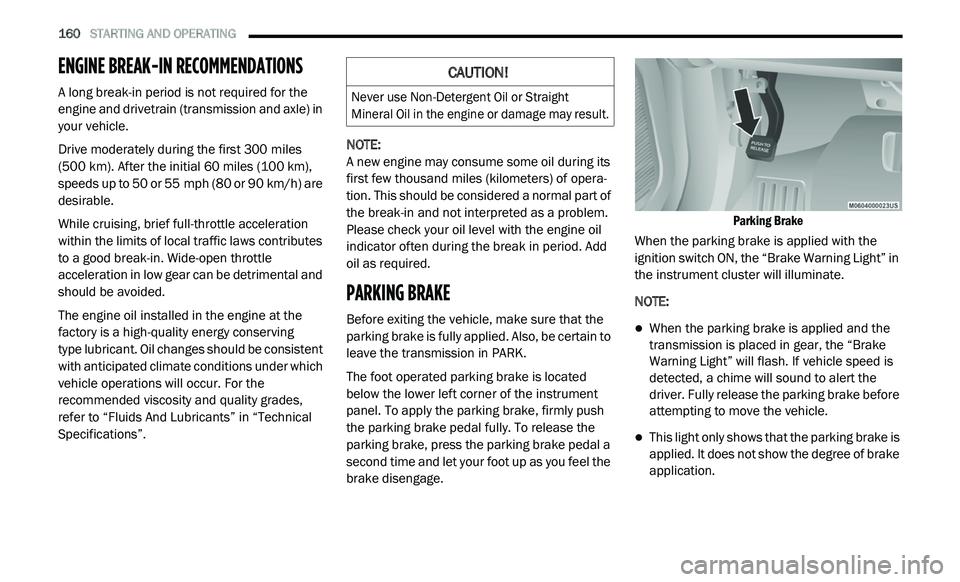
The foot operated parking brake is located
b e
low the lower left corner of the instrument
panel. To apply the parking brake, firmly push
the parking brake pedal fully. To release the
parking brake, press the parking brake pedal a
second time and let your foot up as you feel the
brake disengage.
Parking Brake
When the parking brake is applied with the
i g
nition switch ON, the “Brake Warning Light” in
the instrument cluster will illuminate.
NOTE:
When the parking brake is applied and the
transmission is placed in gear, the “Brake
Warning Light” will flash. If vehicle speed is
detected, a chime will sound to alert the
driver. Fully release the parking brake before
attempting to move the vehicle.
This light only shows that the parking brake is
applied. It does not show the degree of brake
application.
CAUTION!
Never use Non-Detergent Oil or Straight
Mineral Oil in the engine or damage may result.
Page 190 of 396
188 STARTING AND OPERATING
(Continued)
Shallow Standing Water
Although your vehicle is capable of driving
through shallow standing water, consider the
following Cautions and Warnings before doing
so.
WARNING!
Driving through standing water limits your
vehicle’s traction capabilities. Do not
exceed 5 mph (8 km/h) when driving
t h
rough standing water.
Driving through standing water limits your
vehicle’s braking capabilities, which
increases stopping distances. Therefore,
after driving through standing water, drive
slowly and lightly press on the brake pedal
several times to dry the brakes.
Failure to follow these warnings may result
in injuries that are serious or fatal to you,
your passengers, and others around you.
CAUTION!
Always check the depth of the standing
water before driving through it. Never drive
through standing water that is deeper than
the bottom of the tire rims mounted on the
vehicle.
Determine the condition of the road or the
path that is under water and if there are any
obstacles in the way before driving through
the standing water.
Do not exceed 5 mph (8 km/h) when
dr
iving through standing water. This will
minimize wave effects.
Driving through standing water may cause
damage to your vehicle’s drivetrain compo -
nents. Always inspect your vehicle’s fluids
( i
.e., engine oil, transmission, axle, etc.) for
signs of contamination (i.e., fluid that is
milky or foamy in appearance) after driving
through standing water. Do not continue to
operate the vehicle if any fluid appears
contaminated, as this may result in further
damage. Such damage is not covered by
the New Vehicle Limited Warranty.
Getting water inside your vehicle’s engine
can cause it to lock up and stall out, and
cause serious internal damage to the
engine. Such damage is not covered by the
New Vehicle Limited Warranty.
CAUTION! (Continued)
Page 218 of 396
216
SERVICING AND MAINTENANCE
SCHEDULED SERVICING
Your vehicle is equipped with an automatic
oil change indicator system. The oil change
i n
dicator system will remind you that it is time to
take your vehicle in for scheduled maintenance.
Based on engine operation conditions, the
oil change indicator message will illuminate.
This means that service is required for your
v e
hicle. Operating conditions such as frequent
short-trips, trailer tow, extremely hot or cold
ambient temperatures, and E-85 fuel usage will
influence when the “Change Oil” or “Oil Change
Required” message is displayed. Severe
operating conditions can cause the change oil
message to illuminate as early as 3,500 miles
(5,600 km) since last reset. Have your vehicle
s e
rviced as soon as possible, within the next
500 miles (805 km).
An authorized dealer will reset the oil change
i
n
dicator message after completing the
scheduled oil change. If a scheduled oil change
is performed by someone other than an
authorized dealer, the message can be reset
by referring to the steps described under
“ I
nstrument Cluster Display” in “Getting To
Know Your Instrument Panel” for further
information.
NOTE:
Under no circumstances should oil change
i n
tervals exceed 10,000 miles (16,000 km),
1 2
months or 350 hours of engine run time,
w h
ichever comes first. The 350 hours of engine
run or idle time is generally only a concern for
fleet customers.
Severe Duty All Models
Change engine oil at 4,000 miles (6,500 km) or
3 5
0 hours of engine run time if the vehicle is
operated in a dusty and off road environment or
is operated predominately at idle or only very
low engine RPM. This type of vehicle use is
considered Severe Duty. Once A Month Or Before A Long Trip:
Check engine oil level.
Check windshield washer fluid level.
Check tire pressure and look for unusual
wear or damage. Rotate tires at the first sign
of irregular wear, even if it occurs before the
oil indicator system turns on.
Check the fluid levels of the coolant reservoir,
brake master cylinder, power steering, and
transmission (4-speed only) and fill as
needed.
Check function of all interior and exterior
lights.
Page 234 of 396

232 SERVICING AND MAINTENANCE
(Continued)
BRAKE SYSTEM
In order to ensure brake system performance, all
brake system components should be inspected
periodically. Refer to the “Maintenance Plan” in
“Servicing and Maintenance” for the proper
maintenance intervals.
Master Cylinder — Brake Fluid Level Check
Check the fluid level in the master cylinder
immediately if the “Brake Warning Light”
indicates system failure.
Check the fluid level in the master cylinder
wh
en performing underhood services.
Clean the top of the master cylinder area before
r e
moving the cap. If necessary, add fluid to
bring the fluid level up to the requirements
described on the brake fluid reservoir. Overfilling of fluid is not recommended because
i
t
may cause leaking in the system.
Fluid level can be expected to fall as the brake
p a
ds wear. Brake fluid level should be checked
when pads are replaced. However, low fluid
level may be caused by a leak and a checkup
may be needed.
Use only manufacturer's recommended brake
fl
uid. Refer to “Fluids And Lubricants” in
“Technical Specifications” for further
information.WARNING!
Riding the brakes can lead to brake failure
and possibly a collision. Driving with your foot
resting or riding on the brake pedal can result
in abnormally high brake temperatures,
excessive lining wear, and possible brake
damage. You would not have your full braking
capacity in an emergency.
WARNING!
Use only manufacturer's recommended
brake fluid. Refer to “Fluids And Lubricants”
in “Technical Specifications” for further infor-
mation. Using the wrong type of brake fluid
c a
n severely damage your brake system
and/or impair its performance. The proper
type of brake fluid for your vehicle is also
identified on the original factory installed
hydraulic master cylinder reservoir.
To avoid contamination from foreign matter
or moisture, use only new brake fluid or
fluid that has been in a tightly closed
container. Keep the master cylinder reser -
voir cap secured at all times. Brake fluid in
a
open container absorbs moisture from
the air resulting in a lower boiling point.
This may cause it to boil unexpectedly
d u
ring hard or prolonged braking, resulting
in sudden brake failure. This could result in
a collision.
Overfilling the brake fluid reservoir can
result in spilling brake fluid on hot engine
parts, causing the brake fluid to catch fire.
Brake fluid can also damage painted and
vinyl surfaces, care should be taken to
avoid its contact with these surfaces.
Do not allow petroleum based fluid to
contaminate the brake fluid. Brake seal
components could be damaged, causing
partial or complete brake failure. This could
result in a collision.
WARNING! (Continued)
Page 247 of 396
SERVICING AND MAINTENANCE 245
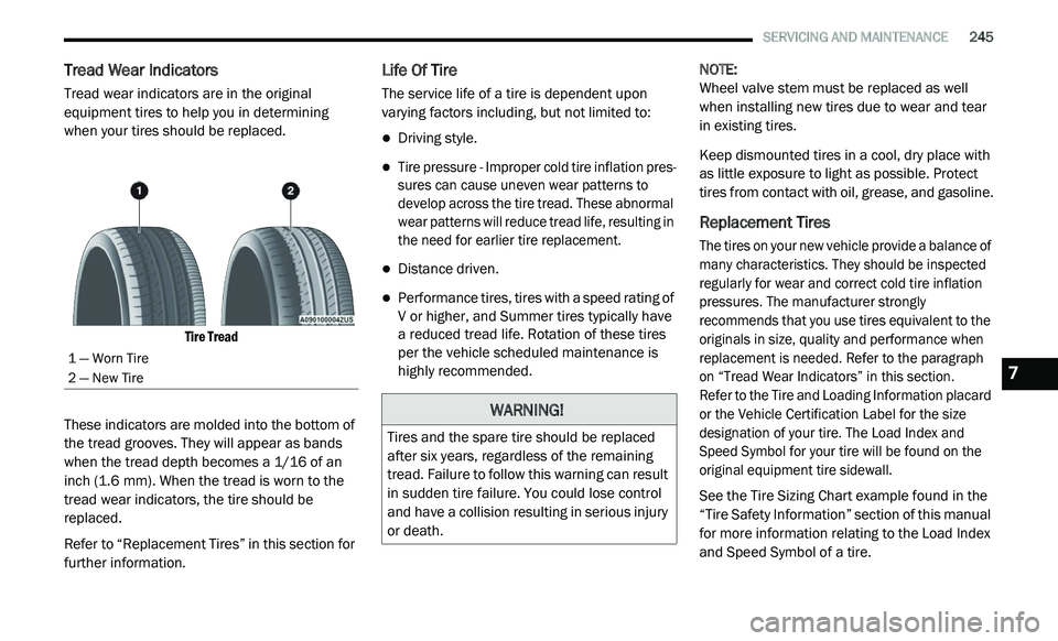
Tread Wear Indicators
Tread wear indicators are in the original
equipment tires to help you in determining
when your tires should be replaced.
Tire Tread
These indicators are molded into the bottom of
th
e tread grooves. They will appear as bands
when the tread depth becomes a 1/16 of an
inch (1.6 mm). When the tread is worn to the
t r
ead wear indicators, the tire should be
replaced.
Refer to “Replacement Tires” in this section for
f u
rther information.
Life Of Tire
The service life of a tire is dependent upon
varying factors including, but not limited to:
Driving style.
Tire pressure - Improper cold tire inflation pres -
sures can cause uneven wear patterns to
d e
velop across the tire tread. These abnormal
wear patterns will reduce tread life, resulting in
the need for earlier tire replacement.
Distance driven.
Performance tires, tires with a speed rating of
V or higher, and Summer tires typically have
a reduced tread life. Rotation of these tires
per the vehicle scheduled maintenance is
highly recommended. NOTE:
Wheel valve stem must be replaced as well
w h
en installing new tires due to wear and tear
in existing tires.
Keep dismounted tires in a cool, dry place with
a s
little exposure to light as possible. Protect
tires from contact with oil, grease, and gasoline.
Replacement Tires
The tires on your new vehicle provide a balance of
many characteristics. They should be inspected
regularly for wear and correct cold tire inflation
pressures. The manufacturer strongly
recommends that you use tires equivalent to the
originals in size, quality and performance when
replacement is needed. Refer to the paragraph
on “Tread Wear Indicators” in this section.
Refer to the Tire and Loading Information placard
o r
the Vehicle Certification Label for the size
designation of your tire. The Load Index and
Speed Symbol for your tire will be found on the
original equipment tire sidewall.
See the Tire Sizing Chart example found in the
“T
ire Safety Information” section of this manual
for more information relating to the Load Index
and Speed Symbol of a tire.
1 — Worn Tire
2 — New Tire
WARNING!
Tires and the spare tire should be replaced
after six years, regardless of the remaining
tread. Failure to follow this warning can result
in sudden tire failure. You could lose control
and have a collision resulting in serious injury
or death.
7