service indicator DODGE MAGNUM SRT 2007 1.G Owners Manual
[x] Cancel search | Manufacturer: DODGE, Model Year: 2007, Model line: MAGNUM SRT, Model: DODGE MAGNUM SRT 2007 1.GPages: 380, PDF Size: 6.63 MB
Page 15 of 380
consists of programming a blank key to the vehicle
electronics. A blank key is one, which has never been
programmed.
NOTE:When having the Sentry Key Immobilizer
System serviced, bring all vehicle keys with you to the
dealer.
Customer Key Programming
If you have two valid sentry keys, you can program new
sentry keys to the system by performing the following
procedure:
1. Cut the additional Sentry Key Transponder blank(s) to
match the ignition switch lock cylinder key code.
2. Insert the first valid key into the ignition switch and
turn the ignition switch ON for at least 3 seconds but no
longer than 15 seconds. Turn the ignition switch OFF and
remove the first key.
3. Insert the second valid key and turn the ignition
switch ON within 15 seconds. After ten seconds, a chime
will sound and the Vehicle Security Alarm Indicator
Light will begin to flash. Turn the ignition switch OFF
and remove the second key.4. Insert a blank Sentry Key into the ignition switch and
turn the ignition switch ON within 60 seconds. After 10
seconds, a single chime will sound and the Vehicle
Security Alarm Indicator Light will stop flashing, turn on
again for 3 seconds, and then turn off.
The new Sentry Key is programmed.The Keyless Entry
Transmitter will also be programmed during this pro-
cedure.
Repeat this procedure to program up to 8 keys. If you do
not have a programmed sentry key, contact your dealer
for details.
NOTE:If a programmed key is lost, see your dealer to
have all remaining keys erased from the systems
memory. This will prevent the lost key from starting your
vehicle. The remaining keys must then be repro-
grammed. All vehicle keys must be taken to the dealer at
the time of service to be reprogrammed.
14 THINGS TO KNOW BEFORE STARTING YOUR VEHICLE
Page 79 of 380
Working with Automated Systems
This method is designed to be used in instances where
one generally has to press numbers on the cellular phone
keypad while navigating through an automated tele-
phone system.
You can use your UConnectŸ system to access a voice-
mail system or an automated service, such as, paging
service or automated customer service. Some services
require immediate response selection, in some instances,
that may be too quick for use of UConnectŸ system.
When calling a number with your UConnectŸ system
that normally requires you to enter in a touch-tone
sequence on your cellular phone keypad, you can push
the 'Voice Recognition' button and say the sequence you
wish to enter followed by the word9Send.9For example,
if required to enter your pin number followed with a
pound3746#,youcanpressthe'Voice Recognition'
button and say93746#Send.9Saying a number, or
sequence of numbers, followed by9Send9is also to be
used to navigate through an automated customer service
center menu structure and to leave a number on a pager.
Barge In - Overriding Prompts
The 'Voice Recognition' button can be used when you
wish to skip part of a prompt and issue your voice
recognition command immediately. For example, if a
prompt is playing9Would you like to pair a phone, clear
a{,9you could press the 'Voice Recognition' button and
say9Pair a Phone9to select that option without having to
listen to the rest of the voice prompt.
Turning Confirmation Prompts On/Off
Turning confirmation prompts off will stop the system
from confirming your choices (e.g., the UConnectŸ
system will not repeat a phone number before you dial
it).
²Press the 'Phone' button to begin.
²After the9Ready9prompt and the following beep, say
9Setup Confirmations.9The UConnectŸ system will
play the current confirmation prompt status and you
will be given the choice to change it.
Phone and Network Status Indicators
If available on the radio and/or on a premium display
such as the instrument panel cluster, and supported by
78 UNDERSTANDING THE FEATURES OF YOUR VEHICLE
Page 136 of 380
INSTRUMENT CLUSTER DESCRIPTIONS
1. Fuel Gauge
The pointer shows the level of fuel in the fuel tank when
the ignition switch is in the ON position.
2. Trip Odometer Button
Press this button to change the display from odometer to
either of two trip odometer settings. The letter ªAº or ªBº
will appear when in the trip odometer mode. Push in and
hold the button for two seconds to reset the trip odometer
to 0 miles (kilometers). The odometer must be in trip
mode to reset it.
3. Speedometer
Indicates vehicle speed.
4. Electronic Speed Control Indicator Light
This light will turn on when the electronic
speed control is ON. (See page 103 for more
information.)5. Tachometer
The red segments indicate the maximum permissible
engine revolutions-per-minute (r.p.m. x 1000) for each
gear range. Ease up on the accelerator before reaching the
red area.
6. Voltage Light
This light monitors the electrical system volt-
age. The light should turn on momentarily as
the engine is started. If the light stays on or turns on
while driving, it indicates a problem with the charging
system. Immediate service should be obtained.
7. Electronic Throttle Control (ETC) Light
This light will turn on briefly as a bulb check
when the ignition switch is turned ON. This
light will also turn on while the engine is
running if there is a problem with the Elec-
tronic Throttle Control system.
If the light comes on while the engine is running, safely
bring the vehicle to a complete stop as soon as possible,
place the gear selector in park, and cycle the ignition key.
The light should turn off. If the light remains lit with the
UNDERSTANDING YOUR INSTRUMENT PANEL 135
4
Page 138 of 380
9. Turn Signal Indicators
The arrow will flash with the exterior turn signal
when the turn signal lever is operated.
NOTE:
A continuous chime will sound if the vehicle is
driven more than 1 mile (1.6 km) with either turn signal
on.
NOTE:Check for a defective outside light bulb if either
indicator flashes at a rapid rate. (See page 96 for more
information.)
10. Airbag Warning Light
This light will turn on for 6 to 8 seconds as a
bulb check when the ignition switch is first
turned ON. If the light is either not on
during starting, or stays on, or turns on
while driving, then have the system inspected at your
authorized dealer as soon as possible. (See page 47 for
more information.)11. Engine Temperature Warning Light
This light will turn on and a single chime will
sound to warn of an overheated engine condi-
tion. When this light turns on, the engine tem-
perature is critically hot. The vehicle should be turned
off immediately and serviced as soon as possible. (See
page 276 for more information.)
12. Electronic Stability Program (ESP)/Traction
Control System (TCS) Indicator Light
If this indicator light flashes during accelera-
tion, ease up on the accelerator and apply as
little throttle as possible. Adapt your speed
and driving to the prevailing road condi-
tions, and do not switch off the ESP. (See page 222 for
more information.)
13. Electronic Stability Program (ESP) / Brake
Assist System (BAS) Malfunction Indicator Light
The yellow ESP/BAS malfunction indicator
light will turn on when the key in the
ignition switch is turned to the ªONº posi-
tion. The light should go out with the engine
running. If the light remains on after several ignition
UNDERSTANDING YOUR INSTRUMENT PANEL 137
4
Page 140 of 380
Loose Fuel Filler Cap
If the vehicle diagnostic system determines that the fuel
filler cap is loose, improperly installed, or damaged, a
ªCheck Gascapº message will display in the Electronic
Vehicle Information Center (EVIC). Tighten the fuel filler
cap properly and press the odometer reset button to turn
off the message. If the problem continues, the message
will appear the next time the vehicle is started.
A loose, improperly installed, or damaged fuel filler cap
may also turn on the Malfunction Indicator Light (MIL).
(See page 292 for more information.)
20. Brake System Warning Light
This light monitors various brake functions,
including brake fluid level and parking
brake application. If the brake light turns on,
it may indicate that the parking brake is
applied, that the brake fluid level is low, or that there
is a problem with the anti-lock brake system.
The dual brake system provides a reserve braking capac-
ity to a portion of the hydraulic system in the event of a
failure. Failure of either half of the dual brake system isindicated by the Brake Warning Light, which will turn on
when the brake fluid level in the master cylinder drops
below a specified level.
The light will remain on until the cause is corrected.
NOTE:The light may flash momentarily during sharp
cornering maneuvers, which change fluid level condi-
tions. The vehicle should have service performed, and
the brake fluid level checked.
Immediate repair is necessary if brake failure is indicated.
WARNING!
Driving a vehicle with the brake light on is danger-
ous. Part of the brake system may have failed. It will
take longer to stop the vehicle. You could have an
accident. Have the vehicle checked immediately.
Vehicles equipped with Anti-Lock brakes (ABS) are also
equipped with Electronic Brake Force Distribution (EBD).
Both the Brake Warning Light and the ABS Light will
UNDERSTANDING YOUR INSTRUMENT PANEL 139
4
Page 143 of 380
23. Anti-Lock Brake Light
This light monitors the Anti-Lock Brake System.
The light will turn on when the ignition switch
is turned to the ON position and may stay on for as
long as four seconds.
If the ABS light remains on or turns on while driving,
then the Anti-Lock portion of the brake system is not
functioning and service is required. However, the con-
ventional brake system will continue to operate normally
if the BRAKE warning light is not on.
If the ABS light is on, the brake system should be serviced
as soon as possible to restore the benefits of Anti-Lock
brakes. If the ABS light does not turn on when the
Ignition switch is turned to the ON position, have the
light inspected by an authorized dealer. (See page 219 for
more information.)
24. Low Fuel Indicator Light
This light will turn on and a single chime will
sound when the fuel level drops to 1/8 tank. (See
page 257 for more information.)25. Malfunction Indicator Light
This light is part of an onboard diagnostic
system called OBD. The OBD system monitors
engine and automatic transmission control sys-
tems. The light will turn on when the key is in the ON
position before engine start. If the light does not come
on when turning the key from OFF to ON, have the
condition checked promptly.
Certain conditions such as a loose or missing gas cap,
poor fuel quality, etc. may illuminate the light after
engine start. The vehicle should be serviced if the light
stays on through several of your typical driving cycles. In
most situations, the vehicle will drive normally and will
not require towing.
The Malfunction Indicator Light flashes to alert you to
serious conditions that could lead to immediate loss of
power or severe catalytic converter damage. The vehicle
should be serviced as soon as possible if this occurs. (See
page 292 for more information.)
142 UNDERSTANDING YOUR INSTRUMENT PANEL
Page 215 of 380
Delayed Shifts in Cold Temperatures
During cold temperature operation, you may notice
delayed upshifts depending on engine and transmission
temperature as well as vehicle speed. This feature im-
proves warm up time of the engine and transmission to
achieve maximum efficiency.
Temporary Transmission Limp Home Mode
The transmission is monitored for abnormal conditions.
If a condition is detected that could result in transmission
damage, the transmission will engage Limp Home Mode.
If vehicle acceleration worsens, or the transmission no
longer shifts, the transmission is most likely operating in
the Limp Home Mode. In this mode, the transmission
will remain in the current gear until the vehicle is
brought to a stop. After the vehicle has stopped, P (Park),
R (Reverse), and N (Neutral) will continue to operate.
Second gear will operate in the D (Drive) shifter position.
The Malfunction Indicator Light may be illuminated.
A reset feature is available to allow the vehicle to be
driven to a dealer for service. To reset the transmission,
use the following procedure:
1. Stop the vehicle.2. Move the selector lever to the P (Park) position.
3. Turn off the engine.
4. Wait approximately 10 seconds.
5. Restart the engine.
6. Move the selector lever to the desired range. If the
problem is no longer detected, the transmission will
return to normal operation.
NOTE:Even if the transmission can be reset, we
recommend that you visit a dealer at your earliest
possible convenience. Your dealer has diagnostic equip-
ment to determine if the problem could recur.
Have the transmission checked at your authorized dealer
as soon as possible.
If the problem has been momentary, the transmission can
be reset to regain all forward gears.
Permanent Transmission Limp Home Mode
Permanent Limp Home Mode will be activated if the
transmission enters temporary Limp Home Mode three
214 STARTING AND OPERATING
Page 242 of 380
Tread Wear Indicators
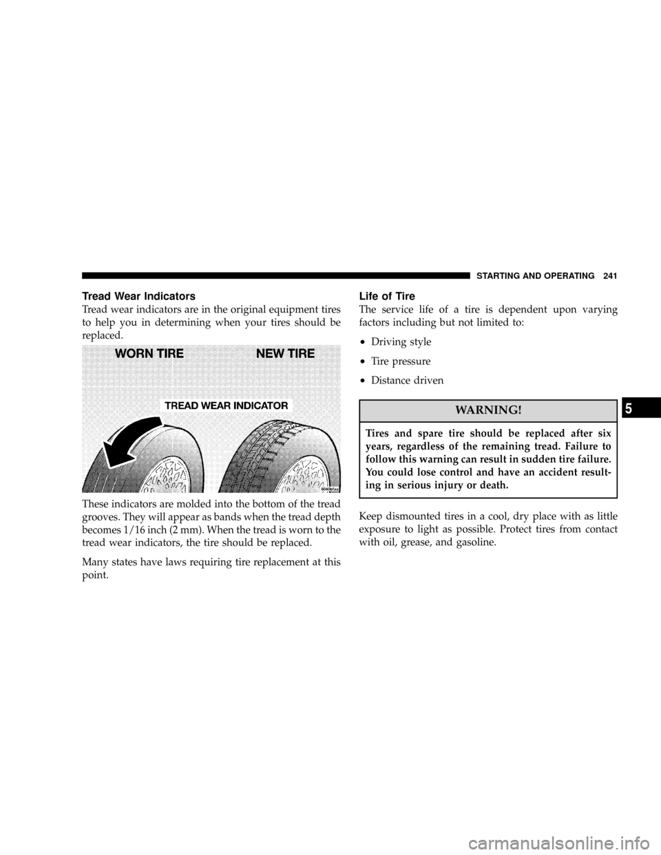
Tread wear indicators are in the original equipment tires
to help you in determining when your tires should be
replaced.
These indicators are molded into the bottom of the tread
grooves. They will appear as bands when the tread depth
becomes 1/16 inch (2 mm). When the tread is worn to the
tread wear indicators, the tire should be replaced.
Many states have laws requiring tire replacement at this
point.
Life of Tire
The service life of a tire is dependent upon varying
factors including but not limited to:
²Driving style
²Tire pressure
²Distance driven
WARNING!
Tires and spare tire should be replaced after six
years, regardless of the remaining tread. Failure to
follow this warning can result in sudden tire failure.
You could lose control and have an accident result-
ing in serious injury or death.
Keep dismounted tires in a cool, dry place with as little
exposure to light as possible. Protect tires from contact
with oil, grease, and gasoline.
STARTING AND OPERATING 241
5
Page 243 of 380
Replacement Tires
The tires on your new vehicle provide a balance of many
characteristics. They should be inspected regularly for
wear and correct cold tire inflation pressure. The manu-
facturer strongly recommends that you use tires equiva-
lent to the originals in size, quality and performance
when replacement is needed (refer to the paragraph on
ªTread Wear Indicatorsº). Refer to the ªTire and Loading
Informationº placard for the size designation of your tire.
The service description and load identification will be
found on the original equipment tire. Failure to use
equivalent replacement tires may adversely affect the
safety, handling, and ride of your vehicle. We recommend
that you contact your original equipment or an autho-
rized tire dealer with any questions you may have on tire
specifications or capability.WARNING!
²Do not use a tire, wheel size or rating other than
that specified for your vehicle. Some combina-
tions of unapproved tires and wheels may change
suspension dimensions and performance charac-
teristics, resulting in changes to steering, han-
dling, and braking of your vehicle. This can cause
unpredictable handling and stress to steering and
suspension components. You could lose control
and have an accident resulting in serious injury or
death. Use only the tire and wheel sizes with load
ratings approved for your vehicle.
²Never use a tire with a smaller load index or
capacity, other than what was originally equipped
on your vehicle. Using a tire with a smaller load
index could result in tire overloading and failure.
You could lose control and have an accident.
²Failure to equip your vehicle with tires having
adequate speed capability can result in sudden
tire failure and loss of vehicle control.
242 STARTING AND OPERATING
Page 293 of 380
ONBOARD DIAGNOSTIC SYSTEM Ð OBD II
Your vehicle is equipped with a sophisticated onboard
diagnostic system called OBD II. This system monitors
the performance of the emissions, engine, and automatic
transmission control systems. When these systems are
operating properly, your vehicle will provide excellent
performance and fuel economy, as well as engine emis-
sions well within current government regulations.
If any of these systems require service, the OBD II system
will turn on the ªMalfunction Indicator Light.º It will
also store diagnostic codes and other information to
assist your service technician in making repairs. Al-
though your vehicle will usually be drivable and not
need towing, see your dealer for service as soon as
possible.CAUTION!
Prolonged driving with the ªMalfunction Indicator
Lightº on could cause further damage to the emis-
sion control system. It could also affect fuel economy
and driveability. The vehicle must be serviced before
any emissions tests can be performed.
If the ªMalfunction Indicator Lightº is flashing
while the engine is running, severe catalytic con-
verter damage and power loss will soon occur. Im-
mediate service is required.
Loose Fuel Filler Cap
If the vehicle diagnostic system determines that the fuel
filler cap is loose, improperly installed, or damaged, a
ªCheck Gascapº message will display in the Electronic
Vehicle Information Center (EVIC) Ð if equipped. If this
occurs, tighten the fuel filler cap properly and press the
odometer reset button to turn off the message. If the
problem continues, the message will appear the next time
the vehicle is started.
292 MAINTAINING YOUR VEHICLE