relay DODGE NEON 1999 Service Owner's Manual
[x] Cancel search | Manufacturer: DODGE, Model Year: 1999, Model line: NEON, Model: DODGE NEON 1999Pages: 1200, PDF Size: 35.29 MB
Page 294 of 1200
HORNS
CONTENTS
page page
DESCRIPTION AND OPERATION
INTRODUCTION......................... 1
DIAGNOSIS AND TESTING
HORN RELAY........................... 2
HORN SWITCH.......................... 2
HORN................................. 1SYSTEM TEST.......................... 2
REMOVAL AND INSTALLATION
HORN RELAY........................... 4
HORN SWITCHES........................ 4
HORN................................. 4
DESCRIPTION AND OPERATION
INTRODUCTION
WARNING: ON VEHICLES EQUIPPED WITH AIR-
BAG, SEE GROUP 8M, RESTRAINT SYSTEMS FOR
STEERING WHEEL OR COLUMN REMOVAL PROCE-
DURES.
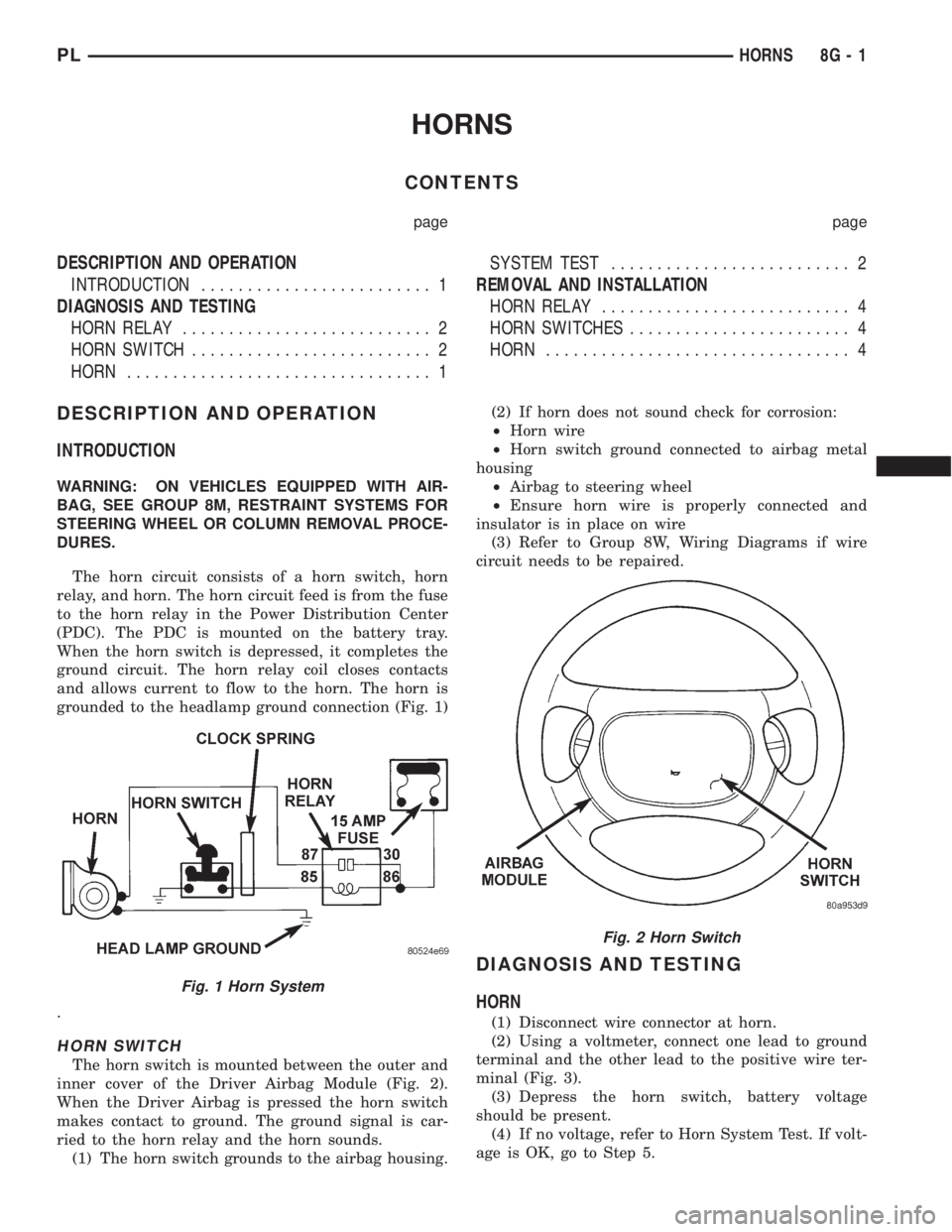
The horn circuit consists of a horn switch, horn
relay, and horn. The horn circuit feed is from the fuse
to the horn relay in the Power Distribution Center
(PDC). The PDC is mounted on the battery tray.
When the horn switch is depressed, it completes the
ground circuit. The horn relay coil closes contacts
and allows current to flow to the horn. The horn is
grounded to the headlamp ground connection (Fig. 1)
.
HORN SWITCH
The horn switch is mounted between the outer and
inner cover of the Driver Airbag Module (Fig. 2).
When the Driver Airbag is pressed the horn switch
makes contact to ground. The ground signal is car-
ried to the horn relay and the horn sounds.
(1) The horn switch grounds to the airbag housing.(2) If horn does not sound check for corrosion:
²Horn wire
²Horn switch ground connected to airbag metal
housing
²Airbag to steering wheel
²Ensure horn wire is properly connected and
insulator is in place on wire
(3) Refer to Group 8W, Wiring Diagrams if wire
circuit needs to be repaired.
DIAGNOSIS AND TESTING
HORN
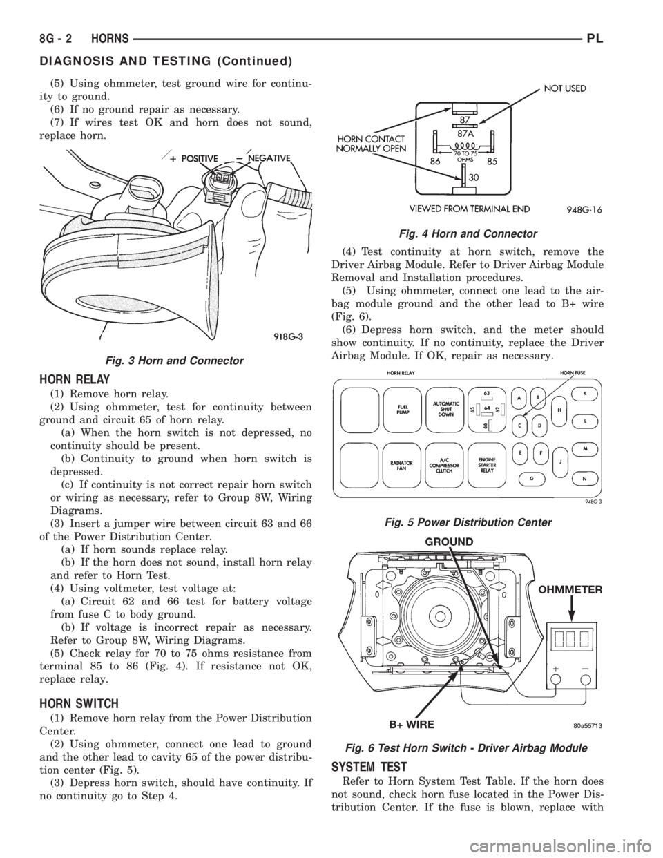
(1) Disconnect wire connector at horn.
(2) Using a voltmeter, connect one lead to ground
terminal and the other lead to the positive wire ter-
minal (Fig. 3).
(3) Depress the horn switch, battery voltage
should be present.
(4) If no voltage, refer to Horn System Test. If volt-
age is OK, go to Step 5.
Fig. 1 Horn System
Fig. 2 Horn Switch
PLHORNS 8G - 1
Page 295 of 1200
(5) Using ohmmeter, test ground wire for continu-
ity to ground.
(6) If no ground repair as necessary.
(7) If wires test OK and horn does not sound,
replace horn.
HORN RELAY
(1) Remove horn relay.
(2) Using ohmmeter, test for continuity between
ground and circuit 65 of horn relay.
(a) When the horn switch is not depressed, no
continuity should be present.
(b) Continuity to ground when horn switch is
depressed.
(c) If continuity is not correct repair horn switch
or wiring as necessary, refer to Group 8W, Wiring
Diagrams.
(3) Insert a jumper wire between circuit 63 and 66
of the Power Distribution Center.
(a) If horn sounds replace relay.
(b) If the horn does not sound, install horn relay
and refer to Horn Test.
(4) Using voltmeter, test voltage at:
(a) Circuit 62 and 66 test for battery voltage
from fuse C to body ground.
(b) If voltage is incorrect repair as necessary.
Refer to Group 8W, Wiring Diagrams.
(5) Check relay for 70 to 75 ohms resistance from
terminal 85 to 86 (Fig. 4). If resistance not OK,
replace relay.
HORN SWITCH
(1) Remove horn relay from the Power Distribution
Center.
(2) Using ohmmeter, connect one lead to ground
and the other lead to cavity 65 of the power distribu-
tion center (Fig. 5).
(3) Depress horn switch, should have continuity. If
no continuity go to Step 4.(4) Test continuity at horn switch, remove the
Driver Airbag Module. Refer to Driver Airbag Module
Removal and Installation procedures.
(5) Using ohmmeter, connect one lead to the air-
bag module ground and the other lead to B+ wire
(Fig. 6).
(6) Depress horn switch, and the meter should
show continuity. If no continuity, replace the Driver
Airbag Module. If OK, repair as necessary.
SYSTEM TEST
Refer to Horn System Test Table. If the horn does
not sound, check horn fuse located in the Power Dis-
tribution Center. If the fuse is blown, replace with
Fig. 3 Horn and Connector
Fig. 4 Horn and Connector
Fig. 5 Power Distribution Center
Fig. 6 Test Horn Switch - Driver Airbag Module
8G - 2 HORNSPL
DIAGNOSIS AND TESTING (Continued)
Page 296 of 1200
the correct fuse. If the horn fail to sound and the
new fuse blows when depressing the horn switch, a
short circuit in the horn or the horn wiring between
the fuse terminal and the horn is responsible, or a
defective horn switch allowed the horn to burn out is
responsible.
If the fuse is OK, test horn relay refer to Horn
Relay Test.
If the relay is OK, test horn refer to Horn Test.CAUTION: Continuous sounding of horn may
cause horn relay to fail.
Should the horn sound continuously:
²Unplug the horn relay from Power Distribution
Center.
²Refer to Horn Relay Test.
Refer to Group 8W, wiring Disgrams for circuit and
wiring information.
HORN SYSTEM TEST
CONDITION POSSIBLE CAUSE CORRECTION
Horn sounds continuously.
NOTE: Immediately unplug
horn relay in the Power
Distribution Center (PDC)(1) Faulty horn relay.
(2) Horn control circuit to relay
shorted to ground.
(3) Pinched horn switch wire under
Driver Airbag Module.
(4) Defective horn switch(1) Refer to horn relay test.
(2) Check terminal 65 in PDC for
continuity to ground. If continuity to ground
indicates:
(a) Steering Wheel horn switch/lead
shorted to ground.
(b) Wiring harness shorted to ground. Find
the short and repair as necessary.
(3) Replace Driver Airbag Module.
(4) Replace Driver Airbag Module.
Horn sound intermittently as
the steering wheel is turned.(1) Horn relay control circuit X3 is
shorted to ground inside steering
wheel.
(2) Pinched horn switch wire under
Driver Airbag Module
(3) Defective horn switch(1) Remove Driver Airbag Module and/or
steering wheel. Check for rubbing or loose
wire/connector, repair as necessary.
(2) Replace Driver Airbag Module.
(3) Replace Driver Airbag Module.
Horn does not sound (1) Check fuse 23 in PDC
(2) No Voltage at horn RELAY
TERMINALS 62 & 66, and fuse is
OK.
(3) Open circuit from terminal 65 of
the horn relay to horn switch X3
circuit.
(4) Defective or damaged horn.
(5) Defective horn switch(1) Replace fuse if blown repair as
necessary.
(2) No voltage, repair PDC as necessary.
(3) Repair circuit as necessary.
(4) Voltage at horn when horn switch is
pressed, replace horn.
(5) Replace Driver Airbag Module.
Fuse blows when horn
sounds(1) Short circuit in horn or horn
wiring(1) Remove horn relay, check for shorted
horn or horn wiring. Disconnect horn wire
harness to isolate short and repair as
necessary.
Fuse blows without blowing
horn(1) Short circuit (1) Remove relay, install new fuse, if fuse
does not blow replace horn relay. If fuse
blows with relay removed, check for short
to ground with ohmmeter on circuit
between terminals 62 & 66 and the fuse
terminal. Repair as necessary.
NOTE: For wiring repairs
refer to Group 8W, Wire
Diagrams.
PLHORNS 8G - 3
DIAGNOSIS AND TESTING (Continued)
Page 297 of 1200
REMOVAL AND INSTALLATION
HORN
REMOVAL
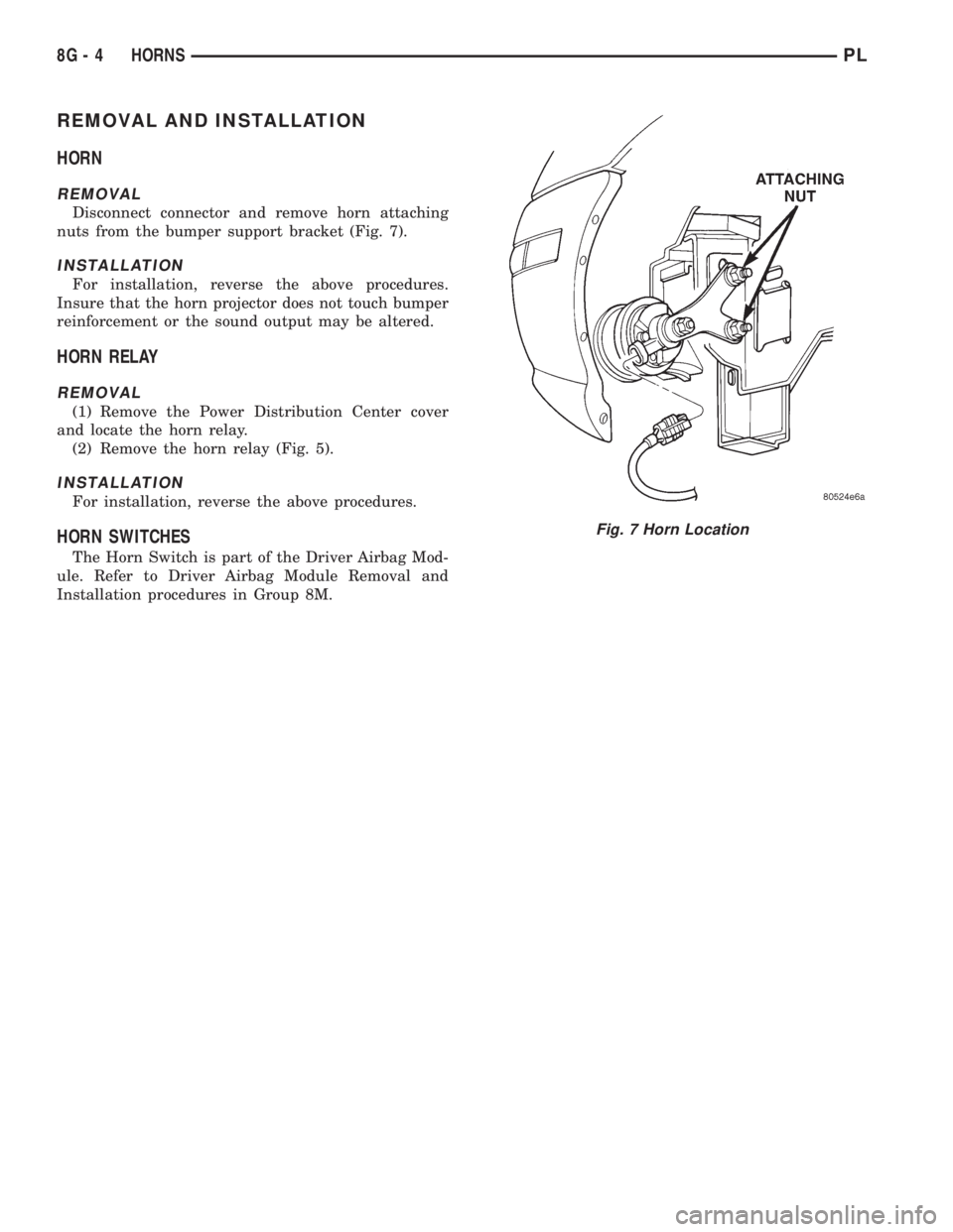
Disconnect connector and remove horn attaching
nuts from the bumper support bracket (Fig. 7).
INSTALLATION
For installation, reverse the above procedures.
Insure that the horn projector does not touch bumper
reinforcement or the sound output may be altered.
HORN RELAY
REMOVAL
(1) Remove the Power Distribution Center cover
and locate the horn relay.
(2) Remove the horn relay (Fig. 5).
INSTALLATION
For installation, reverse the above procedures.
HORN SWITCHES
The Horn Switch is part of the Driver Airbag Mod-
ule. Refer to Driver Airbag Module Removal and
Installation procedures in Group 8M.
Fig. 7 Horn Location
8G - 4 HORNSPL
Page 301 of 1200
CHECKING FOR DIAGNOSTIC CODES
When trying to verify a speed control system elec-
tronic malfunction: Connect a DRB scan tool if avail-
able to the data link connector. The connector is
located at left side of the steering column, and at
lower edge of the panel.
(1) A speed control malfunction may occur without
a diagnostic code being indicated.
Refer to Group 25, for further information and use-
age of the DRB scan tool and a more complete list of
Diagnostic Trouble Code.
SPEED CONTROL SLOWS DOWN BY ITSELF
Test vehicle speed sensor, refer to group 8E. If sen-
sor fails replace sensor, if it passes perform the fol-
lowing test:
(1) Perform the speed control switch test on the
DECEL switch, if it fails replace switch.
(2) If the switch passes, conduct the vacuum sup-
ply test.
(3) If it passes, conduct the servo vacuum test. If it
fails replace servo.
(4) If continuity, replace the PCM.
SPEED CONTROL ELECTRICAL TEST
Electronic speed control systems may be tested
using two different methods. One involves use of aDRB. If this test method is desired, refer to the Pow-
ertrain Diagnostic Test Procedures for charging and
speed control system manual.
The other test method uses a volt/ohm meter. The
volt/ohm meter method is described in the following
tests.
If any information is needed concerning wiring,
refer to Group 8W, Wiring Diagrams (Fig. 4).
CAUTION: When test probing for voltage or conti-
nuity at electrical connectors, care must be taken
not to damage connector, terminals, or seals. If
these components are damaged, intermittent or
complete system failure may occur.
When electrical connections are removed, corrosion
should be removed from electrical terminals and a
light coating of Mopar Multi-Purpose Grease, or
equivalent, applied. Inspect connectors for damage
terminals.
A poor connection can cause a complete or inter-
mittent malfunction and is also the only connection
in the circuit, that can not be tested. For this reason,
a loose connection may be misdiagnosed as a compo-
nent malfunction.
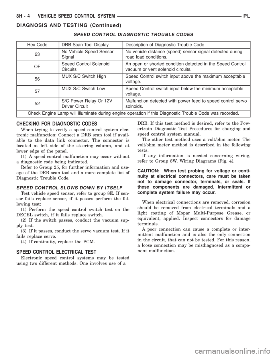
SPEED CONTROL DIAGNOSTIC TROUBLE CODES
Hex Code DRB Scan Tool Display Description of Diagnostic Trouble Code
23No Vehicle Speed Sensor
SignalNo vehicle distance (speed) sensor signal detected during
road load conditions.
OFSpeed Control Solenoid
CircuitsAn open or shorted condition detected in the Speed Control
vacuum or vent solenoid circuits.
56MUX S/C Switch High Speed Control switch input above the maximum acceptable
voltage.
57MUX S/C Switch Low Speed Control switch input below the minimum acceptable
voltage.
52S/C Power Relay Or 12V
Driver CircuitMalfunction detected with power feed to speed control servo
solnoids.
Check Engine Lamp will illuminate during engine operation if this Diagnostic Trouble Code was recorded.
8H - 4 VEHICLE SPEED CONTROL SYSTEMPL
DIAGNOSIS AND TESTING (Continued)
Page 314 of 1200
WINDSHIELD WIPERS AND WASHERS
CONTENTS
page page
WINDSHIELD WASHER SYSTEM............. 8WINDSHIELD WIPERS..................... 1
WINDSHIELD WIPERS
INDEX
page page
GENERAL INFORMATION
INTRODUCTION......................... 1
DESCRIPTION AND OPERATION
WIPER BLADES.......................... 1
DIAGNOSIS AND TESTING
WINDSHIELD WIPER CONDITION............ 2
WIPER MOTOR.......................... 3
WIPER SWITCH.......................... 5
REMOVAL AND INSTALLATION
WIPER ARM............................. 5WIPER BLADE ELEMENT.................. 5
WIPER BLADE........................... 5
WIPER LINKAGE......................... 6
WIPER MODULE......................... 6
WIPER MOTOR.......................... 6
WIPER SWITCH.......................... 6
CLEANING AND INSPECTION
WIPER BLADES.......................... 6
ADJUSTMENTS
WIPER ARM ADJUSTMENT................. 7
GENERAL INFORMATION
INTRODUCTION
WARNING: VEHICLES ARE EQUIPPED WITH AN
AIRBAG, REFER TO GROUP 8M, RESTRAINT SYS-
TEMS FOR STEERING WHEEL OR COLUMN SER-
VICE PROCEDURES.
The windshield wipers will only operate with the
ignition switch in the ACCESSORY or IGNITION
RUN position. The wiper circuit is protect against
over loads by a fuse in the fuse block and a circuit
breaker within the wiper motor. This protects the cir-
cuitry of the wiper system and the vehicle.
The wiper motor has permanent magnet fields.
The intermittent wiper system, in addition to low
and high speed, has a delay mode and a pulse wipe
mode. The delay mode has a range of 1 to 15 seconds.
Pulse wipe is accomplished by momentarily moving
the stalk lever into the WASH position while the
wiper switch is in either OFF or DELAY position.
The wiper blades then sweep once or twice and
return to the previous wiper switch mode, OFF or
DELAY.The intermittent wiper function is integral to the
wiper switch. All electronics and relay are inside the
switch assembly.
The wiper system completes the wipe cycle when
the switch is turned OFF. The blades park in the
lowest portion of the wipe pattern.
DESCRIPTION AND OPERATION
WIPER BLADES
Wiper blades, exposed to the weather for a long
period of time, tend to lose their wiping effectiveness.
Periodic cleaning of the wiper blade is suggested to
remove the accumulation of salt and road film. The
wiper blades, arms, and windshield should be
cleaned with a sponge or cloth and a mild detergent
or nonabrasive cleaner. If the blades continue to
streak or smear, they should be replaced. The right
and left wipers are different blade lengths. The
driver side length is 525 mm and the passenger side
length is 450 mm. The blades should not be inter-
changed.
PLWINDSHIELD WIPERS AND WASHERS 8K - 1
Page 315 of 1200
DIAGNOSIS AND TESTING
WINDSHIELD WIPER CONDITION
WARNING: ON VEHICLES EQUIPPED WITH AIR-
BAGS, SEE GROUP 8M, RESTRAINT SYSTEMS FOR
STEERING WHEEL OR COLUMN REMOVAL PROCE-
DURES.
The following is a list of general wiper motor sys-
tem problems, the tests that are to be performed to
locate the faulty part, and the corrective action to be
taken.
Whatever the problem, disconnect motor wire har-
ness and clean the terminals, then connect motor
wire harness and test.
MOTOR WILL NOT OPERATE IN SOME OR ALL
SWITCH POSITIONS
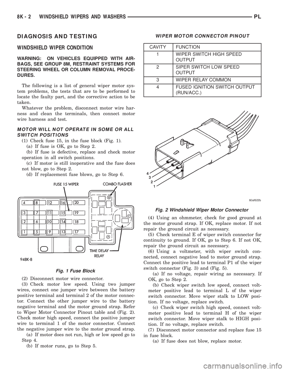
(1) Check fuse 15, in the fuse block (Fig. 1).
(a) If fuse is OK, go to Step 2.
(b) If fuse is defective, replace and check motor
operation in all switch positions.
(c) If motor is still inoperative and the fuse does
not blow, go to Step 2.
(d) If replacement fuse blows, go to Step 6.
(2) Disconnect motor wire connector.
(3) Check motor low speed. Using two jumper
wires, connect one jumper wire between the battery
positive terminal and terminal 2 of the motor connec-
tor. Connect the other jumper wire to the battery
negative terminal and the motor ground strap. Refer
to Wiper Motor Connector Pinout table and (Fig. 2).
Check motor high speed, connect the positive jumper
wire to terminal 1 of the motor connector. Connect
the negative jumper wire to the motor ground strap.
(a) If motor does not run, high or low speed go to
Step 4.
(b) If motor runs, go to Step 5.(4) Using an ohmmeter, check for good ground at
the motor ground strap. If OK, replace motor. If not
repair the ground circuit as necessary.
(5) Check terminal E of wiper switch connector for
continuity to ground. If OK, go to Step 6. If not OK,
repair the ground circuit as necessary.
(6) Using a voltmeter, with wiper switch con-
nected, connect negative lead to motor ground strap.
Connect the positive lead to terminal P1 of the wiper
switch connector (Fig. 3) and (Fig. 5).
(a) If no voltage, repair wiring as necessary. If
OK, go to Step 2.
(b) Check wiper switch low speed, connect volt-
meter positive lead to terminal L of the wiper
switch connector. Move wiper stalk to LOW posi-
tion. If no voltage, replace switch.
(c) Check wiper switch high speed, connect volt-
meter positive lead to terminal H of the wiper
switch connector. Move wiper stalk to HIGH posi-
tion. If no voltage, replace switch.
(7) Disconnect motor connector and replace fuse 15
in fuse block.
(a) If fuse does not blow, replace motor.
Fig. 1 Fuse Block
WIPER MOTOR CONNECTOR PINOUT
CAVITY FUNCTION
1 WIPER SWITCH HIGH SPEED
OUTPUT
2 SIPER SWITCH LOW SPEED
OUTPUT
3 WIPER RELAY COMMON
4 FUSED IGNITION SWITCH OUTPUT
(RUN/ACC.)
Fig. 2 Windshield Wiper Motor Connector
8K - 2 WINDSHIELD WIPERS AND WASHERSPL
Page 324 of 1200
WINDSHIELD WIPERS AND WASHERS
CONTENTS
page
WINDSHIELD WIPERS.................... 1
WINDSHIELD WIPERS
INDEX
page page
GENERAL INFORMATION
INTRODUCTION........................ 1
DIAGNOSIS AND TESTING
WINDSHIELD WIPER CONDITION........... 1WIPER MOTOR......................... 3
WIPER SWITCH......................... 5
GENERAL INFORMATION
INTRODUCTION
WARNING: VEHICLES ARE EQUIPPED WITH AN
AIRBAG, REFER TO GROUP 8M, RESTRAINT SYS-
TEMS FOR STEERING WHEEL OR COLUMN SER-
VICE PROCEDURES.
The windshield wipers will only operate with the
ignition switch in the ACCESSORY or IGNITION
RUN position. The wiper circuit is protect against
over loads by a fuse in the fuse block and a circuit
breaker within the wiper motor. This protects the cir-
cuitry of the wiper system and the vehicle.
The wiper motor has permanent magnet fields.
The intermittent wiper system, in addition to low
and high speed, has a delay mode and a pulse wipe
mode. The delay mode has a range of 1 to 15 seconds.
Pulse wipe is accomplished by momentarily moving
the stalk lever into the WASH position while the
wiper switch is in either OFF or DELAY position.
The wiper blades then sweep once or twice and
return to the previous wiper switch mode, OFF or
DELAY.
The intermittent wiper function is integral to the
wiper switch. All electronics and relay are inside the
switch assembly.
The wiper system completes the wipe cycle when
the switch is turned OFF. The blades park in the
lowest portion of the wipe pattern.
DIAGNOSIS AND TESTING
WINDSHIELD WIPER CONDITION
WARNING: ON VEHICLES EQUIPPED WITH AIR-
BAGS, SEE GROUP 8M, RESTRAINT SYSTEMS FOR
STEERING WHEEL OR COLUMN REMOVAL PROCE-
DURES.
The following is a list of general wiper motor sys-
tem problems, the tests that are to be performed to
locate the faulty part, and the corrective action to be
taken.
Whatever the problem, disconnect motor wire har-
ness and clean the terminals, then connect motor
wire harness and test.
MOTOR WILL NOT OPERATE IN SOME OR ALL
SWITCH POSITIONS
(1) Check fuse 15, in the fuse block (Fig. 1).
(a) If fuse is OK, go to Step 2.
(b) If fuse is defective, replace and check motor
operation in all switch positions.
(c) If motor is still inoperative and the fuse does
not blow, go to Step 2.
(d) If replacement fuse blows, go to Step 6.
PLWINDSHIELD WIPERS AND WASHERS 8K - 1
Page 330 of 1200
LAMPS
CONTENTS
page page
BULB APPLICATION...................... 13
HEADLAMP ALIGNMENT................... 4
LAMP BULB SERVICE..................... 6LAMP DIAGNOSIS........................ 1
LAMP SERVICE........................... 9
LAMP SYSTEMS......................... 12
LAMP DIAGNOSIS
INDEX
page page
GENERAL INFORMATION
DAYTIME RUNNING LAMP MODULE.......... 1
GENERAL INFORMATION.................. 1
SAFETY PRECAUTIONS................... 1DIAGNOSIS AND TESTING
DIAGNOSTIC PROCEDURES................ 1
FOG LAMP.............................. 3
HEADLAMP DIAGNOSIS................... 2
GENERAL INFORMATION
GENERAL INFORMATION
Each vehicle is equipped with various lamp assem-
blies. A good ground is necessary for proper lighting
operation. Grounding is provided by the lamp socket
when it comes in contact with the metal body, or
through a separate ground wire.
When changing lamp bulbs check the socket for
corrosion. If corrosion is present, clean it with a wire
brush and coat the inside of the socket lightly with
Mopar Multi-Purpose Grease or equivalent.
SAFETY PRECAUTIONS
WARNING: EYE PROTECTION SHOULD BE USED
WHEN SERVICING GLASS COMPONENTS. PER-
SONAL INJURY CAN RESULT.
CAUTION: Do not touch the glass of halogen bulbs
with fingers or other possibly oily surface, reduced
bulb life will result.
Do not use bulbs with higher candle power than
indicated in the Bulb Application table at the end of
this group. Damage to lamp and/or Daytime Run-
ning Lamp Module can result.
Do not use fuses, circuit breakers or relays hav-
ing greater amperage value than indicated on the
fuse panel or in the Owners Manual.When it is necessary to remove components to ser-
vice another, it should not be necessary to apply
excessive force or bend a component to remove it.
Before damaging a trim component, verify hidden
fasteners or captured edges are not holding the com-
ponent in place.
DAYTIME RUNNING LAMP MODULE
PL vehicles built for use in Canada are equipped
with a Daytime Running Lamp (DRL) system. The
DRL system operates the headlamps at 50% illumi-
nation with the headlamp switch OFF, park brake
released and the ignition ON. The DRL system is
controlled by the Daytime Running Lamp Module.
The DRL module overrides the headlamp switch
when the headlamps are turned OFF. The headlamps
operate normally when the headlamps are turned
ON.
DIAGNOSIS AND TESTING
DIAGNOSTIC PROCEDURES
When a vehicle experiences problems with the
headlamp system, verify the condition of the battery
connections, charging system, headlamp bulbs, wire
connectors, relay, high beam dimmer switch and
headlamp switch. Refer to Group 8W, Wiring Dia-
grams for component locations and circuit informa-
tion.
PLLAMPS 8L - 1
Page 364 of 1200
ELECTRICALLY HEATED SYSTEMS
CONTENTS
page page
DESCRIPTION AND OPERATION
INTRODUCTION......................... 1
REAR WINDOW DEFOGGER SWITCH........ 1
DIAGNOSIS AND TESTING
DEFOGGER SYSTEM..................... 1GRID LINES............................ 2
REAR WINDOW DEFOGGER SWITCH........ 2
SERVICE PROCEDURES
GRID LINE AND TERMINAL REPAIR......... 3
DESCRIPTION AND OPERATION
INTRODUCTION
For proper operation of the Rear Window Defogger
system refer to the Owner's Manual.
The system consists of a rear glass with two verti-
cal bus bars and a series of electrically connected
grid lines fired on the inside surface. A control switch
and a timer relay combined into a single assembly is
used on all models (Fig. 1).
Circuit protection is provided by a maxi fuse,
located in the Power Distribution Center, for the
heated grid circuit and by a fuse for the relay control
circuit.
When the switch is turned to the ON position, cur-
rent is directed to the rear defogger grid lines. The
heated grid lines heat the rear glass to clear the sur-
face of fog or frost.
CAUTION: Grid lines can be damaged or scraped
off with sharp instruments, care should be taken in
cleaning glass or removing foreign materials,
decals or stickers. Normal glass cleaning solvents
or hot water used with rags or toweling is recom-
mended.
REAR WINDOW DEFOGGER SWITCH
The rear window defogger switch is a control
switch and timer relay integrated into a single panel
mounted assembly. Actuating the switch energizes
the circuit which allows current to flow through the
grid lines. Upon initial actuation for approximately
eight to ten minutes, or until either the switch or
ignition is turned off. An indicating lamp illuminates
a lens inlaid in the control switch.
DIAGNOSIS AND TESTING
DEFOGGER SYSTEM
Electrically heated rear window defogger operation
can be checked in vehicle in the following manner:
(1) Turn ignition switch to the ON position.
(2) Connect an ammeter in series with the battery.
Push the defogger control switch to the ON position.
A distinct increase in amperage draw should be
noted.
(3) The rear window defogger operation can be
checked by feeling the glass. A distinct difference in
temperature between the grid lines and adjacent
clear glass can be detected in three to four minutes
of operation.
(4) Using a DC voltmeter, connect negative lead to
Point B, and the positive lead to Point A (Fig. 2). The
voltmeter should read 10-14 volts.
(5) Step 2, Step 3 or Step 4 above will confirm
system operation. Indicator light illumination means
that there is power available at the output of the
relay only, and does not necessarily verify system
operation.
Fig. 1 Rear Window Defogger
PLELECTRICALLY HEATED SYSTEMS 8N - 1