relay DODGE NEON 1999 Service Owner's Guide
[x] Cancel search | Manufacturer: DODGE, Model Year: 1999, Model line: NEON, Model: DODGE NEON 1999Pages: 1200, PDF Size: 35.29 MB
Page 365 of 1200
(6) If turning the switch ON produced no distinct
current draw on the ammeter the problem should be
isolated in the following manner:
(a) Confirm the ignition switch is ON.
(b) Ensure that the heated rear glass feed wire
is connected to the terminal or pigtail and that the
ground wire is in fact grounded.
(c) Ensure that the maxi-fuse and control circuit
fuse are OK and all electrical connections are
secure.
(7) When the above steps have been completed and
the system is still inoperative, one or more of the fol-
lowing is defective:
(a) Control switch/timer relay module.
(b) All rear window grid lines would have to be
broken or one of the feed wires are not connected
for the system to be inoperative.
(8) If turning the switch ON produces severe volt-
meter deflection, the circuit should be closely checked
for a shorting condition.
(9) If the system operation has been verified but
indicator lamp does not light, replace the switch.
(10) For detailed wiring information, refer to group
8W, Wiring Diagrams.
GRID LINES
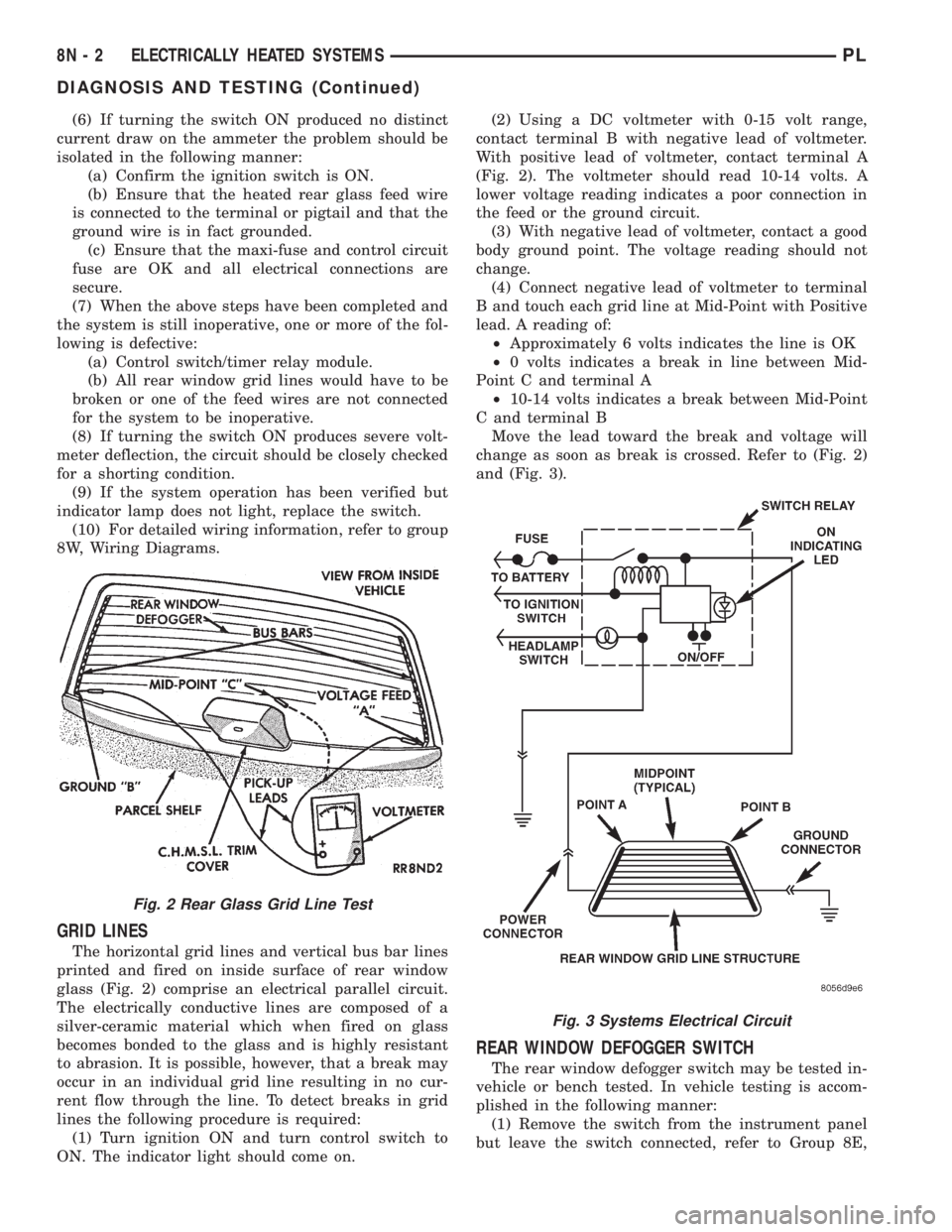
The horizontal grid lines and vertical bus bar lines
printed and fired on inside surface of rear window
glass (Fig. 2) comprise an electrical parallel circuit.
The electrically conductive lines are composed of a
silver-ceramic material which when fired on glass
becomes bonded to the glass and is highly resistant
to abrasion. It is possible, however, that a break may
occur in an individual grid line resulting in no cur-
rent flow through the line. To detect breaks in grid
lines the following procedure is required:
(1) Turn ignition ON and turn control switch to
ON. The indicator light should come on.(2) Using a DC voltmeter with 0-15 volt range,
contact terminal B with negative lead of voltmeter.
With positive lead of voltmeter, contact terminal A
(Fig. 2). The voltmeter should read 10-14 volts. A
lower voltage reading indicates a poor connection in
the feed or the ground circuit.
(3) With negative lead of voltmeter, contact a good
body ground point. The voltage reading should not
change.
(4) Connect negative lead of voltmeter to terminal
B and touch each grid line at Mid-Point with Positive
lead. A reading of:
²Approximately 6 volts indicates the line is OK
²0 volts indicates a break in line between Mid-
Point C and terminal A
²10-14 volts indicates a break between Mid-Point
C and terminal B
Move the lead toward the break and voltage will
change as soon as break is crossed. Refer to (Fig. 2)
and (Fig. 3).
REAR WINDOW DEFOGGER SWITCH
The rear window defogger switch may be tested in-
vehicle or bench tested. In vehicle testing is accom-
plished in the following manner:
(1) Remove the switch from the instrument panel
but leave the switch connected, refer to Group 8E,
Fig. 2 Rear Glass Grid Line Test
Fig. 3 Systems Electrical Circuit
8N - 2 ELECTRICALLY HEATED SYSTEMSPL
DIAGNOSIS AND TESTING (Continued)
Page 366 of 1200
Instrument Panel and Systems for removal proce-
dures.
(2) Turn the ignition switch ON.
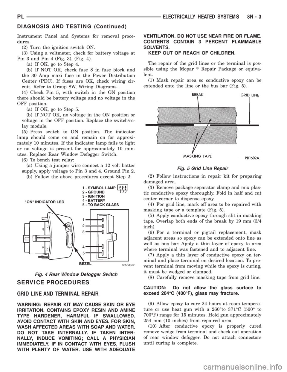
(3) Using a voltmeter, check for battery voltage at
Pin 3 and Pin 4 (Fig. 3), (Fig. 4).
(a) If OK, go to Step 4.
(b) If NOT OK, check fuse 8 in fuse block and
the 30 Amp maxi fuse in the Power Distribution
Center (PDC). If fuses are OK, check wiring cir-
cuit. Refer to Group 8W, Wiring Diagrams.
(4) Check Pin 5, with switch in the ON position
there should be battery voltage and no voltage in the
OFF position.
(a) If OK, go to Step 5.
(b) If NOT OK, no voltage in the ON position or
voltage in the OFF position. Replace the switch/re-
lay module.
(5) Press switch to ON position. The indicator
lamp should come on and remain on for approxi-
mately 10 minutes. If the indicator lamp fails to light
or no voltage is present for approximately 10 min-
utes. Replace Rear Window Defogger Switch.
(6) To bench test relay:
(a) Using a jumper wire connect a 12 volt batter
supply, apply voltage to Pin 3 and 4. Ground Pin 2.
(b) Follow the above procedures except Step 2
SERVICE PROCEDURES
GRID LINE AND TERMINAL REPAIR
WARNING: REPAIR KIT MAY CAUSE SKIN OR EYE
IRRITATION. CONTAINS EPOXY RESIN AND AMINE
TYPE HARDENER, HARMFUL IF SWALLOWED.
AVOID CONTACT WITH SKIN AND EYES. FOR SKIN,
WASH AFFECTED AREAS WITH SOAP AND WATER.
DO NOT TAKE INTERNALLY. IF TAKEN INTER-
NALLY, INDUCE VOMITING; CALL A PHYSICIAN
IMMEDIATELY. IF IN CONTACT WITH EYES, FLUSH
WITH PLENTY OF WATER. USE WITH ADEQUATEVENTILATION. DO NOT USE NEAR FIRE OR FLAME.
CONTENTS CONTAIN 3 PERCENT FLAMMABLE
SOLVENTS.
KEEP OUT OF REACH OF CHILDREN.
The repair of the grid lines or the terminal is pos-
sible using the MopartRepair Package or equiva-
lent.
(1) Mask repair area so conductive epoxy can be
extended onto the line or the bus bar (Fig. 5).
(2) Follow instructions in repair kit for preparing
damaged area.
(3) Remove package separator clamp and mix plas-
tic conductive epoxy thoroughly. Fold in half and cut
center corner to dispense epoxy.
(4) For grid line, mark off area to be repaired with
masking tape or a template (Fig. 5).
(5) Apply conductive epoxy through slit in masking
tape. Overlap both ends of the break by 19 mm (3/4
inch).
(6) For a terminal or pigtail replacement, mask
adjacent areas so epoxy can be extended onto line as
well as bus bar. Apply a thin layer of epoxy to area
where terminal was fastened and to adjacent line.
(7) Apply a thin layer of conductive epoxy on ter-
minal and place terminal on desired location. To pre-
vent terminal from moving while the epoxy is curing,
it must be wedged or clamped.
(8) Carefully remove masking tape from grid line.
CAUTION: Do not allow the glass surface to
exceed 204ÉC (400ÉF), glass may fracture.
(9) Allow epoxy to cure 24 hours at room tempera-
ture or use heat gun with a 260Éto 371ÉC (500É to
700ÉF) range for 15 minutes. Hold gun approximately
254 mm (10 inches) from repaired area.
(10) After conductive epoxy is properly cured
remove wedge from terminal and check out operation
of rear window defogger. Do not attach connectors
until curing is complete.
Fig. 4 Rear Window Defogger Switch
Fig. 5 Grid Line Repair
PLELECTRICALLY HEATED SYSTEMS 8N - 3
DIAGNOSIS AND TESTING (Continued)
Page 368 of 1200
ELECTRICALLY HEATED SYSTEMS
CONTENTS
page page
DIAGNOSIS AND TESTING
REAR WINDOW DEFOGGER SWITCH....... 1REMOVAL AND INSTALLATION
REAR WINDOW DEFOGGER AND/OR REAR
FOG LAMP SWITCH................... 2
DIAGNOSIS AND TESTING
REAR WINDOW DEFOGGER SWITCH
The rear window defogger switch may be tested in-
vehicle or bench tested. In vehicle testing is accom-
plished in the following manner:
(1) Remove the switch from the instrument panel
but leave the switch connected, refer to Group 8E,
Instrument Panel and Systems for removal proce-
dures.
(2) Turn the ignition switch ON.
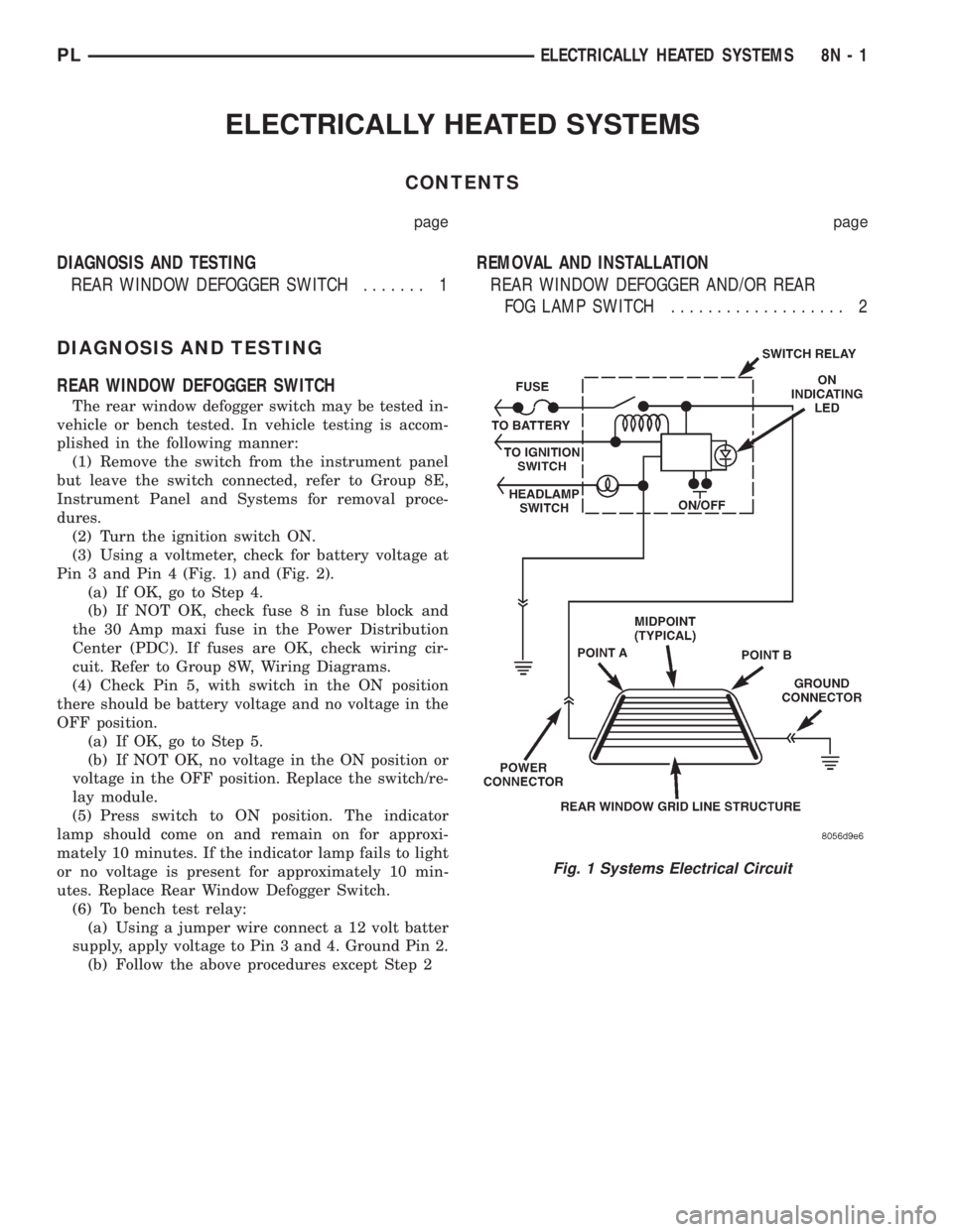
(3) Using a voltmeter, check for battery voltage at
Pin 3 and Pin 4 (Fig. 1) and (Fig. 2).
(a) If OK, go to Step 4.
(b) If NOT OK, check fuse 8 in fuse block and
the 30 Amp maxi fuse in the Power Distribution
Center (PDC). If fuses are OK, check wiring cir-
cuit. Refer to Group 8W, Wiring Diagrams.
(4) Check Pin 5, with switch in the ON position
there should be battery voltage and no voltage in the
OFF position.
(a) If OK, go to Step 5.
(b) If NOT OK, no voltage in the ON position or
voltage in the OFF position. Replace the switch/re-
lay module.
(5) Press switch to ON position. The indicator
lamp should come on and remain on for approxi-
mately 10 minutes. If the indicator lamp fails to light
or no voltage is present for approximately 10 min-
utes. Replace Rear Window Defogger Switch.
(6) To bench test relay:
(a) Using a jumper wire connect a 12 volt batter
supply, apply voltage to Pin 3 and 4. Ground Pin 2.
(b) Follow the above procedures except Step 2
Fig. 1 Systems Electrical Circuit
PLELECTRICALLY HEATED SYSTEMS 8N - 1
Page 373 of 1200
DIAGNOSIS AND TESTING
REMOTE KEYLESS ENTRY CONDITION
Use an analog voltmeter for the following test.
REMOTE KEYLESS ENTRY GENERAL CHECKS
BEFORE OTHER CHECKS.
(1) Check if door locks operate properly. If not OK,
repair as necessary.
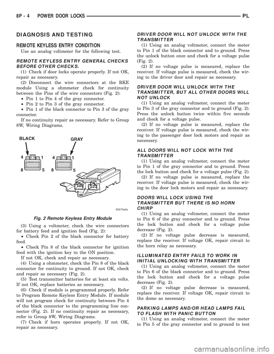
(2) Disconnect the wire connectors at the RKE
module Using a ohmmeter check for continuity
between the Pins of the wire connectors (Fig. 2):
²Pin 1 to Pin 4 of the gray connector.
²Pin 2 to Pin 3 of the gray connector.
²Pin 1 of the black connector to Pin 3 of the gray
connector.
If no continuity repair as necessary. Refer to Group
8W, Wiring Diagrams.
(3) Using a voltmeter, check the wire connectors
for battery feed and ignition feed (Fig. 2):
²Check Pin 2 of the black connector for battery
feed.
²Check Pin 8 of the black connector for ignition
feed with the ignition key in the ON position.
If not OK, check and repair as necessary.
(4) Using a ohmmeter, check the Pin 8 of the black
connector for continuity to ground. If not OK, check
and repair as necessary (Fig. 2).
(5) Test transmitter batteries for at least six volts.
If not OK, replace batteries as necessary.
(6) Check if module is programmed properly. Refer
to Program Remote Keyless Entry Module. If module
will not program check for continuity between Pin 4
of the black connector to the programming line con-
nector (Fig. 2). If no continuity repair as necessary,
refer to Group 8W, Wiring Diagrams.
(7) Check if horn operates properly. If not OK,
repair as necessary.
DRIVER DOOR WILL NOT UNLOCK WITH THE
TRANSMITTER
(1) Using an analog voltmeter, connect the meter
to Pin 1 of the black connector and to ground. Press
the unlock button once and check for a voltage pulse
(Fig. 2).
(2) If no voltage pulse is measured, replace the
receiver. If voltage pulse is measured, check the wir-
ing to the driver door and repair as necessary.
DRIVER DOOR WILL UNLOCK WITH THE
TRANSMITTER, BUT ALL OTHER DOORS WILL
NOT UNLOCK
(1) Using an analog voltmeter, connect the meter
to Pin 3 of the gray connector and to ground (Fig. 2).
Press the unlock button twice within five seconds
and check for a voltage pulse.
(2) If no voltage pulse is measured, replace the
receiver. If voltage pulse is measured, check the wir-
ing to the passenger door lock motors and repair as
necessary.
ALL DOORS WILL NOT LOCK WITH THE
TRANSMITTER
(1) Using an analog voltmeter, connect the meter
to Pin 1 of the gray connector and to ground. Press
the lock button and check for a voltage pulse (Fig. 2).
(2) If no voltage pulse is measured, replace the
receiver. If voltage pulse is measured, check the wir-
ing to the door lock motors and repair as necessary.
DOORS WILL LOCK USING THE
TRANSMITTER BUT THERE IS NO HORN
CHIRP
(1) Using an analog voltmeter, connect the meter
to Pin 6 of the gray connector and to ground. Press
the lock button and check for a voltage pulse
decrease (Fig. 2).
(2) If no voltage pulse decrease is measured,
replace the receiver. If voltage OK, repair circuit to
the horn relay as necessary.
ILLUMINATED ENTRY FAILS TO WORK IN
INITIAL UNLOCKING WITH TRANSMITTER
(1) Using an analog voltmeter, connect the meter
to Pin 6 of the black connector and to ground. Press
the lock button and check for a voltage pulse
decrease (Fig. 2).
(2) If no voltage pulse decrease is measured,
replace the receiver. If voltage OK, repair circuit to
the dome as necessary.
PARKING LAMPS AND/OR HEAD LAMPS FAIL
TO FLASH WITH PANIC BUTTON
(1) Using an analog voltmeter, connect the meter
to Pin 5 of the gray connector and to ground to test
Fig. 2 Remote Keyless Entry Module
8P - 4 POWER DOOR LOCKSPL
Page 386 of 1200
POWER MIRRORS
CONTENTS
page page
GENERAL INFORMATION
INTRODUCTION........................ 1
DIAGNOSIS AND TESTING
MIRROR MOTOR....................... 2MIRROR SWITCH TEST.................. 1
GENERAL INFORMATION
INTRODUCTION
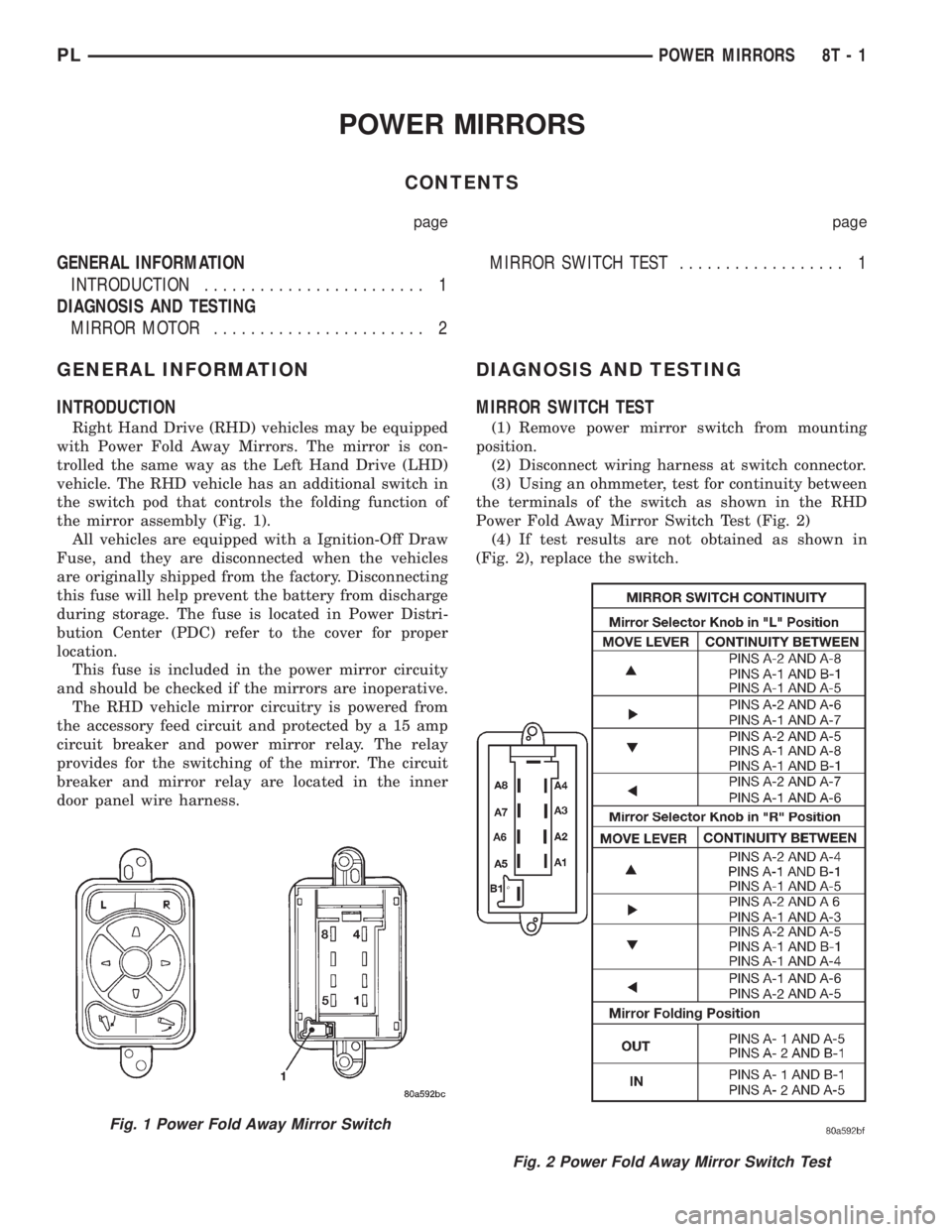
Right Hand Drive (RHD) vehicles may be equipped
with Power Fold Away Mirrors. The mirror is con-
trolled the same way as the Left Hand Drive (LHD)
vehicle. The RHD vehicle has an additional switch in
the switch pod that controls the folding function of
the mirror assembly (Fig. 1).
All vehicles are equipped with a Ignition-Off Draw
Fuse, and they are disconnected when the vehicles
are originally shipped from the factory. Disconnecting
this fuse will help prevent the battery from discharge
during storage. The fuse is located in Power Distri-
bution Center (PDC) refer to the cover for proper
location.
This fuse is included in the power mirror circuity
and should be checked if the mirrors are inoperative.
The RHD vehicle mirror circuitry is powered from
the accessory feed circuit and protected by a 15 amp
circuit breaker and power mirror relay. The relay
provides for the switching of the mirror. The circuit
breaker and mirror relay are located in the inner
door panel wire harness.
DIAGNOSIS AND TESTING
MIRROR SWITCH TEST
(1) Remove power mirror switch from mounting
position.
(2) Disconnect wiring harness at switch connector.
(3) Using an ohmmeter, test for continuity between
the terminals of the switch as shown in the RHD
Power Fold Away Mirror Switch Test (Fig. 2)
(4) If test results are not obtained as shown in
(Fig. 2), replace the switch.
Fig. 1 Power Fold Away Mirror Switch
Fig. 2 Power Fold Away Mirror Switch Test
PLPOWER MIRRORS 8T - 1
Page 398 of 1200
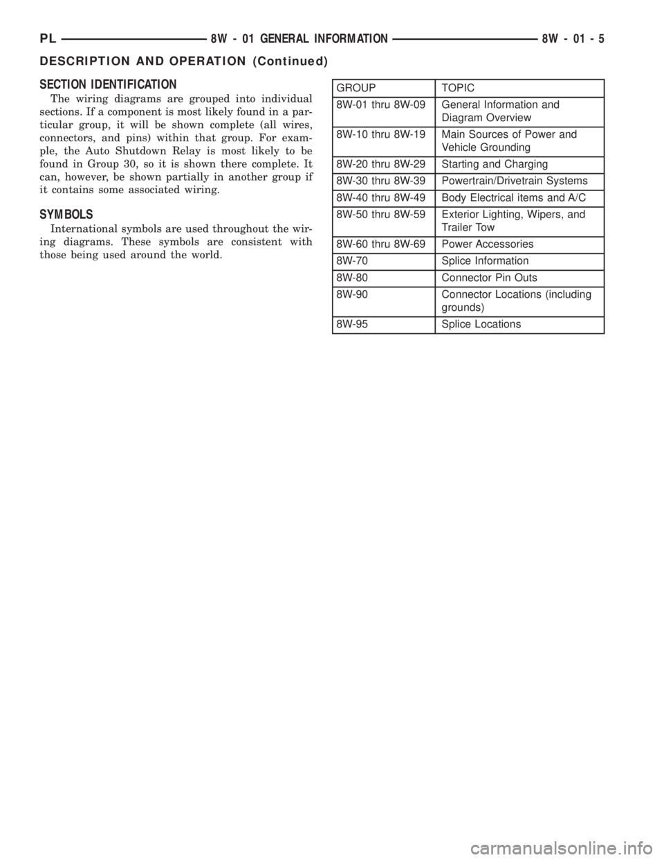
SECTION IDENTIFICATION
The wiring diagrams are grouped into individual
sections. If a component is most likely found in a par-
ticular group, it will be shown complete (all wires,
connectors, and pins) within that group. For exam-
ple, the Auto Shutdown Relay is most likely to be
found in Group 30, so it is shown there complete. It
can, however, be shown partially in another group if
it contains some associated wiring.
SYMBOLS
International symbols are used throughout the wir-
ing diagrams. These symbols are consistent with
those being used around the world.
GROUP TOPIC
8W-01 thru 8W-09 General Information and
Diagram Overview
8W-10 thru 8W-19 Main Sources of Power and
Vehicle Grounding
8W-20 thru 8W-29 Starting and Charging
8W-30 thru 8W-39 Powertrain/Drivetrain Systems
8W-40 thru 8W-49 Body Electrical items and A/C
8W-50 thru 8W-59 Exterior Lighting, Wipers, and
Trailer Tow
8W-60 thru 8W-69 Power Accessories
8W-70 Splice Information
8W-80 Connector Pin Outs
8W-90 Connector Locations (including
grounds)
8W-95 Splice Locations
PL8W - 01 GENERAL INFORMATION 8W - 01 - 5
DESCRIPTION AND OPERATION (Continued)
Page 402 of 1200
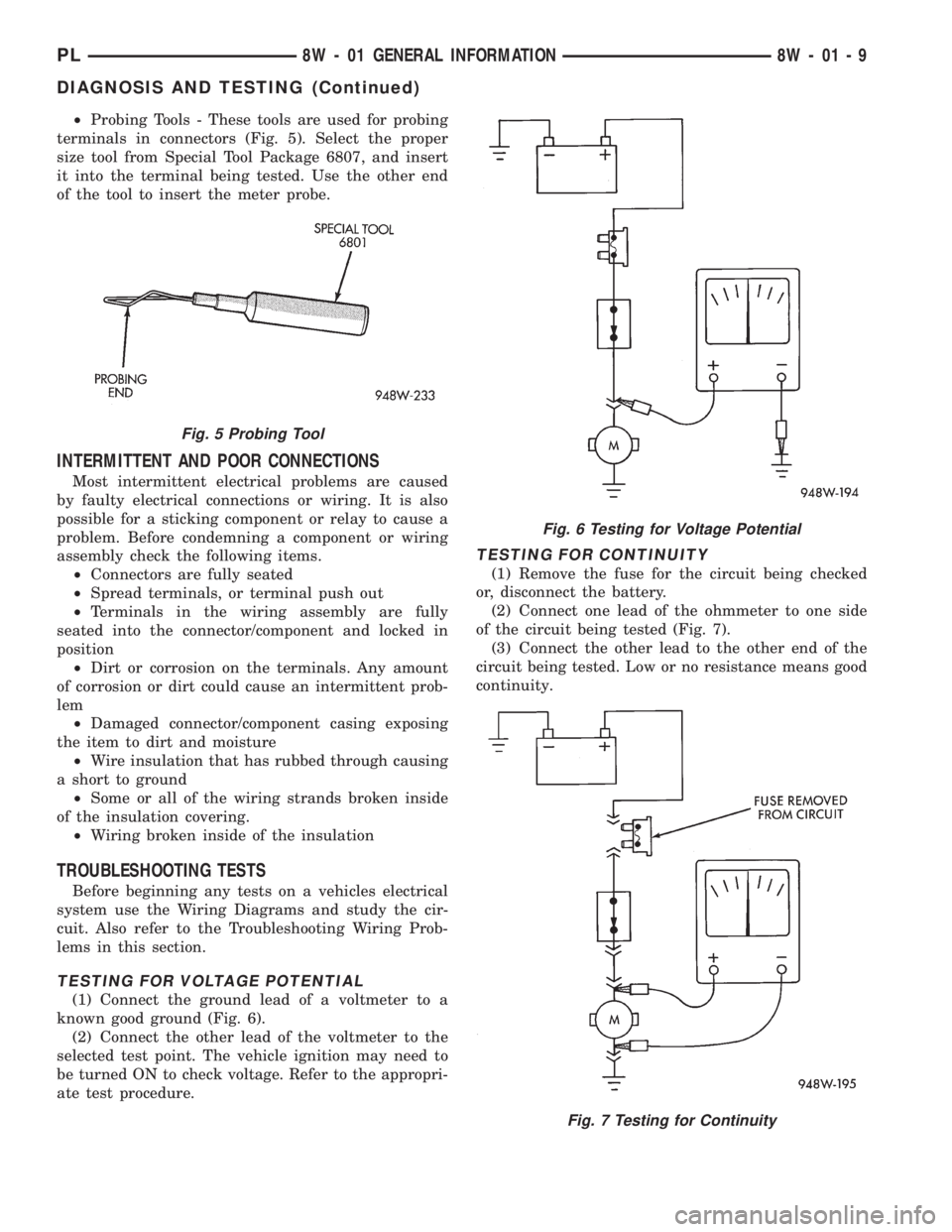
²Probing Tools - These tools are used for probing
terminals in connectors (Fig. 5). Select the proper
size tool from Special Tool Package 6807, and insert
it into the terminal being tested. Use the other end
of the tool to insert the meter probe.
INTERMITTENT AND POOR CONNECTIONS
Most intermittent electrical problems are caused
by faulty electrical connections or wiring. It is also
possible for a sticking component or relay to cause a
problem. Before condemning a component or wiring
assembly check the following items.
²Connectors are fully seated
²Spread terminals, or terminal push out
²Terminals in the wiring assembly are fully
seated into the connector/component and locked in
position
²Dirt or corrosion on the terminals. Any amount
of corrosion or dirt could cause an intermittent prob-
lem
²Damaged connector/component casing exposing
the item to dirt and moisture
²Wire insulation that has rubbed through causing
a short to ground
²Some or all of the wiring strands broken inside
of the insulation covering.
²Wiring broken inside of the insulation
TROUBLESHOOTING TESTS
Before beginning any tests on a vehicles electrical
system use the Wiring Diagrams and study the cir-
cuit. Also refer to the Troubleshooting Wiring Prob-
lems in this section.
TESTING FOR VOLTAGE POTENTIAL
(1) Connect the ground lead of a voltmeter to a
known good ground (Fig. 6).
(2) Connect the other lead of the voltmeter to the
selected test point. The vehicle ignition may need to
be turned ON to check voltage. Refer to the appropri-
ate test procedure.
TESTING FOR CONTINUITY
(1) Remove the fuse for the circuit being checked
or, disconnect the battery.
(2) Connect one lead of the ohmmeter to one side
of the circuit being tested (Fig. 7).
(3) Connect the other lead to the other end of the
circuit being tested. Low or no resistance means good
continuity.
Fig. 5 Probing Tool
Fig. 6 Testing for Voltage Potential
Fig. 7 Testing for Continuity
PL8W - 01 GENERAL INFORMATION 8W - 01 - 9
DIAGNOSIS AND TESTING (Continued)
Page 410 of 1200
8W-02 COMPONENT INDEX
Component Page
A/C Compressor Clutch..................8W-42
A/C Compressor Clutch Relay.............8W-42
A/C Cycling Switch.....................8W-42
A/C Heater Blower Motor................8W-42
A/C Heater Control.....................8W-42
A/C Pressure Switches...................8W-42
ABS Warning Lamp Relay................8W-35
Airbag Control Module...................8W-43
Airbags..............................8W-43
Antenna..............................8W-47
Ash Receiver Lamp.....................8W-44
Automatic Shut Down Relay..............8W-30
Back-Up Lamp Switch...................8W-51
Back-Up Lamps........................8W-51
Battery..............................8W-20
Battery Temperature Sensor..............8W-30
Blower Motor Resistor Block..............8W-42
Brake Warning Lamp Switch...........8W-40, 50
Camshaft Position Sensor................8W-30
Center High Mounted Stop Lamp..........8W-51
Cigar Lighter Relay.....................8W-41
Cigar Lighter/Power Outlet...............8W-41
Circuit Breakers.......................8W-11
Clockspring.....................8W-30, 41, 61
Clutch Pedal Position Switch...........8W-10, 21
Combination Flasher....................8W-52
Controller Anti-Lock Brake...............8W-35
Crankshaft Position Sensor...............8W-30
Data Link Connector....................8W-30
Daytime Running Lamp Module...........8W-50
Diode No. 1........................8W-15, 42
Diode No. 2......................8W-10, 11, 44
Diode No. 3......................8W-11,44,70
Dome Lamp...........................8W-44
Door Ajar Switches.....................8W-44
Door Jamb Switches....................8W-44
Door Lock Motors......................8W-61
Door Lock Motors......................8W-61
Door Lock Switches.....................8W-61
Duty Cycle Evap/Purge Solenoid...........8W-30
EGR Transducer Solenoid................8W-30
Engine Coolant Temperature Sensor........8W-30
Engine Oil Pressure Switch...............8W-40
Engine Starter Motor....................8W-21
Engine Starter Motor Relay...............8W-21
Fog Lamp Relays....................8W-50, 51
Fog Lamp Switches..................8W-50, 51
Fog Lamps.........................8W-50, 51
Fuel Injectors..........................8W-30
Fuel Pump Module.....................8W-30
Fuel Pump Relay.......................8W-30
Fuse Block............................8W-11Component Page
Fuses (FB)............................8W-11
Fuses (PDC)...........................8W-10
Fusible Link........................8W-20, 21
Generator.............................8W-20
Glove Box Lamp And Switch..............8W-44
Grounds..............................8W-15
Halo Lamp............................8W-44
Headlamp Dimmer And Optical Horn Switch .8W-50
Headlamp Leveling Motors...............8W-50
Headlamp Leveling Switch...............8W-50
Headlamp Switch.......................8W-50
Headlamps............................8W-50
High Speed Warning Module..............8W-40
Horn Relay...........................8W-41
Horn Switches.........................8W-41
Horns................................8W-41
IAT/Map Sensor........................8W-30
Idle Air Control Motor...................8W-30
Ignition Coil Pack......................8W-30
Ignition Switch........................8W-10
Illumination Lamps.....................8W-40
Immobilizer...........................8W-61
Immobilizer Engine Sensor............8W-30, 61
Indicator Lamps........................8W-40
Instrument Cluster.....................8W-40
Intermittent Wipe/Wash Switch............8W-53
Key-In Switch.........................8W-40
Knock Sensor..........................8W-30
License Lamps.........................8W-51
Map/Reading Lamps....................8W-44
Noise Supressor.....................8W-10, 30
Oxygen Sensors........................8W-30
Park Brake Switch...................8W-40, 50
Park/Neutral Position Switch...........8W-30, 51
Park/Turn Signal Lamps..............8W-50, 52
Power Distribution Center................8W-10
Power Folding Mirror Relay...............8W-62
Power Mirror Fuse Holder................8W-62
Power Mirrors.........................8W-62
Power Steering Pressure Switch...........8W-30
Power Sunroof Motor....................8W-64
Power Window Motors...................8W-60
Power Window Switches.................8W-60
Powertrain Control Module...............8W-30
PRNDL Lamp.........................8W-44
Radiator Fan Motor.....................8W-42
Radio................................8W-47
Rear Window Defogger..................8W-48
Rear Window Defogger Switch.............8W-48
Remote Keyless Entry Module.............8W-61
Remote Keyless Entry Program
Module Connector....................8W-61
PL8W - 02 COMPONENT INDEX 8W - 02 - 1
Page 411 of 1200
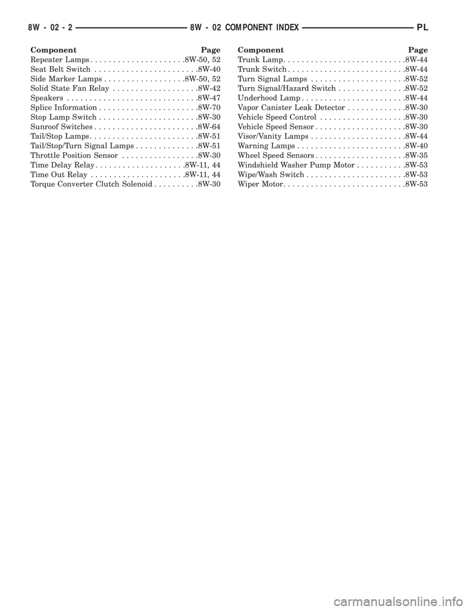
Component Page
Repeater Lamps.....................8W-50, 52
Seat Belt Switch.......................8W-40
Side Marker Lamps..................8W-50, 52
Solid State Fan Relay...................8W-42
Speakers.............................8W-47
Splice Information......................8W-70
Stop Lamp Switch......................8W-30
Sunroof Switches.......................8W-64
Tail/Stop Lamps........................8W-51
Tail/Stop/Turn Signal Lamps..............8W-51
Throttle Position Sensor.................8W-30
Time Delay Relay....................8W-11,44
Time Out Relay.....................8W-11,44
Torque Converter Clutch Solenoid..........8W-30Component Page
Trunk Lamp...........................8W-44
Trunk Switch..........................8W-44
Turn Signal Lamps.....................8W-52
Turn Signal/Hazard Switch...............8W-52
Underhood Lamp.......................8W-44
Vapor Canister Leak Detector.............8W-30
Vehicle Speed Control...................8W-30
Vehicle Speed Sensor....................8W-30
Visor/Vanity Lamps.....................8W-44
Warning Lamps........................8W-40
Wheel Speed Sensors....................8W-35
Windshield Washer Pump Motor...........8W-53
Wipe/Wash Switch......................8W-53
Wiper Motor...........................8W-53
8W - 02 - 2 8W - 02 COMPONENT INDEXPL
Page 412 of 1200
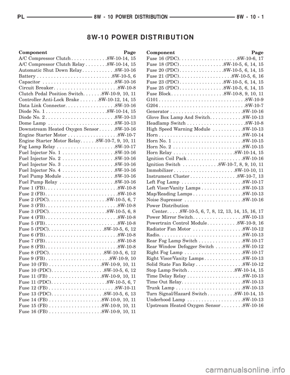
8W-10 POWER DISTRIBUTION
Component Page
A/C Compressor Clutch.............8W-10-14, 15
A/C Compressor Clutch Relay........8W-10-14, 15
Automatic Shut Down Relay............8W-10-16
Battery...........................8W-10-5, 6
Capacitor..........................8W-10-16
Circuit Breaker.......................8W-10-8
Clutch Pedal Position Switch.......8W-10-9, 10, 11
Controller Anti-Lock Brake.......8W-10-12, 14, 15
Data Link Connector..................8W-10-16
Diode No. 1......................8W-10-14, 15
Diode No. 2.........................8W-10-13
Dome Lamp........................8W-10-13
Downstream Heated Oxygen Sensor......8W-10-16
Engine Starter Motor..................8W-10-7
Engine Starter Motor Relay......8W-10-7, 9, 10, 11
Fog Lamp Relay.....................8W-10-17
Fuel Injector No. 1...................8W-10-16
Fuel Injector No. 2...................8W-10-16
Fuel Injector No. 3...................8W-10-16
Fuel Injector No. 4...................8W-10-16
Fuel Pump Module...................8W-10-16
Fuel Pump Relay....................8W-10-16
Fuse 1 (FB)..........................8W-10-8
Fuse 2 (FB)..........................8W-10-8
Fuse 2 (PDC).....................8W-10-5, 6, 7
Fuse 3 (FB)..........................8W-10-8
Fuse 3 (PDC).....................8W-10-5, 6, 8
Fuse 4 (FB)..........................8W-10-8
Fuse 5 (FB)..........................8W-10-8
Fuse 5 (PDC)....................8W-10-5, 6, 12
Fuse 6 (FB)..........................8W-10-8
Fuse 7 (FB)..........................8W-10-8
Fuse 8 (FB)..........................8W-10-8
Fuse 8 (PDC)....................8W-10-5, 6, 12
Fuse 9 (FB).......................8W-10-9, 10
Fuse 10 (FB)...................8W-10-9, 10, 11
Fuse 10 (PDC)...................8W-10-5, 6, 12
Fuse 11 (FB)...................8W-10-9, 10, 11
Fuse 11 (PDC)....................8W-10-5, 6, 7
Fuse 12 (FB)........................8W-10-11
Fuse 13 (PDC)...................8W-10-5, 6, 13
Fuse 14 (FB)...................8W-10-9, 10, 11
Fuse 15 (FB)...................8W-10-9, 10, 11
Fuse 16 (FB)...................8W-10-9, 10, 11Component Page
Fuse 16 (PDC).....................8W-10-6, 17
Fuse 18 (PDC)................8W-10-5, 6, 14, 15
Fuse 20 (PDC)................8W-10-5, 6, 14, 15
Fuse 21 (PDC)...................8W-10-5, 6, 16
Fuse 23 (PDC)................8W-10-5, 6, 14, 15
Fuse 25 (PDC)................8W-10-5, 6, 14, 15
Fuse Block...................8W-10-8, 9, 10, 11
G101...............................8W-10-9
G204...............................8W-10-7
Generator..........................8W-10-16
Glove Box Lamp And Switch............8W-10-13
Headlamp Switch.....................8W-10-8
High Speed Warning Module...........8W-10-13
Horn..............................8W-10-14
Horn No. 1.........................8W-10-15
Horn No. 2.........................8W-10-15
Horn Relay......................8W-10-14, 15
Ignition Coil Pack....................8W-10-16
Ignition Switch.............8W-10-7, 8, 9, 10, 11
Immobilizer......................8W-10-10, 11
Instrument Cluster.................8W-10-7, 13
Left Fog Lamp......................8W-10-17
Left Visor/Vanity Lamps...............8W-10-13
Map/Reading Lamps..................8W-10-13
Noise Supressor.....................8W-10-16
Power Distribution
Center.....8W-10-5, 6, 7, 8, 12, 13, 14, 15, 16, 17
Power Mirror Switch..................8W-10-13
Powertrain Control Module...........8W-10-9, 16
Radiator Fan Motor..................8W-10-12
Radio..............................8W-10-13
Rear Fog Lamp Switch................8W-10-17
Rear Window Defogger Switch..........8W-10-12
Right Fog Lamp.....................8W-10-17
Right Visor/Vanity Lamps..............8W-10-13
Solid State Fan Relay.................8W-10-12
Stop Lamp Switch.................8W-10-14, 15
Time Delay Relay....................8W-10-13
Time Out Relay......................8W-10-13
Trunk Lamp........................8W-10-13
Turn Signal/Hazard Switch..........8W-10-14, 15
Underhood Lamp....................8W-10-13
Upstream Heated Oxygen Sensor........8W-10-16
PL8W - 10 POWER DISTRIBUTION 8W - 10 - 1