catalytic converter DODGE NEON 1999 Service Repair Manual
[x] Cancel search | Manufacturer: DODGE, Model Year: 1999, Model line: NEON, Model: DODGE NEON 1999Pages: 1200, PDF Size: 35.29 MB
Page 256 of 1200
train Control Module (PCM) with an input signal
(voltage). The signal represents throttle blade posi-
tion. As the position of the throttle blade changes,
the resistance of the TPS changes.
The PCM supplies approximately 5 volts to the
TPS. The TPS output voltage (input signal to the
powertrain control module) represents throttle blade
position. The TPS output voltage to the PCM varies
from approximately 0.38 volts to 1.2 volts at mini-
mum throttle opening (idle) to a maximum of 3.1
volts to 4.4 volts at wide open throttle.
Along with inputs from other sensors, the PCM
uses the TPS input to determine current engine oper-
ating conditions. The PCM also adjusts fuel injector
pulse width and ignition timing based on these
inputs.
IGNITION SWITCH
In the RUN position, the ignition switch connects
power from the Power Distribution Center (PDC) to a
30 amp fuse in the fuse block, back to a bus bar in
the PDC. The bus bar feeds circuits for the Power-
train Control Module (PCM), duty cycle purge sole-
noid, EGR solenoid, and ABS system. The bus bar in
the PDC feeds the coil side of the radiator fan relay,
A/C compressor clutch relay, and the fuel pump relay.
It also feeds the Airbag Control Module (ACM)
LOCK KEY CYLINDER
The lock cylinder is inserted in the end of the
housing opposite the ignition switch. The ignition key
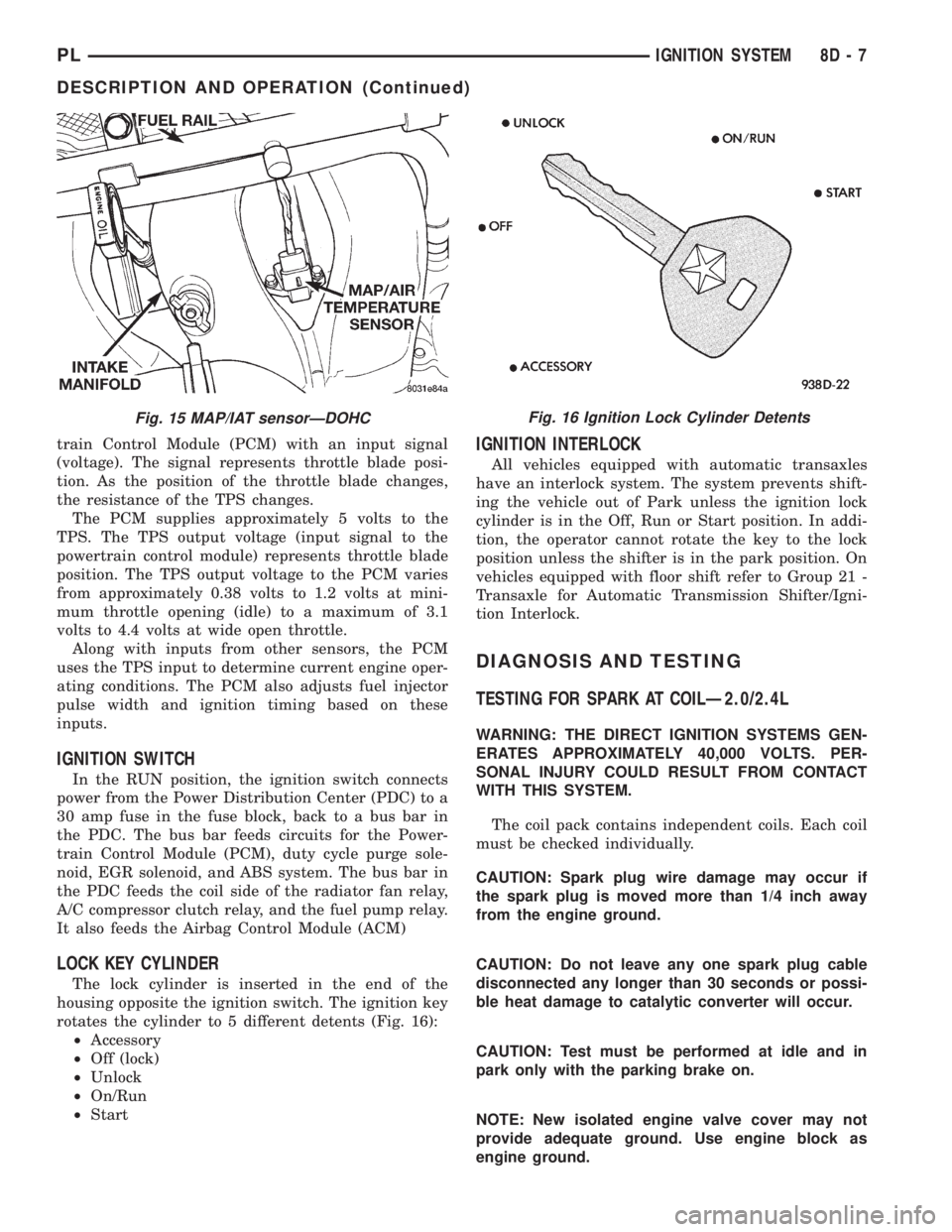
rotates the cylinder to 5 different detents (Fig. 16):
²Accessory
²Off (lock)
²Unlock
²On/Run
²Start
IGNITION INTERLOCK
All vehicles equipped with automatic transaxles
have an interlock system. The system prevents shift-
ing the vehicle out of Park unless the ignition lock
cylinder is in the Off, Run or Start position. In addi-
tion, the operator cannot rotate the key to the lock
position unless the shifter is in the park position. On
vehicles equipped with floor shift refer to Group 21 -
Transaxle for Automatic Transmission Shifter/Igni-
tion Interlock.
DIAGNOSIS AND TESTING
TESTING FOR SPARK AT COILÐ2.0/2.4L
WARNING: THE DIRECT IGNITION SYSTEMS GEN-
ERATES APPROXIMATELY 40,000 VOLTS. PER-
SONAL INJURY COULD RESULT FROM CONTACT
WITH THIS SYSTEM.
The coil pack contains independent coils. Each coil
must be checked individually.
CAUTION: Spark plug wire damage may occur if
the spark plug is moved more than 1/4 inch away
from the engine ground.
CAUTION: Do not leave any one spark plug cable
disconnected any longer than 30 seconds or possi-
ble heat damage to catalytic converter will occur.
CAUTION: Test must be performed at idle and in
park only with the parking brake on.
NOTE: New isolated engine valve cover may not
provide adequate ground. Use engine block as
engine ground.
Fig. 15 MAP/IAT sensorÐDOHCFig. 16 Ignition Lock Cylinder Detents
PLIGNITION SYSTEM 8D - 7
DESCRIPTION AND OPERATION (Continued)
Page 257 of 1200
Use a new spark plug and spark plug cable
for the following test.
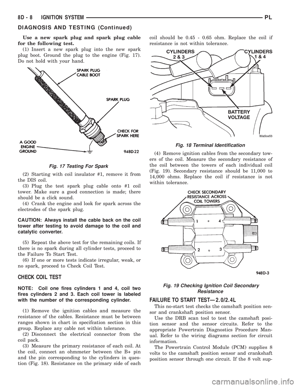
(1) Insert a new spark plug into the new spark
plug boot. Ground the plug to the engine (Fig. 17).
Do not hold with your hand.
(2) Starting with coil insulator #1, remove it from
the DIS coil.
(3) Plug the test spark plug cable onto #1 coil
tower. Make sure a good connection is made; there
should be a click sound.
(4) Crank the engine and look for spark across the
electrodes of the spark plug.
CAUTION: Always install the cable back on the coil
tower after testing to avoid damage to the coil and
catalytic converter.
(5) Repeat the above test for the remaining coils. If
there is no spark during all cylinder tests, proceed to
the Failure To Start Test.
(6) If one or more tests indicate irregular, weak, or
no spark, proceed to Check Coil Test.
CHECK COIL TEST
NOTE: Coil one fires cylinders 1 and 4, coil two
fires cylinders 2 and 3. Each coil tower is labeled
with the number of the corresponding cylinder.
(1) Remove the ignition cables and measure the
resistance of the cables. Resistance must be between
ranges shown in chart in specifcation section in this
group. Replace any cable not within tolerance.
(2) Disconnect the electrical connector from the
coil pack.
(3) Measure the primary resistance of each coil. At
the coil, connect an ohmmeter between the B+ pin
and the pin corresponding to the cylinders in ques-
tion (Fig. 18). Resistance on the primary side of eachcoil should be 0.45 - 0.65 ohm. Replace the coil if
resistance is not within tolerance.
(4) Remove ignition cables from the secondary tow-
ers of the coil. Measure the secondary resistance of
the coil between the towers of each individual coil
(Fig. 19). Secondary resistance should be 11,000 to
14,000 ohms. Replace the coil if resistance is not
within tolerance.
FAILURE TO START TESTÐ2.0/2.4L
This no-start test checks the camshaft position sen-
sor and crankshaft position sensor.
Use the DRB scan tool to test the camshaft posi-
tion sensor and the sensor circuits. Refer to the
appropriate Powertrain Diagnostics Procedure Man-
ual. Refer to the wiring diagrams section for circuit
information.
The Powertrain Control Module (PCM) supplies 8
volts to the camshaft position sensor and crankshaft
position sensor through one circuit. If the 8 volt sup-
Fig. 17 Testing For Spark
Fig. 18 Terminal Identification
Fig. 19 Checking Ignition Coil Secondary
Resistance
8D - 8 IGNITION SYSTEMPL
DIAGNOSIS AND TESTING (Continued)
Page 676 of 1200
CONNECTOR/GROUND LOCATIONS (RHD)
For items not shown in this section a N/S is placed
in the Fig. column.
Connector
Name/NumberColor Location Fig.
A/C
Compressor
ClutchBK Top of A/C
Compressor8
A/C Cycling
SwitchBK Center of
HVAC HousingN/S
A/C-Heater
Blower MotorBK Right Side of
HVAC HousingN/S
A/C-Heater
ControlBK Rear of HVAC
Control13
A/C Hi-Pressure
SwitchGY Top of A/C
Compressor8
A/C Low
Pressure SwitchBK Left Rear Cowl
PanelN/S
Airbag Control
ModuleYL Rear of
Gearshift11
Ash Receiver
LampBK At Lamp N/S
Back-Up Lamp
SwitchGY Top of
Transmission3
Battery Left Front of
Engine
Compartment6
Battery Temp
SensorBK Bottom of
Battery Tray6
Blower Motor
Resistor BlockNAT Left Side Cowl
PanelN/S
Brake Warning
Lamp SwitchBK Right Frame
RailN/S
C101 BR Top of I.P. 13
C102 BK Top of I.P. 13
C103 BL Top of I.P. 13
C105 BK Right Kick
PanelN/S
C108 BK Left Lower
CowlN/S
C160 LT/GY Left Fender
Side Shield5
C161 BK Left Fender
Side Shield5Connector
Name/NumberColor Location Fig.
C170 NAT Top Center of
I.P.N/S
C205 BL Right Kick
PanelN/S
C206 BL Top Left of I.P. 13
C225 RD Left Kick Panel 9
C230 GY Right Kick
Panel14
C231 BL Left Side of I.P. 13
C301 GY Right B-Pillar 15
C303 GY Left B-Pillar 15
C309 BK Left Rear
Wheel Well18
C340 BK Left Rear
Quarter Panel20
C341 BK Right Rear
Quarter Panel20
Camshaft
Position SensorBK Left Side of
Engine7
CHMSL BK Rear of Lamp 18
Cigar Lighter/
Power OutletBottom Center
of Stack13
Clockspring NAT Rear of
Steering Wheel10
Clutch Pedal
Position SwitchBK Top of Clutch
Pedal2
Controller
Anti-Lock BrakeBK Left Rear of
Engine
CompartmentN/S
Crankshaft
Position SensorBK Rear of Engine 7
Data Link
ConnectorBK Left Side of
Steering
ColumnN/S
Dome Lamp BK LT C-Pillar 20
Downstream
Heated Oxygen
SensorBK Rear of
Catalytic
ConverterN/S
Driver Side
Airbag SquibYL Rear of
Clockspring12
Duty Cycle
Evap/Purge
SolenoidGY RT Strut Tower 10
PL8W - 90 CONNECTOR/GROUND LOCATIONS 8W - 90 - 23
DESCRIPTION AND OPERATION (Continued)
Page 816 of 1200
EXHAUST SYSTEM AND INTAKE MANIFOLD
CONTENTS
page page
GENERAL INFORMATION
CATALYTIC CONVERTER................... 4
EXHAUST BALL JOINT COUPLING.......... 1
EXHAUST FLEX-JOINT COUPLING (LEV)...... 2
EXHAUST GAS RECIRCULATION (EGR)
SYSTEM.............................. 3
EXHAUST SYSTEMS...................... 1
HEAT SHIELDS.......................... 3
DESCRIPTION AND OPERATION
EXHAUST MANIFOLD..................... 3
INTAKE MANIFOLD DOHC................. 3
INTAKE MANIFOLD SOHC................. 3
DIAGNOSIS AND TESTING
EXHAUST SYSTEM DIAGNOSIS CHART...... 4REMOVAL AND INSTALLATION
EXHAUST MANIFOLD.................... 11
EXHAUST PIPE AND MUFFLER............. 4
INTAKE MANIFOLDÐDOHC ENGINE......... 9
INTAKE MANIFOLDÐSOHC ENGINE......... 6
CLEANING AND INSPECTION
EXHAUST MANIFOLD.................... 12
INTAKE MANIFOLD DOHC................ 12
INTAKE MANIFOLD SOHC................ 12
SPECIFICATIONS
TORQUE CHART........................ 12
GENERAL INFORMATION
EXHAUST SYSTEMS
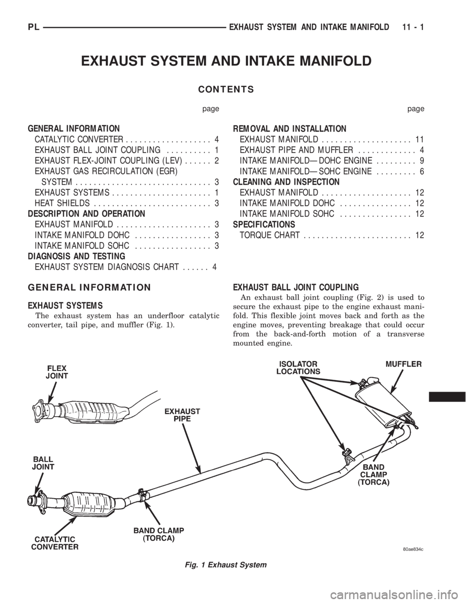
The exhaust system has an underfloor catalytic
converter, tail pipe, and muffler (Fig. 1).
EXHAUST BALL JOINT COUPLING
An exhaust ball joint coupling (Fig. 2) is used to
secure the exhaust pipe to the engine exhaust mani-
fold. This flexible joint moves back and forth as the
engine moves, preventing breakage that could occur
from the back-and-forth motion of a transverse
mounted engine.
Fig. 1 Exhaust System
PLEXHAUST SYSTEM AND INTAKE MANIFOLD 11 - 1
Page 817 of 1200
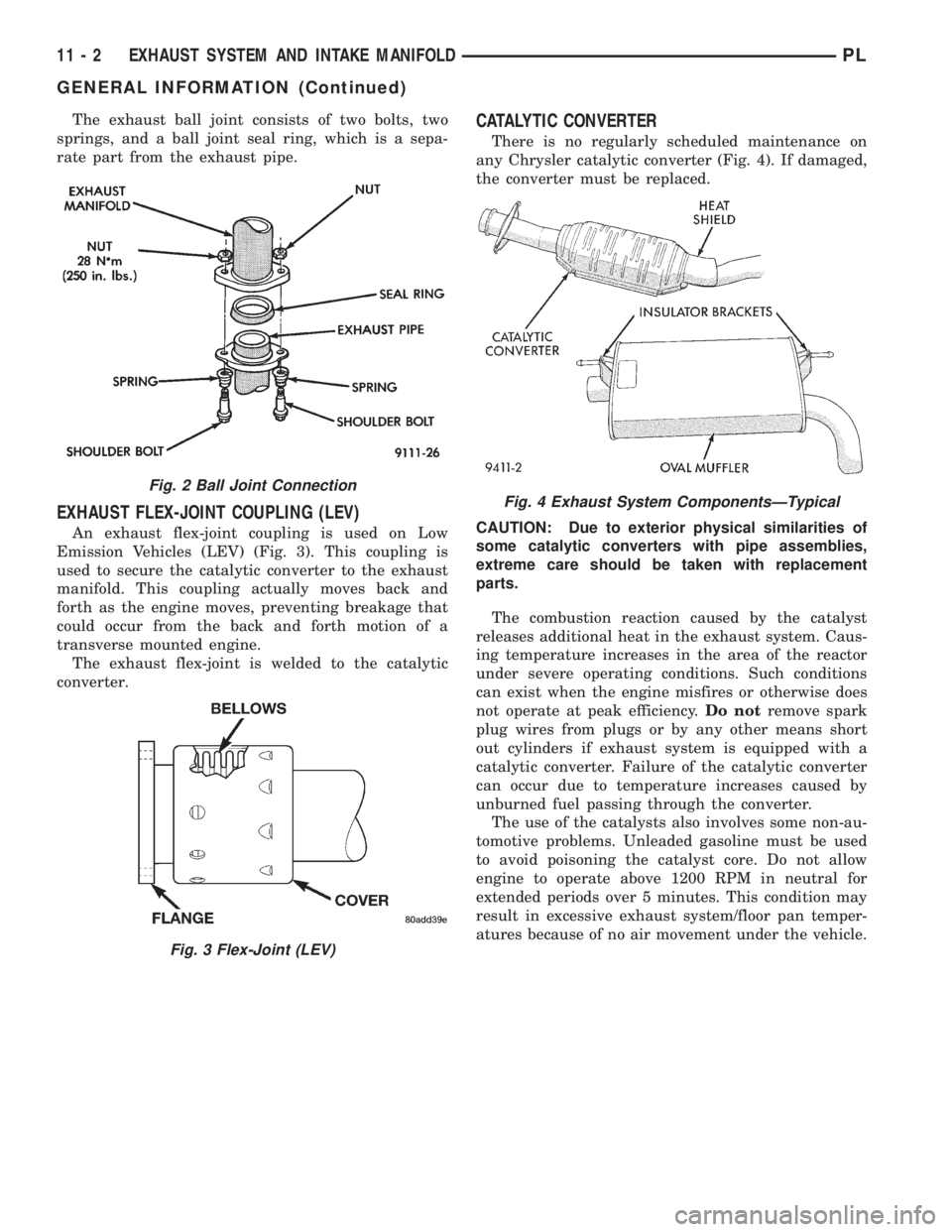
The exhaust ball joint consists of two bolts, two
springs, and a ball joint seal ring, which is a sepa-
rate part from the exhaust pipe.
EXHAUST FLEX-JOINT COUPLING (LEV)
An exhaust flex-joint coupling is used on Low
Emission Vehicles (LEV) (Fig. 3). This coupling is
used to secure the catalytic converter to the exhaust
manifold. This coupling actually moves back and
forth as the engine moves, preventing breakage that
could occur from the back and forth motion of a
transverse mounted engine.
The exhaust flex-joint is welded to the catalytic
converter.
CATALYTIC CONVERTER
There is no regularly scheduled maintenance on
any Chrysler catalytic converter (Fig. 4). If damaged,
the converter must be replaced.
CAUTION: Due to exterior physical similarities of
some catalytic converters with pipe assemblies,
extreme care should be taken with replacement
parts.
The combustion reaction caused by the catalyst
releases additional heat in the exhaust system. Caus-
ing temperature increases in the area of the reactor
under severe operating conditions. Such conditions
can exist when the engine misfires or otherwise does
not operate at peak efficiency.Do notremove spark
plug wires from plugs or by any other means short
out cylinders if exhaust system is equipped with a
catalytic converter. Failure of the catalytic converter
can occur due to temperature increases caused by
unburned fuel passing through the converter.
The use of the catalysts also involves some non-au-
tomotive problems. Unleaded gasoline must be used
to avoid poisoning the catalyst core. Do not allow
engine to operate above 1200 RPM in neutral for
extended periods over 5 minutes. This condition may
result in excessive exhaust system/floor pan temper-
atures because of no air movement under the vehicle.
Fig. 2 Ball Joint Connection
Fig. 3 Flex-Joint (LEV)
Fig. 4 Exhaust System ComponentsÐTypical
11 - 2 EXHAUST SYSTEM AND INTAKE MANIFOLDPL
GENERAL INFORMATION (Continued)
Page 819 of 1200
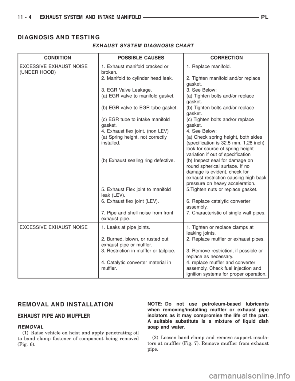
DIAGNOSIS AND TESTING
REMOVAL AND INSTALLATION
EXHAUST PIPE AND MUFFLER
REMOVAL
(1) Raise vehicle on hoist and apply penetrating oil
to band clamp fastener of component being removed
(Fig. 6).NOTE: Do not use petroleum-based lubricants
when removing/installing muffler or exhaust pipe
isolators as it may compromise the life of the part.
A suitable substitute is a mixture of liquid dish
soap and water.
(2) Loosen band clamp and remove support insula-
tors at muffler (Fig. 7). Remove muffler from exhaust
pipe.
EXHAUST SYSTEM DIAGNOSIS CHART
CONDITION POSSIBLE CAUSES CORRECTION
EXCESSIVE EXHAUST NOISE
(UNDER HOOD)1. Exhaust manifold cracked or
broken.1. Replace manifold.
2. Manifold to cylinder head leak. 2. Tighten manifold and/or replace
gasket.
3. EGR Valve Leakage. 3. See Below:
(a) EGR valve to manifold gasket. (a) Tighten bolts and/or replace
gasket.
(b) EGR valve to EGR tube gasket. (b) Tighten bolts and/or replace
gasket.
(c) EGR tube to intake manifold
gasket.(c) Tighten bolts and/or replace
gasket.
4. Exhaust flex joint. (non LEV) 4. See Below:
(a) Spring height, not correctly
installed.(a) Check spring height, both sides
(specification is 32.5 mm, 1.28 inch)
look for source of spring height
variation if out of specification
(b) Exhaust sealing ring defective. (b) Inspect seal for damage on
round spherical surface. If no
damage is evident, check for
exhaust restriction causing high back
pressure on heavy acceleration.
5. Exhaust Flex joint to manifold
leak (LEV).5.Tighten nuts or replace gasket.
6. Exhaust flex joint (LEV). 6. Replace catalytic converter
assembly.
7. Pipe and shell noise from front
exhaust pipe.7. Characteristic of single wall pipes.
EXCESSIVE EXHAUST NOISE 1. Leaks at pipe joints. 1. Tighten or replace clamps at
leaking joints.
2. Burned, blown, or rusted out
exhaust pipe or muffler.2. Replace muffler or exhaust pipes.
3. Restriction in muffler or tailpipe. 3. Remove restriction, if possible or
replace as necessary.
4. Catalytic converter material in
muffler.4. replace muffler and converter
assembly. Check fuel injection and
ignition systems for proper operation.
11 - 4 EXHAUST SYSTEM AND INTAKE MANIFOLDPL
Page 820 of 1200
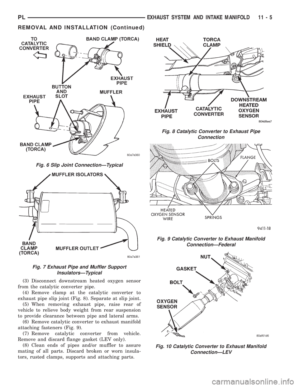
(3) Disconnect downstream heated oxygen sensor
from the catalytic converter pipe.
(4) Remove clamp at the catalytic converter to
exhaust pipe slip joint (Fig. 8). Separate at slip joint.
(5) When removing exhaust pipe, raise rear of
vehicle to relieve body weight from rear suspension
to provide clearance between pipe and lateral arms.
(6) Remove catalytic converter to exhaust manifold
attaching fasteners (Fig. 9).
(7) Remove catalytic converter from vehicle.
Remove and discard flange gasket (LEV only).
(8) Clean ends of pipes and/or muffler to assure
mating of all parts. Discard broken or worn insula-
tors, rusted clamps, supports and attaching parts.
Fig. 6 Slip Joint ConnectionÐTypical
Fig. 7 Exhaust Pipe and Muffler Support
InsulatorsÐTypical
Fig. 8 Catalytic Converter to Exhaust Pipe
Connection
Fig. 9 Catalytic Converter to Exhaust Manifold
ConnectionÐFederal
Fig. 10 Catalytic Converter to Exhaust Manifold
ConnectionÐLEV
PLEXHAUST SYSTEM AND INTAKE MANIFOLD 11 - 5
REMOVAL AND INSTALLATION (Continued)
Page 869 of 1200
deterioration, the fuel injection system uses two
heated oxygen sensors. One sensor upstream of the
catalytic convertor, one downstream of the convertor.
The PCM compares the reading from the sensors to
calculate the catalytic convertor oxygen storage
capacity and converter efficiency. Also, the PCM uses
the upstream heated oxygen sensor input when
adjusting injector pulse width.
When the catalytic converter efficiency drops below
emission standards, the PCM stores a diagnostic
trouble code and illuminates the malfunction indica-
tor lamp (MIL).
The O2S sensors produce voltages from 0 to 1 volt,
depending upon the oxygen content of the exhaust
gas in the exhaust manifold. When a large amount of
oxygen is present (caused by a lean air/fuel mixture),
the sensors produces a low voltage. When there is a
lesser amount present (rich air/fuel mixture) it pro-
duces a higher voltage. By monitoring the oxygen
content and converting it to electrical voltage, the
sensors act as a rich- lean switch.
The oxygen sensors are equipped with a heating
element that keeps the sensors at proper operating
temperature during all operating modes. Maintaining
correct sensor temperature at all times allows the
system to enter into closed loop operation sooner.
Also, it allows the system to remain in closed loop
operation during periods of extended idle.
In Closed Loop operation the PCM monitors the
O2S sensor input (along with other inputs) and
adjusts the injector pulse width accordingly. During
Open Loop operation the PCM ignores the O2 sensor
input. The PCM adjusts injector pulse width based
on preprogrammed (fixed) values and inputs from
other sensors.
The Automatic Shutdown (ASD) relay supplies bat-
tery voltage to both the upstream and downstream
heated oxygen sensors. The oxygen sensors are
equipped with a heating element. The heating ele-
ments reduce the time required for the sensors to
reach operating temperature.
UPSTREAM OXYGEN SENSOR
The input from the upstream heated oxygen sensor
tells the PCM the oxygen content of the exhaust gas.
Based on this input, the PCM fine tunes the air-fuel
ratio by adjusting injector pulse width.
The sensor input switches from 0 to 1 volt, depend-
ing upon the oxygen content of the exhaust gas in
the exhaust manifold. When a large amount of oxy-
gen is present (caused by a lean air-fuel mixture), the
sensor produces voltage as low as 0.1 volt. When
there is a lesser amount of oxygen present (rich air-
fuel mixture) the sensor produces a voltage as high
as 1.0 volt. By monitoring the oxygen content and
converting it to electrical voltage, the sensor acts as
a rich-lean switch.The heating element in the sensor provides heat to
the sensor ceramic element. Heating the sensor
allows the system to enter into closed loop operation
sooner. Also, it allows the system to remain in closed
loop operation during periods of extended idle.
In Closed Loop, the PCM adjusts injector pulse
width based on the upstream heated oxygen sensor
input along with other inputs. In Open Loop, the
PCM adjusts injector pulse width based on prepro-
grammed (fixed) values and inputs from other sen-
sors.
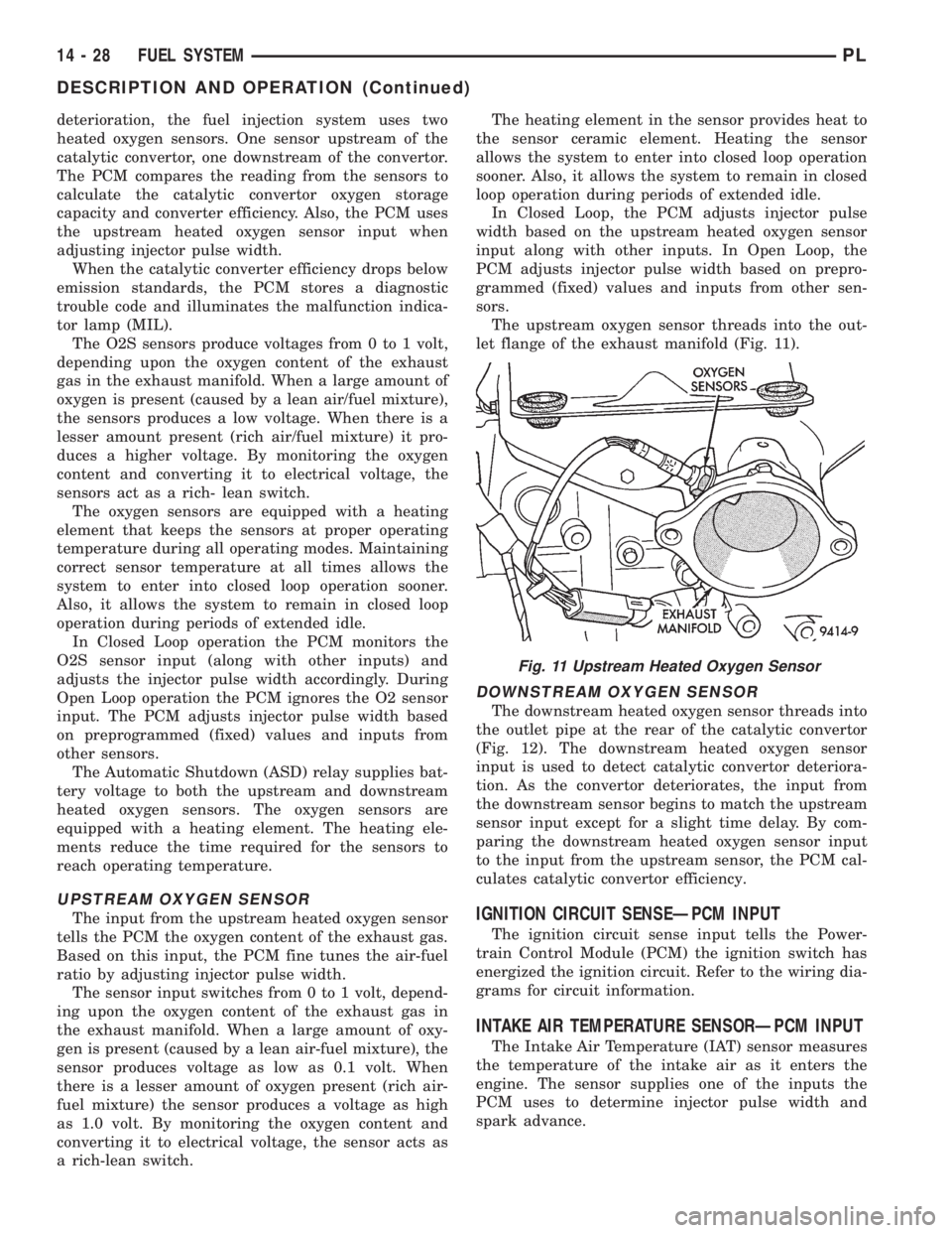
The upstream oxygen sensor threads into the out-
let flange of the exhaust manifold (Fig. 11).
DOWNSTREAM OXYGEN SENSOR
The downstream heated oxygen sensor threads into
the outlet pipe at the rear of the catalytic convertor
(Fig. 12). The downstream heated oxygen sensor
input is used to detect catalytic convertor deteriora-
tion. As the convertor deteriorates, the input from
the downstream sensor begins to match the upstream
sensor input except for a slight time delay. By com-
paring the downstream heated oxygen sensor input
to the input from the upstream sensor, the PCM cal-
culates catalytic convertor efficiency.
IGNITION CIRCUIT SENSEÐPCM INPUT
The ignition circuit sense input tells the Power-
train Control Module (PCM) the ignition switch has
energized the ignition circuit. Refer to the wiring dia-
grams for circuit information.
INTAKE AIR TEMPERATURE SENSORÐPCM INPUT
The Intake Air Temperature (IAT) sensor measures
the temperature of the intake air as it enters the
engine. The sensor supplies one of the inputs the
PCM uses to determine injector pulse width and
spark advance.
Fig. 11 Upstream Heated Oxygen Sensor
14 - 28 FUEL SYSTEMPL
DESCRIPTION AND OPERATION (Continued)
Page 1170 of 1200
Following is a description of each system monitor,
and its DTC.
Refer to the appropriate Powertrain Diagnos-
tics Procedures manual for diagnostic proce-
dures.
HEX 66, and 7AÐOXYGEN SENSOR (O2S)
MONITOR
Effective control of exhaust emissions is achieved
by an oxygen feedback system. The most important
element of the feedback system is the O2S. The O2S
is located in the exhaust path. Once it reaches oper-
ating temperature 300É to 350ÉC (572É to 662ÉF), the
sensor generates a voltage that is inversely propor-
tional to the amount of oxygen in the exhaust. The
information obtained by the sensor is used to calcu-
late the fuel injector pulse width. This maintains a
14.7 to 1 air fuel (A/F) ratio. At this mixture ratio,
the catalyst works best to remove hydrocarbons (HC),
carbon monoxide (CO) and nitrous oxide (NOx) from
the exhaust.
The O2S is also the main sensing element for the
EGR, Catalyst and Fuel Monitors.
The O2S may fail in any or all of the following
manners:
²Slow response rate
²Reduced output voltage
²Dynamic shift
²Shorted or open circuits
Response rate is the time required for the sensor to
switch from lean to rich once it is exposed to a richer
than optimum A/F mixture or vice versa. As the sen-
sor starts malfunctioning, it could take longer to
detect the changes in the oxygen content of the
exhaust gas.
The output voltage of the O2S ranges from 0 to 1
volt. A good sensor can easily generate any output
voltage in this range as it is exposed to different con-
centrations of oxygen. To detect a shift in the A/F
mixture (lean or rich), the output voltage has to
change beyond a threshold value. A malfunctioning
sensor could have difficulty changing beyond the
threshold value.
HEX 67, 69, 7C, and 7DÐOXYGEN SENSOR
HEATER MONITOR
If there is an oxygen sensor (O2S) DTC as well as
a O2S heater DTC, the O2S fault MUST be repaired
first. After the O2S fault is repaired, verify that the
heater circuit is operating correctly.
Effective control of exhaust emissions is achieved
by an oxygen feedback system. The most important
element of the feedback system is the O2S. The O2S
is located in the exhaust path. Once it reaches oper-
ating temperature 300É to 350ÉC (572 Éto 662ÉF), the
sensor generates a voltage that is inversely propor-
tional to the amount of oxygen in the exhaust. Theinformation obtained by the sensor is used to calcu-
late the fuel injector pulse width. This maintains a
14.7 to 1 Air Fuel (A/F) ratio. At this mixture ratio,
the catalyst works best to remove hydrocarbons (HC),
carbon monoxide (CO) and nitrogen oxide (NOx) from
the exhaust.
The voltage readings taken from the O2S are very
temperature sensitive. The readings are not accurate
below 300ÉC. Heating of the O2S is done to allow the
engine controller to shift to closed loop control as
soon as possible. The heating element used to heat
the O2S must be tested to ensure that it is heating
the sensor properly.
The O2S circuit is monitored for a drop in voltage.
The sensor output is used to test the heater by iso-
lating the effect of the heater element on the O2S
output voltage from the other effects.
HEX 2EÐEGR MONITOR
The Powertrain Control Module (PCM) performs
an on-board diagnostic check of the EGR system.
The EGR system consists of two main components:
a vacuum solenoid back pressure transducer and a
vacuum operated valve. The EGR monitor is used to
test whether the EGR system is operating within
specifications. The diagnostic check activates only
during selected engine/driving conditions. When the
conditions are met, the EGR is turned off (solenoid
energized) and the O2S compensation control is mon-
itored. Turning off the EGR shifts the air fuel (A/F)
ratio in the lean direction. The O2S data should indi-
cate an increase in the O2 concentration in the com-
bustion chamber when the exhaust gases are no
longer recirculated. While this test does not directly
measure the operation of the EGR system, it can be
inferred from the shift in the O2S data whether the
EGR system is operating correctly. Because the O2S
is being used, the O2S test must pass its test before
the EGR test.
HEX 6A,6B, 6C, 6D, 6E, AE, and AFÐMISFIRE
MONITOR
Excessive engine misfire results in increased cata-
lyst temperature and causes an increase in HC emis-
sions. Severe misfires could cause catalyst damage.
To prevent catalytic convertor damage, the PCM
monitors engine misfire.
The Powertrain Control Module (PCM) monitors
for misfire during most engine operating conditions
(positive torque) by looking at changes in the crank-
shaft speed. If a misfire occurs the speed of the
crankshaft will vary more than normal.
HEX 76, 77, 78, and 79ÐFUEL SYSTEM
MONITOR
To comply with clean air regulations, vehicles are
equipped with catalytic converters. These converters
PLEMISSION CONTROL SYSTEMS 25 - 7
DESCRIPTION AND OPERATION (Continued)
Page 1171 of 1200
reduce the emission of hydrocarbons, oxides of nitro-
gen and carbon monoxide. The catalyst works best
when the air fuel (A/F) ratio is at or near the opti-
mum of 14.7 to 1.
The PCM is programmed to maintain the optimum
air/fuel ratio of 14.7 to 1. This is done by making
short term corrections in the fuel injector pulse width
based on the O2S output. The programmed memory
acts as a self calibration tool that the engine control-
ler uses to compensate for variations in engine spec-
ifications, sensor tolerances and engine fatigue over
the life span of the engine. By monitoring the actual
air-fuel ratio with the O2S (short term) and multiply-
ing that with the program long-term (adaptive) mem-
ory and comparing that to the limit, it can be
determined whether it will pass an emissions test. If
a malfunction occurs such that the PCM cannot
maintain the optimum A/F ratio, then the MIL will
be illuminated.
HEX 70, and B4ÐCATALYST MONITOR
To comply with clean air regulations, vehicles are
equipped with catalytic converters. These converters
reduce the emission of hydrocarbons, oxides of nitro-
gen and carbon monoxide.
Normal vehicle miles or engine misfire can cause a
catalyst to decay. A meltdown of the ceramic core can
cause a reduction of the exhaust passage. This can
increase vehicle emissions and deteriorate engine
performance, driveability and fuel economy.
The catalyst monitor uses dual oxygen sensors
(O2S's) to monitor the efficiency of the converter. The
dual O2Ss strategy is based on the fact that as a cat-
alyst deteriorates, its oxygen storage capacity and its
efficiency are both reduced. By monitoring the oxy-
gen storage capacity of a catalyst, its efficiency can
be indirectly calculated. The upstream O2S is used to
detect the amount of oxygen in the exhaust gas
before the gas enters the catalytic converter. The
PCM calculates the A/F mixture from the output of
the O2S. A low voltage indicates high oxygen content
(lean mixture). A high voltage indicates a low content
of oxygen (rich mixture).
When the upstream O2S detects a lean condition,
there is an abundance of oxygen in the exhaust gas.
A functioning converter would store this oxygen so it
can use it for the oxidation of HC and CO. As the
converter absorbs the oxygen, there will be a lack of
oxygen downstream of the converter. The output of
the downstraem O2S will indicate limited activity in
this condition.
As the converter loses the ability to store oxygen,
the condition can be detected from the behavior of
the downstream O2S. When the efficiency drops, no
chemical reaction takes place. This means the con-
centration of oxygen will be the same downstream as
upstream. The output voltage of the downstreamO2S copies the voltage of the upstream sensor. The
only difference is a time lag (seen by the PCM)
between the switching of the O2S's.
To monitor the system, the number of lean-to-rich
switches of upstream and downstream O2S's is
counted. The ratio of downstream switches to
upstream switches is used to determine whether the
catalyst is operating properly. An effective catalyst
will have fewer downstream switches than it has
upstream switches i.e., a ratio closer to zero. For a
totally ineffective catalyst, this ratio will be one-to-
one, indicating that no oxidation occurs in the device.
The system must be monitored so that when cata-
lyst efficiency deteriorates and exhaust emissions
increase to over the legal limit, the MIL (check
engine lamp) will be illuminated.
HEX A0, A1, B7, and B8ÐLEAK DETECTION
PUMP MONITOR
The leak detection assembly incorporates two pri-
mary functions: it must detect a leak in the evapora-
tive system and seal the evaporative system so the
leak detection test can be run.
The primary components within the assembly are:
A three port solenoid that activates both of the func-
tions listed above; a pump which contains a switch,
two check valves and a spring/diaphragm, a canister
vent valve (CVV) seal which contains a spring loaded
vent seal valve.
Immediately after a cold start, between predeter-
mined temperature thresholds limits, the three port
solenoid is briefly energized. This initializes the
pump by drawing air into the pump cavity and also
closes the vent seal. During non test conditions the
vent seal is held open by the pump diaphragm
assembly which pushes it open at the full travel posi-
tion. The vent seal will remain closed while the
pump is cycling due to the reed switch triggering of
the three port solenoid that prevents the diaphragm
assembly from reaching full travel. After the brief
initialization period, the solenoid is de-energized
allowing atmospheric pressure to enter the pump
cavity, thus permitting the spring to drive the dia-
phragm which forces air out of the pump cavity and
into the vent system. When the solenoid is energized
and de energized, the cycle is repeated creating flow
in typical diaphragm pump fashion. The pump is con-
trolled in 2 modes:
Pump Mode:The pump is cycled at a fixed rate to
achieve a rapid pressure build in order to shorten the
overall test length.
Test Mode:The solenoid is energized with a fixed
duration pulse. Subsequent fixed pulses occur when
the diaphragm reaches the Switch closure point.
The spring in the pump is set so that the system
will achieve an equalized pressure of about 7.5º H20.
The cycle rate of pump strokes is quite rapid as the
25 - 8 EMISSION CONTROL SYSTEMSPL
DESCRIPTION AND OPERATION (Continued)