automatic transmission DODGE NEON 1999 Service Service Manual
[x] Cancel search | Manufacturer: DODGE, Model Year: 1999, Model line: NEON, Model: DODGE NEON 1999Pages: 1200, PDF Size: 35.29 MB
Page 1009 of 1200
CAUTION: When reinstalling driveshafts, new drive-
shaft retaining clips must be used. Do not reuse old
clips. Failure to use new clips may result in disen-
gagement of inner constant±velocity joint.
CAUTION: The exhaust flex joint must be discon-
nected from the exhaust manifold anytime the
engine is lowered. If the engine is lowered while the
flex pipe is attached, damage will occur.
(14) Remove bolts securing exhaust flex joint to
exhaust manifold. Disconnect exhaust pipe from
manifold.
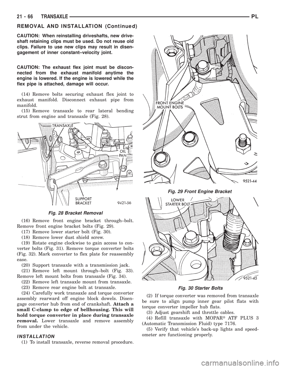
(15) Remove transaxle to rear lateral bending
strut from engine and transaxle (Fig. 28).
(16) Remove front engine bracket through±bolt.
Remove front engine bracket bolts (Fig. 29).
(17) Remove lower starter bolt (Fig. 30).
(18) Remove lower dust shield screw.
(19) Rotate engine clockwise to gain access to con-
verter bolts (Fig. 31). Remove torque converter bolts
(Fig. 32). Mark converter to flex plate for reassembly
ease.
(20) Support transaxle with a transmission jack.
(21) Remove left mount through±bolt (Fig. 33).
Remove left mount bolts from transaxle (Fig. 34).
(22) Remove left transaxle mount from transaxle.
(23) Remove rear engine bolt at transaxle.
(24) Carefully work transaxle and torque converter
assembly rearward off engine block dowels. Disen-
gage converter hub from end of crankshaft.Attach a
small C-clamp to edge of bellhousing. This will
hold torque converter in place during transaxle
removal.Lower transaxle and remove assembly
from under the vehicle.
INSTALLATION
(1) To install transaxle, reverse removal procedure.(2) If torque converter was removed from transaxle
be sure to align pump inner gear pilot flats with
torque converter impeller hub flats.
(3) Adjust gearshift and throttle cables.
(4) Refill transaxle with MOPARtATF PLUS 3
(Automatic Transmission Fluid) type 7176.
(5) Verify that vehicle's back-up lights and speed-
ometer are functioning properly.
Fig. 28 Bracket Removal
Fig. 29 Front Engine Bracket
Fig. 30 Starter Bolts
21 - 66 TRANSAXLEPL
REMOVAL AND INSTALLATION (Continued)
Page 1056 of 1200
SPECIFICATIONS
31TH AUTOMATIC TRANSAXLE
Type...........Automatic three speed with torque
converter and integral differential
Torque Converter
Diameter...............241 millimeters (9.48 in.)
Oil Capacity..............8.6 Liters (18.25 pints)
OilType..........MopartATF PLUS 3 Type 7176
Cooling Method........Water Heat Exchanger and/
or air to oil heat exchanger
Lubrication......Pump (internal-external gear-type
Gear Ratios
Transmission Portion
First Gear..............................2.69
Second Gear.............................1.55
Third Gear..............................1.00
Reverse Gear............................2.10
Pump Clearances
Outer Gear To Pocket.............0.045-0.141mm
(0.0018-0.0056 in.)
Outer Gear Side Clearance.........0.020-0.046mm
(0.0008-0.0018 in.)
Inner Gear Side Clearance.........0.020-0.046mm
(0.0008-0.0018 in.)
Tapered Roller Bearing Settings
Differential Assembly . . .6 to 12 in. lbs. Drag Torque
Output Hub............0to3in.lbs. Drag Torque
Transfer Shaft.........0.002 to 0.010 in. End Play
Overall Drag At Output Hub . . .3 to 16 in. lbs. Drag
Torque
Clutch Pack Clearances
Front Clutch (Not Adjustable)........1.27-2.79mm
(0.050-0.110 in.)
Rear Clutch.........0.71-1.10mm (0.028-0.043 in.)
Band Adjustment
Kickdown, Backed Off From
8N²m (72 in. lbs.)...............21/4Turns
Low-Reverse, Backed Off From
5N²m (41 in. lbs.)................31/2Turns
31TH TRANSAXLE TORQUE SPECIFICATIONS
DESCRIPTION TORQUE
Bell Housing Cover Bolts......12N´m(105 in. lbs.)
Cooler Hose To Rad. Conn......12N´m(105 in. lbs.)
Cooler Line Conn............28N´m(250 in. lbs.)
Diff. Bear. Ret. To Case Bolt . . .34 N´m (300 in. lbs.)
Diff. Cover To Case Bolt.......19N´m(165 in. lbs.)
Exten. Hous. To Case Bolt.....28N´m(250 in. lbs.)Flex Plate To Crankshaft Bolts . . .95 N´m (70 ft. lbs.)
Flex Plate To Torque
Conv. Bolts................68N´m(50ft.lbs.)
Fluid Filter Screw.............5N´m(45in.lbs.)
Front Motor Mount Bolt........54N´m(40ft.lbs.)
Governor Counterweight
Screw...................28N´m(250 in. lbs.)
Governor To Support Bolt.......7N´m(60in.lbs.)
Kickdown Band Adj. Lock Nut . . .47 N´m (35 ft. lbs.)
Left Motor Mount Bolts........54N´m(40ft.lbs.)
Lower Bell Housing
Cover Screw...............41N´m(30ft.lbs.)
Manual Cable To Trans.
Case Bolt................28N´m(250 in. lbs.)
Manual Control Lever Screw . . .12 N´m (105 in. lbs.)
Oil Pan To Trans. Case Screw . .19 N´m (165 in. lbs.)
Output Gear Strap Bolts........23N´m(17ft.lbs.)
Output Shaft Nut...........271 N´m (200 ft. lbs.)
Park/Neutral Switch...........34N´m(25ft.lbs.)
Pressure Check Plug...........5N´m(45in.lbs.)
Pump To Case Bolts..........31N´m(275 in. lbs.)
Reaction Shaft Assembly Bolt . .28 N´m (250 in. lbs.)
Rear Cover To Case Screw.....19N´m(165 in. lbs.)
Reverse Band Adj. Lock Nut . . .14 N´m (125 in. lbs.)
Reverse Band Shaft Plug........7N´m(60in.lbs.)
Ring Gear Screw..............95N´m(70ft.lbs.)
Speedo. To Ext. Hous. Screw.....7N´m(60in.lbs.)
Sprag Ret. To Transfer
Case Bolt................28N´m(250 in. lbs.)
Starter To Trans. Bell Bolts.....54N´m(40ft.lbs.)
Stirrup Strap Ret. Bolts.......23N´m(200 in. lbs.)
Throttle Cable To Trans.
Case Bolt................12N´m(105 in. lbs.)
Throttle Lever To Trans.
Shaft Bolts...............12N´m(105 in. lbs.)
Trans. To Cyl. Block Bolt.......95N´m(70ft.lbs.)
Transfer Shaft Nut..........271 N´m (200 ft. lbs.)
Transfer Gear Strap Bolts......23N´m(17ft.lbs.)
Valve Body Assy. To
Case Bolts...............12N´m(105 in. lbs.)
Valve Body Screw..............5N´m(45in.lbs.)
PLTRANSAXLE 21 - 113
Page 1064 of 1200
TRANSAXLE
CONTENTS
page page
DESCRIPTION AND OPERATION
BRAKE TRANSMISSION SHIFT INTERLOCK
(BTSI) SYSTEM........................ 1
DIAGNOSIS AND TESTING
BRAKE TRANSMISSION SHIFT INTERLOCK
(BTSI) SYSTEM........................ 1REMOVAL AND INSTALLATION
BRAKE TRANSMISSION SHIFT INTERLOCK
(BTSI) CABLE ASSEMBLY................ 2
ADJUSTMENTS
BRAKE TRANSMISSION SHIFT INTERLOCK
(BTSI) SYSTEM ADJUSTMENT............ 4
DESCRIPTION AND OPERATION
BRAKE TRANSMISSION SHIFT INTERLOCK
(BTSI) SYSTEM
The Brake Transmission Shift Interlock (BTSI)
System, is a cable and solenoid operated system. It
interconnects the automatic transmission floor
mounted shifter to the steering column ignition
switch. The BTSI system locks the shifter into the
PARK position. The BTSI system is engaged when-
ever the ignition switch is in the LOCK or ACCES-
SORY position.
An additional electrically activated feature will
prevent shifting out of the PARK position unless the
brake pedal is depressed at least one-half an inch. A
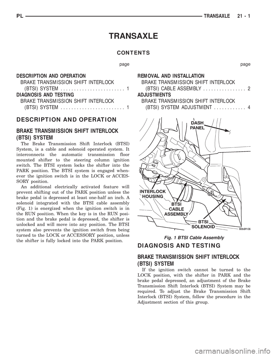
solenoid integrated with the BTSI cable assembly
(Fig. 1) is energized when the ignition switch is in
the RUN position. When the key is in the RUN posi-
tion and the brake pedal is depressed, the shifter is
unlocked and will move into any position. The BTSI
system also prevents the ignition switch from being
turned to the LOCK or ACCESSORY position, unless
the shifter is fully locked into the PARK position.
DIAGNOSIS AND TESTING
BRAKE TRANSMISSION SHIFT INTERLOCK
(BTSI) SYSTEM
If the ignition switch cannot be turned to the
LOCK position, with the shifter in PARK and the
brake pedal depressed, an adjustment of the Brake
Transmission Shift Interlock (BTSI) System may be
required. To adjust the Brake Transmission Shift
Interlock (BTSI) System, follow the procedure in the
Adjustment section of this group.
Fig. 1 BTSI Cable Assembly
PLTRANSAXLE 21 - 1
Page 1199 of 1200
VIN DECODING INFORMATION
POSITION INTERPRETATION CODE = DESCRIPTION
1 Country of origin 1 = United States
3 = Mexico
2 Make C = Chrysler
3 Vehicle Type 3 = Passenger Car
4 Passenger Safety E = Active Restraints, Driver and Passenger Airbags
5 Car Line S = Neon
6 Series M = DD5 5-Speed Manual Transmission
A = 3-Speed Automatic Transmission
7 Body Style7 = 4 Door Pillared Hardtop
8 Engine C = 2.0L 4 Cyl. 16V SOHC
A = 1.8L 4 Cyl. 16V SOHC
9 Check Digit See explanation in this section.
10 Model Year X = 1999
11 Assembly Plant D = Belvedere Assembly
T = Toluca
12 Thru 17 Build Sequence 6 Digit number assigned by assembly plant
E-MARK LABEL
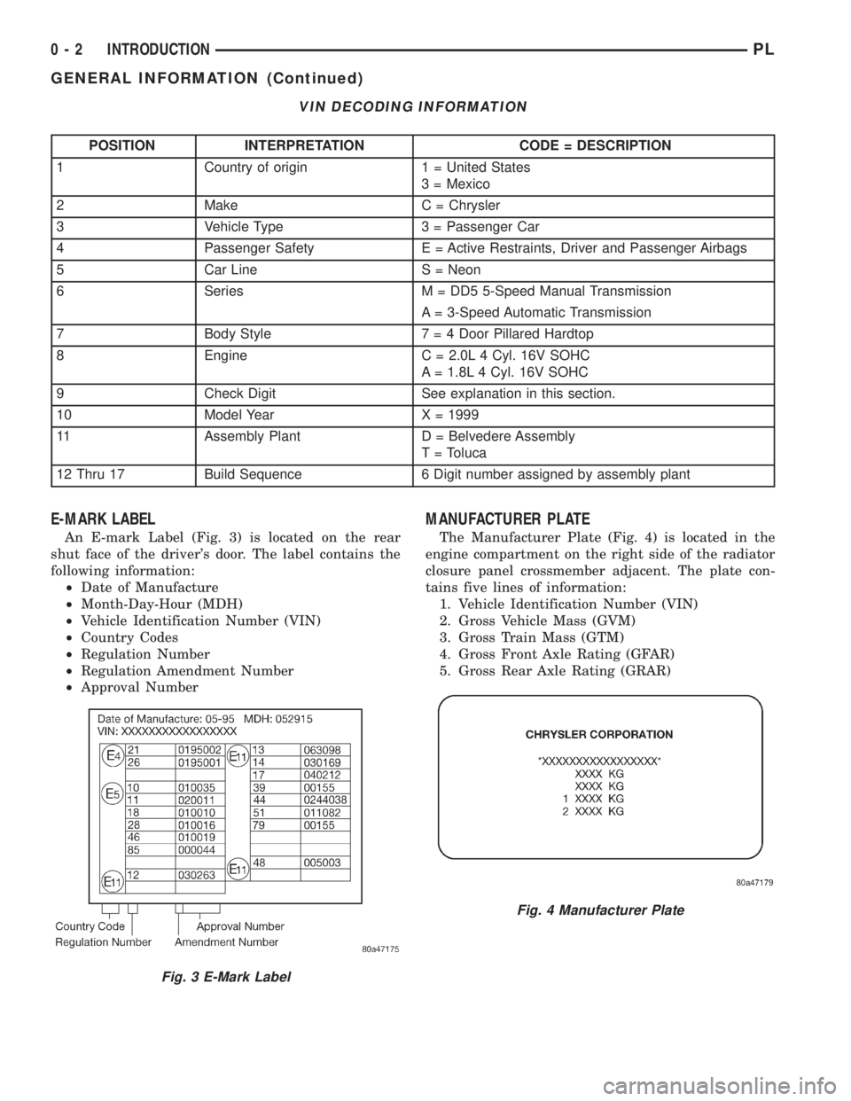
An E-mark Label (Fig. 3) is located on the rear
shut face of the driver's door. The label contains the
following information:
²Date of Manufacture
²Month-Day-Hour (MDH)
²Vehicle Identification Number (VIN)
²Country Codes
²Regulation Number
²Regulation Amendment Number
²Approval Number
MANUFACTURER PLATE
The Manufacturer Plate (Fig. 4) is located in the
engine compartment on the right side of the radiator
closure panel crossmember adjacent. The plate con-
tains five lines of information:
1. Vehicle Identification Number (VIN)
2. Gross Vehicle Mass (GVM)
3. Gross Train Mass (GTM)
4. Gross Front Axle Rating (GFAR)
5. Gross Rear Axle Rating (GRAR)
Fig. 3 E-Mark Label
Fig. 4 Manufacturer Plate
0 - 2 INTRODUCTIONPL
GENERAL INFORMATION (Continued)