key DODGE NEON 1999 Service Repair Manual
[x] Cancel search | Manufacturer: DODGE, Model Year: 1999, Model line: NEON, Model: DODGE NEON 1999Pages: 1200, PDF Size: 35.29 MB
Page 138 of 1200
(9) InstallA NEWhub and bearing assembly
retaining nut. Torque the hub and bearing assembly
retaining nut to 168 N´m (124 ft. lbs.).
(10) Install hub and bearing assembly dust cap.
(11) Install rear rotor.
(12) Install rear disc brake caliper on the adapter
(See Brake Shoe Removal).
(13) Install wheel and tire assemblies.
(14) Tighten wheel stud nuts to 129 N´m (95
ft.lbs.).
STOP LAMP SWITCH
REMOVE
(1) Depress and hold the brake pedal while rotat-
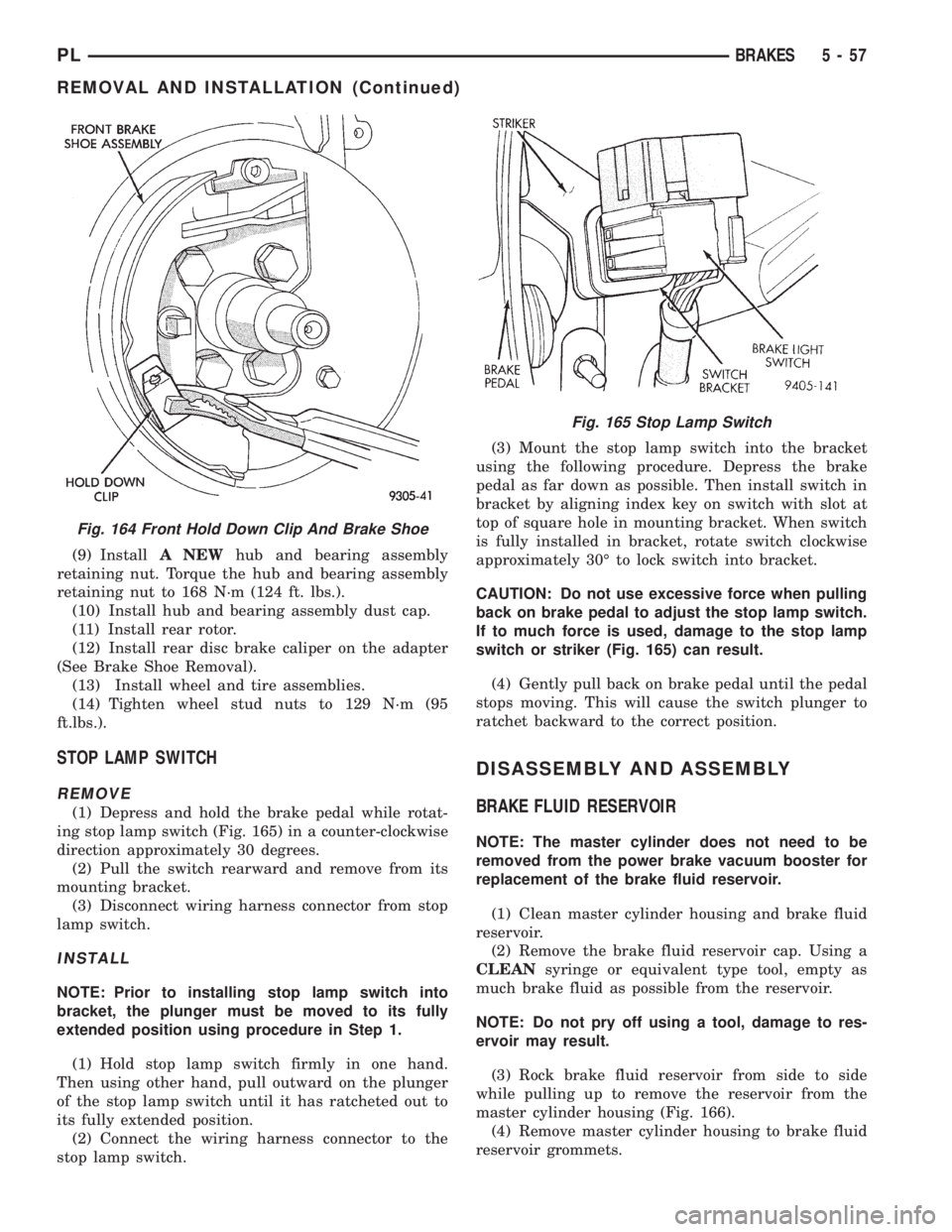
ing stop lamp switch (Fig. 165) in a counter-clockwise
direction approximately 30 degrees.
(2) Pull the switch rearward and remove from its
mounting bracket.
(3) Disconnect wiring harness connector from stop
lamp switch.
INSTALL
NOTE: Prior to installing stop lamp switch into
bracket, the plunger must be moved to its fully
extended position using procedure in Step 1.
(1) Hold stop lamp switch firmly in one hand.
Then using other hand, pull outward on the plunger
of the stop lamp switch until it has ratcheted out to
its fully extended position.
(2) Connect the wiring harness connector to the
stop lamp switch.(3) Mount the stop lamp switch into the bracket
using the following procedure. Depress the brake
pedal as far down as possible. Then install switch in
bracket by aligning index key on switch with slot at
top of square hole in mounting bracket. When switch
is fully installed in bracket, rotate switch clockwise
approximately 30É to lock switch into bracket.
CAUTION: Do not use excessive force when pulling
back on brake pedal to adjust the stop lamp switch.
If to much force is used, damage to the stop lamp
switch or striker (Fig. 165) can result.
(4) Gently pull back on brake pedal until the pedal
stops moving. This will cause the switch plunger to
ratchet backward to the correct position.
DISASSEMBLY AND ASSEMBLY
BRAKE FLUID RESERVOIR
NOTE: The master cylinder does not need to be
removed from the power brake vacuum booster for
replacement of the brake fluid reservoir.
(1) Clean master cylinder housing and brake fluid
reservoir.
(2) Remove the brake fluid reservoir cap. Using a
CLEANsyringe or equivalent type tool, empty as
much brake fluid as possible from the reservoir.
NOTE: Do not pry off using a tool, damage to res-
ervoir may result.
(3) Rock brake fluid reservoir from side to side
while pulling up to remove the reservoir from the
master cylinder housing (Fig. 166).
(4) Remove master cylinder housing to brake fluid
reservoir grommets.
Fig. 164 Front Hold Down Clip And Brake Shoe
Fig. 165 Stop Lamp Switch
PLBRAKES 5 - 57
REMOVAL AND INSTALLATION (Continued)
Page 146 of 1200
If old brake shoe return or hold down springs have
overheated or are damaged, replace. Overheating
indications are paint discoloration or distorted end
coils.
REAR DRUM BRAKE WHEEL CYLINDER
With brake drums removed, inspect the wheel cyl-
inder boots for evidence of a brake fluid leak. Visu-
ally check the boots for cuts, tears, or heat cracks. If
any of these conditions exist, the wheel cylinders
should be completely cleaned, inspected and new
parts installed.
If a wheel cylinder is leaking and the brake lining
material is saturated with brake fluid, the brake
shoes must be replaced.
CHASSIS TUBES AND HOSES
Flexible rubber hose is used at both front and rear
brakes. Inspection of brake hoses should be per-
formed whenever the brake system is serviced and
every 7,500 miles or 12 months, whichever comes
first (every engine oil change). Inspect hydraulic
brake hoses for severe surface cracking, scuffing,
worn spots or physical damage. If the fabric casing of
the rubber hose becomes exposed due to cracks or
abrasions in the rubber hose cover, the hose should
be replaced immediately. Eventual deterioration of
the hose can take place with possible burst failure.
Faulty installation can cause twisting, resulting in
wheel, tire, or chassis interference.
The steel brake tubing should be inspected periodi-
cally for evidence of corrosion, physical damage or con-
tact with moving or hot components of the vehicle.
REAR WHEEL HUB AND BEARING ASSEMBLY
The rear hub and bearing assembly is designed for
the life of the vehicle and should require no mainte-
nance. The following procedure may be used for eval-
uation of bearing condition.
With wheel and brake drum removed, rotate
flanged outer ring of hub. Excessive roughness, lat-
eral play or resistance to rotation may indicate dirt
intrusion or bearing failure. If the rear wheel bear-
ings exhibit these conditions during inspection, the
hub and bearing assembly should be replaced.Damaged bearing seals and resulting excessive
grease loss may also require bearing replacement.
Moderate grease loss from bearing is considered nor-
mal and should not require replacement of the hub
and bearing assembly.
ADJUSTMENTS
STOP LAMP SWITCH
(1) Remove stop lamp switch from its bracket by
rotating it approximately 30É in a counter-clockwise
direction.
(2) Disconnect wiring harness connector from stop
lamp switch.
(3) Hold stop lamp switch firmly in one hand.
Then using other hand, pull outward on the plunger
of the stop lamp switch until it has ratcheted out to
its fully extended position.
(4) Install the stop lamp switch into the bracket
using the following procedure. Depress the brake
pedal as far down as possible. Then while keeping
the brake pedal depressed, install the stop lamp
switch into the bracket by aligning index key on
switch with slot at top of square hole in mounting
bracket. When switch is fully installed in the square
hole of the bracket, rotate switch clockwise approxi-
mately 30É to lock the switch into the bracket.
CAUTION: Do not use excessive force when pulling
back on brake pedal to adjust the stop lamp switch.
If too much force is used, damage to the vacuum
booster, stop lamp switch or striker (Fig. 185) can
result.
(5) Connect the wiring harness connector to the
stop lamp switch.
(6) Gently pull back on brake pedal until the pedal
stops moving. This will cause the switch plunger
(Fig. 185) to ratchet backward to the correct position.
REAR DRUM BRAKE SHOE ADJUSTMENT
NOTE: Normally, self adjusting drum brakes will
not require manual brake shoe adjustment.
Although in the event of a brake reline it is advis-
able to make the initial adjustment manually to
speed up the adjusting time.
(1) Raise the vehicle so all wheels are free to turn.
See Hoisting Recommendations in the Lubrication
And Maintenance Section at the front of this service
manual.
(2) Remove rear brake adjusting hole rubber plug
(Fig. 186) from the rear brake shoe support plate.
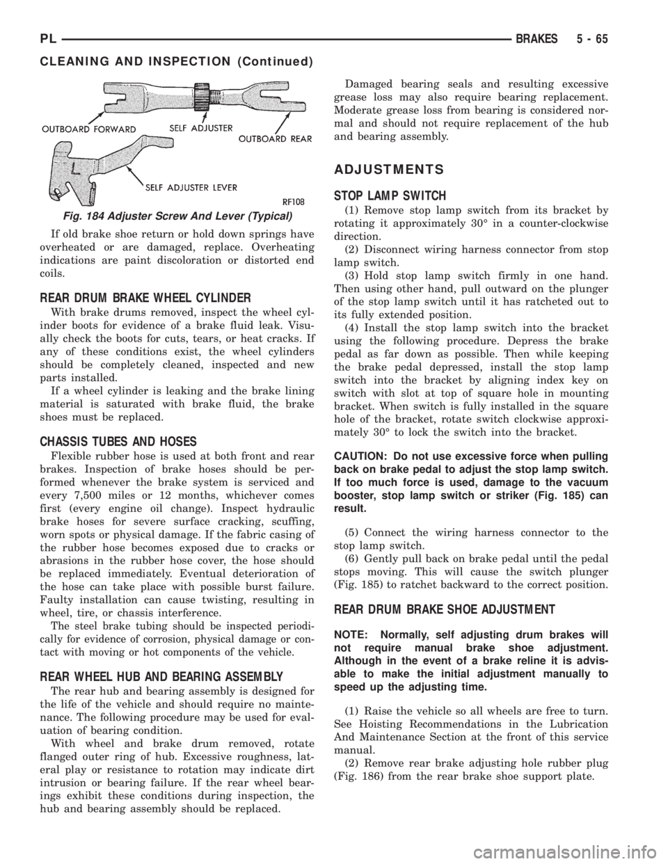
Fig. 184 Adjuster Screw And Lever (Typical)
PLBRAKES 5 - 65
CLEANING AND INSPECTION (Continued)
Page 156 of 1200
cally cleared from the CAB memory after the identi-
cal fault has not been seen during the next 255 key
cycles of vehicle operation.
CONTROLLER ANTILOCK BRAKE INPUTS
²Four wheel speed sensors.
²Stop lamp switch.
²Ignition switch.
²System relay voltage.
²Ground.
²Diagnostics Communications (CCD)
CONTROLLER ANTILOCK BRAKE OUTPUTS
²ABS warning lamp actuation.
²Diagnostic communication. (CCD)
ABS WARNING LAMP (YELLOW)
The ABS system uses a yellow colored ABS Warn-
ing Lamp. The ABS warning lamp is located on the
lower left side of the instrument pane. The purpose
of the warning lamp is discussed in detail below.
The ABS warning lamp will turn on when the CAB
detects a condition which results in a shutdown of
ABS function. When the ignition key is turned to the
on position, the ABS Warning Lamp is on until the
CAB completes its self tests and turns the lamp off
(approximately 4 seconds after the ignition switch is
turned on). Under most conditions, when the ABS
warning lamp is on, only the ABS function of the
brake system is affected. The standard brake system
and the ability to stop the car will not be affected
when only the ABS warning lamp is on.
The ABS warning lamp is controlled by the CAB.
The CAB turns on the yellow ABS warning lamp by
grounding the circuit.
HYDRAULIC CIRCUITS AND VALVE OPERATION
Through the following operation descriptions the
function of the various hydraulic control valves in the
ABS will be described. The fluid control valves men-
tioned below, control the flow of pressurized brake
fluid to the wheel brakes during the different modes
of ABS braking.
For explanation purposes, all wheel speed sensors
except the right front are sending the same wheel
speed information. The following diagrams show only
the right front wheel in a antilock braking condition.
NORMAL BRAKING HYDRAULIC CIRCUIT AND
SOLENOID VALVE FUNCTION
This condition is the normal operation of the vehi-
cles base brake hydraulic system. The hydraulic sys-
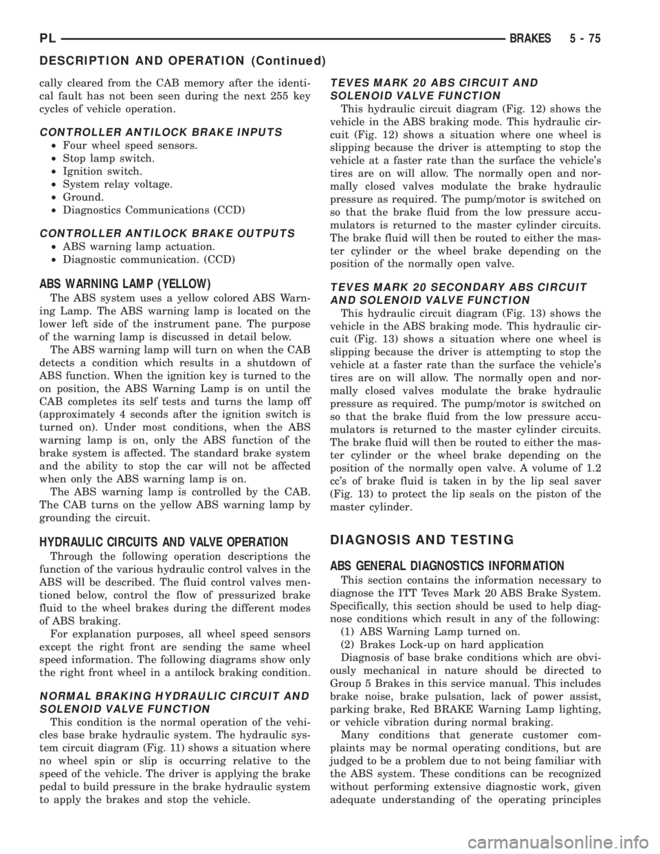
tem circuit diagram (Fig. 11) shows a situation where
no wheel spin or slip is occurring relative to the
speed of the vehicle. The driver is applying the brake
pedal to build pressure in the brake hydraulic system
to apply the brakes and stop the vehicle.
TEVES MARK 20 ABS CIRCUIT AND
SOLENOID VALVE FUNCTION
This hydraulic circuit diagram (Fig. 12) shows the
vehicle in the ABS braking mode. This hydraulic cir-
cuit (Fig. 12) shows a situation where one wheel is
slipping because the driver is attempting to stop the
vehicle at a faster rate than the surface the vehicle's
tires are on will allow. The normally open and nor-
mally closed valves modulate the brake hydraulic
pressure as required. The pump/motor is switched on
so that the brake fluid from the low pressure accu-
mulators is returned to the master cylinder circuits.
The brake fluid will then be routed to either the mas-
ter cylinder or the wheel brake depending on the
position of the normally open valve.
TEVES MARK 20 SECONDARY ABS CIRCUIT
AND SOLENOID VALVE FUNCTION
This hydraulic circuit diagram (Fig. 13) shows the
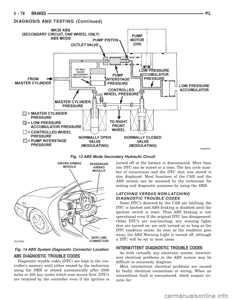
vehicle in the ABS braking mode. This hydraulic cir-
cuit (Fig. 13) shows a situation where one wheel is
slipping because the driver is attempting to stop the
vehicle at a faster rate than the surface the vehicle's
tires are on will allow. The normally open and nor-
mally closed valves modulate the brake hydraulic
pressure as required. The pump/motor is switched on
so that the brake fluid from the low pressure accu-
mulators is returned to the master cylinder circuits.
The brake fluid will then be routed to either the mas-
ter cylinder or the wheel brake depending on the
position of the normally open valve. A volume of 1.2
cc's of brake fluid is taken in by the lip seal saver
(Fig. 13) to protect the lip seals on the piston of the
master cylinder.
DIAGNOSIS AND TESTING
ABS GENERAL DIAGNOSTICS INFORMATION
This section contains the information necessary to
diagnose the ITT Teves Mark 20 ABS Brake System.
Specifically, this section should be used to help diag-
nose conditions which result in any of the following:
(1) ABS Warning Lamp turned on.
(2) Brakes Lock-up on hard application
Diagnosis of base brake conditions which are obvi-
ously mechanical in nature should be directed to
Group 5 Brakes in this service manual. This includes
brake noise, brake pulsation, lack of power assist,
parking brake, Red BRAKE Warning Lamp lighting,
or vehicle vibration during normal braking.
Many conditions that generate customer com-
plaints may be normal operating conditions, but are
judged to be a problem due to not being familiar with
the ABS system. These conditions can be recognized
without performing extensive diagnostic work, given
adequate understanding of the operating principles
PLBRAKES 5 - 75
DESCRIPTION AND OPERATION (Continued)
Page 159 of 1200
ABS DIAGNOSTIC TROUBLE CODES
Diagnostic trouble codes (DTC) are kept in the con-
troller's memory until either erased by the technician
using the DRB or erased automatically after 3500
miles or 255 key cycles which ever occurs first. DTC's
are retained by the controller even if the ignition isturned off or the battery is disconnected. More than
one DTC can be stored at a time. The key cycle num-
ber of occurrences and the DTC that was stored is
also displayed. Most functions of the CAB and the
ABS system can be accessed by the technician for
testing and diagnostic purposes by using the DRB.
LATCHING VERSUS NON-LATCHING
DIAGNOSTIC TROUBLE CODES
Some DTC's detected by the CAB are latching; the
DTC is latched and ABS braking is disabled until the
ignition switch is reset. Thus ABS braking is non
operational even if the original DTC has disappeared.
Other DTC's are non-latching; any warning lights
that are turned on, are only turned on as long as the
DTC condition exists. As soon as the condition goes
away, the ABS Warning Light is turned off, although
a DTC will be set in most cases.
INTERMITTENT DIAGNOSTIC TROUBLE CODES
As with virtually any electronic system, intermit-
tent electrical problems in the ABS system may be
difficult to accurately diagnose.
Most intermittent electrical problems are caused
by faulty electrical connections or wiring. When an
intermittent fault is encountered, check suspect cir-
cuits for:
Fig. 13 ABS Mode Secondary Hydraulic Circuit
Fig. 14 ABS System Diagnostic Connector Location
5 - 78 BRAKESPL
DIAGNOSIS AND TESTING (Continued)
Page 160 of 1200
A visual inspection for loose, disconnected, or mis-
routed wires should be done before attempting to
diagnose or service the ITT Teves Mark 20 antilock
brake system. A visual inspection will eliminate
unnecessary testing and diagnostics time. A thorough
visual inspection will include the following compo-
nents and areas of the vehicle.
(1) Inspect fuses in the power distribution center
(PDC) and the wiring junction block. Verify that all
fuses are fully inserted into the PDC and wring junc-
tion block. A label on the underside of the PDC cover
identifies the locations of the ABS fuses in the PDC.
(2) Inspect the 25-way electrical connector at the
CAB for damage, spread or backed-out wiring termi-
nals. Verify that the 25-way connector is fully
inserted in the socket on the CAB. Be sure that wires
are not stretched tight or pulled out of the connector.
(3) Verify that all the wheel speed sensor connec-
tions are secure.
(4) Poor mating of connector halves or terminals
not fully seated in the connector body.
(5) Improperly formed or damaged terminals. All
connector terminals in a suspect circuit should be
carefully reformed to increase contact tension.
(6) Poor terminal to wire connection. This requires
removing the terminal from the connector body to
inspect.
(7) Pin presence in the connector assembly
(8) Proper ground connections. Check all ground
connections for signs of corrosion, tight fasteners, or
other potential defects. Refer to wiring diagram man-
ual for ground locations.
(9) Problems with main power sources of the vehi-
cle. Inspect battery, generator, ignition circuits and
other related relays and fuses.
(10) If a visual check does not find the cause of the
problem, operate the car in an attempt to duplicate
the condition and record the trouble code.
(11) Most failures of the ABS system will disable
ABS function for the entire ignition cycle even if the
fault clears before key-off. There are some failure
conditions, however, which will allow ABS operation
to resume during the ignition cycle in which a failure
occurred if the failure conditions are no longer
present. The following conditions may result in inter-
mittent illumination of the ABS Warning Lamp. All
other failures will cause the lamp to remain on until
the ignition switch is turned off. Circuits involving
these inputs to the CAB should be investigated if a
complaint of intermittent warning system operation
is encountered.
(12) Low system voltage. If Low System Voltage is
detected by the CAB, the CAB will turn on the ABS
Warning Lamp until normal system voltage is
achieved. Once normal voltage is seen at the CAB,
normal operation resumes.(13) High system voltage. If high system voltage is
detected by the CAB, the CAB will turn on the
Amber ABS Warning Lamp until normal system volt-
age is achieved. Once normal voltage is again
detected by the CAB, normal ABS operation resumes.
(14) Additionally, any condition which results in
interruption of electrical current to the CAB or mod-
ulator assembly may cause the ABS Warning Lamp
to turn on intermittently.
(15) The body controller can turn on the (yellow)
ABS warning lamp if CCD communication between
the body controller and the CAB is interupted.
TONEWHEEL INSPECTION
CAUTION: The tone wheels used on this vehicle
equipped with the Teves Mark 20 Antilock Brake
System are different then those used on past mod-
els of this vehicle equipped with antilock brakes.
Reduced braking performance will result if this part
is used on earlier model vehicles and an accident
could result. Do not use on pre-1998 model year
vehicles.
Carefully inspect tonewheel at the suspected faulty
wheel speed sensor for missing, chipped or broken
teeth, this can cause erratic speed sensor signals.
Tonewheels should show no evidence of contact
with the wheel speed sensors. If contact was made,
determine cause and correct before replacing the
wheel speed sensor.
Excessive runout of the tonewheel can cause
erratic wheel speed sensor signals. Refer to Tone-
wheel Runout in the Specification Section in this sec-
tion of the service manual for the tonewheel runout
specification. Replace drive shaft assembly or rear
hub/bearing assembly if tonewheel runout exceeds
the specification.
Inspect tonewheels for looseness on their mounting
surfaces. Tonewheels are pressed onto their mounting
surfaces and should not rotate independently from
the mounting surface.
Check the wheel speed sensor head alignment to
the tone wheel. Also check the gap between the speed
sensor head and the tone wheel to ensure it is at
specification. Refer to Wheel Speed Sensor Clearance
in the Specification Section in this section of the ser-
vice manual.
PROPORTIONING VALVE
CAUTION: Proportioning valves should never be
disassembled.
If premature rear wheel skid occurs on a hard
brake application, it could be an indication that a
PLBRAKES 5 - 79
DIAGNOSIS AND TESTING (Continued)
Page 161 of 1200
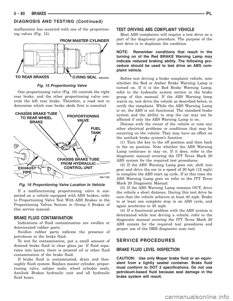
malfunction has occurred with one of the proportion-
ing valves (Fig. 15).
One proportioning valve (Fig. 16) controls the right
rear brake, and the other proportioning valve con-
trols the left rear brake. Therefore, a road test to
determine which rear brake skids first is essential.
If a malfunctioning proportioning valve is sus-
pected on a vehicle equipped with ABS brakes, refer
to Proportioning Valve Test With ABS Brakes in the
Proportioning Valves Section in Group 5 Brakes of
this service manual.
BRAKE FLUID CONTAMINATION
Indications of fluid contamination are swollen or
deteriorated rubber parts.
Swollen rubber parts indicate the presence of
petroleum in the brake fluid.
To test for contamination, put a small amount of
drained brake fluid in clear glass jar. If fluid sepa-
rates into layers, there is mineral oil or other fluid
contamination of the brake fluid.
If brake fluid is contaminated, drain and thor-
oughly flush system. Replace master cylinder, propor-
tioning valve, caliper seals, wheel cylinder seals,
Antilock Brakes hydraulic unit and all hydraulic
fluid hoses.
TEST DRIVING ABS COMPLAINT VEHICLE
Most ABS complaints will require a test drive as a
part of the diagnostic procedure. The purpose of the
test drive is to duplicate the condition.
NOTE: Remember conditions that result in the
turning on of the Red BRAKE Warning Lamp may
indicate reduced braking ability. The following pro-
cedure should be used to test drive an ABS com-
plaint vehicle.
Before test driving a brake complaint vehicle, note
whether the Red or Amber Brake Warning Lamp is
turned on. If it is the Red Brake Warning Lamp,
refer to the hydraulic system section in the brake
group of this manual. If the ABS Warning lamp
was/is on, test drive the vehicle as described below, to
verify the complaint. While the ABS Warning Lamp
is on, the ABS is not functional. The standard brake
system and the ability to stop the car may not be
affected if only the ABS Warning Lamp is on.
Discuss with the owner of the vehicle or note any
other electrical problems or conditions that may be
occurring on the vehicle. They may have an effect on
the antilock brake system's function.
(1) Turn the key to the off position and then back
to the on position. Note whether the ABS Warning
Lamp continues to stay on. If it does, refer to the
diagnostic manual covering the ITT Teves Mark 20
ABS system for the required test procedures.
(2) If the ABS Warning Lamp goes out, shift into
gear and drive the car to a speed of 20 kph (12 mph)
to complete the ABS start up cycle. If at this time the
ABS Warning Lamp goes on refer to the ITT Teves
Mark 20 Diagnostic Manual.
(3) If the ABS Warning Lamp remains OUT, drive
the vehicle a short distance. During this test drive be
sure that the vehicle achieves at least 40 mph. Brake
to at least one complete stop in an ABS cycle, and
again accelerate to 25 mph.
(4) If a functional problem with the ABS system is
determined while test driving a vehicle, refer to the
diagnostic manual covering the ITT Teves Mark 20
ABS system for the required test procedures and
proper use of the DRB diagnostic scan tool.
SERVICE PROCEDURES
BRAKE FLUID LEVEL INSPECTION
CAUTION: Use only Mopar brake fluid or an equiv-
alent from a tightly sealed container. Brake fluid
must conform to DOT 3 specifications. Do not use
petroleum-based fluid because seal damage in the
brake system will result.
Fig. 15 Proportioning Valve
Fig. 16 Proportioning Valve Location In Vehicle
5 - 80 BRAKESPL
DIAGNOSIS AND TESTING (Continued)
Page 174 of 1200
CLUTCH PEDAL POSITION
SWITCH±MECHANICAL TEST
With the park brake set and the vehicleIN NEU-
TRAL,turn the key to the start position. The vehicle
should not crank. If the vehicle cranks, the switch is
defective (shorted out) and must be replaced. If the
vehicle does not crank, proceed to the next step.
WARNING: BEFORE PERFORMING THIS STEP, BE
SURE THAT THE AREA IN FRONT OF THE VEHICLE
IS CLEAR OF OBSTRUCTIONS AND PEOPLE. VEHI-
CLE MAY MOVE WHEN PERFORMING THIS TEST.
With the park brake set and the vehicleIN GEAR,
turn the key to the start position and hold it there.
Slowly depress the clutch pedal and feel for any
vehicle motion when the starter is energized. If there
is no motion, the switch is working properly.
If motion is felt, check to see if the switch is mak-
ing contact when the pedal is between 25 mm (1.0
in.) and 6 mm (0.25 in.) from the floor. If this condi-
tion is met, then the problem is either the clutch orthe self-adjusting cable (See ªClutch Will Not Disen-
gage Properlyº). If this condition is not met, then the
switch mounting tab on the brake bracket is bent,
and the brake bracket must be replaced.
If vehicle will not crank, even with clutch pedal
pressed to the floor, refer to ªService Diagnosis-
Clutch Pedal Position Switchº chart in this section.
CLUTCH DIAGNOSIS
Problem diagnosis will generally require a road
test to determine the type of fault. Component
inspection will then determine the problem after road
testing.
Drive the vehicle at normal speeds during road
test. Shift the transaxle through all gear ranges and
observe clutch action. If chatter, grab, slip, or
improper release is experienced, remove and inspect
the clutch components. If the problem is noise or
hard shifting, further diagnosis may be needed. The
transaxle or other driveline components may actually
be at fault.
SERVICE DIAGNOSISÐCLUTCH GRAB/CHATTER
CONDITION POSSIBLE CAUSES CORRECTION
CLUTCH DISC FACING
COVERED WITH OIL OR
GREASEOil leak at engine rear main or
transaxle input shaft sealCorrect leak and replace w/modular clutch
assembly
Too much grease applied to splines
of disc and input shaftApply lighter coating of grease to splines
NO FAULT FOUND WITH
CLUTCH
COMPONENTSProblem actually related to
suspension or driveline componentFurther diagnosis required. Check
engine/transmission mounts, suspension
attaching parts and other driveline
components as needed.
Engine related problems Check EFI and ignition systems
PARTIAL ENGAGEMENT
OF CLUTCH DISCClutch cover, spring, or release
fingers bent, distorted (rough
handling, improper assembly)Replace w/modular clutch assembly
Clutch disc damaged or distorted Replace w/modular clutch assembly
Clutch misalignment Check alignment and runout of flywheel,
disc, or cover. Check clutch housing to
engine dowels and dowel holes for damage.
Correct as necessary.
PLCLUTCH 6 - 3
DIAGNOSIS AND TESTING (Continued)
Page 218 of 1200
BATTERY
CONTENTS
page page
GENERAL INFORMATION
INTRODUCTION......................... 1
DESCRIPTION AND OPERATION
BATTERY IGNITION OFF DRAW (IOD)........ 1
CHARGING TIME REQUIRED............... 1
DIAGNOSIS AND TESTING
BATTERY BUILT-IN TEST INDICATOR........ 2
BATTERY IGNITION OFF DRAW (IOD)........ 3
BATTERY LOAD TEST..................... 5
BATTERY OPEN CIRCUIT VOLTAGE TEST..... 6
BATTERY TEMPERATURE SENSOR.......... 6
SERVICE PROCEDURES
BATTERY CHARGING..................... 6CHARGING COMPLETELY DISCHARGED
BATTERY............................. 7
VISUAL INSPECTION..................... 7
REMOVAL AND INSTALLATION
BATTERY TRAY.......................... 9
BATTERY............................... 8
FRESH AIR INLET TUBE REMOVAL.......... 9
SPECIFICATIONS
BATTERY SPECIFICATIONS............... 10
TORQUE.............................. 10
GENERAL INFORMATION
INTRODUCTION
The battery stores, stabilizes, and delivers electri-
cal current to operate various electrical systems in
the vehicle. The determination of whether a battery
is good or bad is made by its ability to accept a
charge. It also must supply high-amperage current
for a long enough period to be able to start the vehi-
cle. The capability of the battery to store electrical
current comes from a chemical reaction. This reac-
tion takes place between the sulfuric acid solution
(electrolyte) and the lead +/- plates in each cell of the
battery. As the battery discharges, the plates react
with the acid from the electrolyte. When the charging
system charges the battery, the water is converted to
sulfuric acid in the battery. The concentration of acid
in the electrolyte is measured as specific gravity
using a hydrometer. The original equipment (OE)
battery is equipped with a hydrometer (test indica-
tor) built into the battery cover. The specific gravity
indicates the battery's state-of-charge. The OE bat-
tery is sealed and water cannot be added.
The battery is vented to release gases that are cre-
ated when the battery is being charged and dis-
charged. The battery top, posts, and terminals should
be cleaned when other under hood maintenance is
performed.
When the electrolyte level is below the top of the
plates, Yellow/Clear in the test Indicator, the battery
must be replaced. The battery must be completely
charged, and the battery top, posts, and cable clampsmust be cleaned before diagnostic procedures are per-
formed.DESCRIPTION AND OPERATION
BATTERY IGNITION OFF DRAW (IOD)
A completely normal vehicle will have a small
amount of current drain on the battery with the key
out of the ignition. It can range from 4 to 10 milli-
amperes after all the modules time out. If a vehicle
will not be operated for approximately a 20 days, the
IOD fuse should be disconnected to minimize the
vehicle electrical drain on the battery. The IOD fuse
is located in the Power Distribution Center (PDC).
Refer to the PDC to locate the cover proper fuse.
CHARGING TIME REQUIRED
WARNING: NEVER EXCEED 20 AMPS WHEN
CHARGING A COLD -1ÉC (30ÉF) BATTERY. PER-
SONAL INJURY MAY RESULT.
The time required to charge a battery will vary
depending upon the following factors.
SIZE OF BATTERY
A completely discharged large heavy-duty battery
may require more recharging time than a completely
discharged small capacity battery. Refer to Battery
Charging Timetable for proper charging times.
PLBATTERY 8A - 1
Page 220 of 1200
NOTE: BLACK OR DARK=0to75%state-of-charge
The battery is INADEQUATELY charged and must
be charged until green dot is visible, (12.4 volts or
greater) before the battery is tested or returned to
use. Refer to Causes of Battery Discharging in this
Group for more information.
NOTE: CLEAR COLOR = Replace Battery
WARNING: DO NOT CHARGE, ASSIST BOOST,
LOAD TEST, OR ADD WATER TO THE BATTERY
WHEN CLEAR COLOR DOT IS VISIBLE. PERSONAL
INJURY MAY OCCUR.
A clear color dot shows electrolyte level in battery
is below the test indicator (Fig. 1). Water cannot be
added to a maintenance free battery. The battery
must be replaced. A low electrolyte level may be
caused by an over charging condition. Refer to Gen-
erator Test Procedures on Vehicle.
CAUSES OF BATTERY DISCHARGING
It is normal to have a small 5 to 25 milliamperes
continuous electrical draw from the battery. This
draw will take place with the ignition in the OFF
position, and the courtesy, dome, storage compart-
ments, and engine compartment lights OFF. The con-
tinuous draw is due to various electronic features or
accessories that require electrical current with the
ignition OFF to function properly. When a vehicle is
not used over an extended period of approximately 20
days the IOD fuse should be pulled. The fuse is
located in the power distribution center. removal of
this fuse will reduce the level of battery discharge.
Refer to the Battery Diagnosis and Testing Table for
proper diagnosis.
ABNORMAL BATTERY DISCHARGING
²Corroded battery posts, cables or terminals.
²Loose or worn generator drive belt.
²Electrical loads that exceed the output of the
charging system due to equipment or accessories
installed after delivery.
²Slow driving speeds in heavy traffic conditions
or prolonged idling with high-amperage electrical
systems in use.
²Defective electrical circuit or component causing
excess Ignition Off Draw (IOD). Refer to Battery
Ignition Off Draw (IOD).
²Defective charging system.
²Defective battery.
BATTERY IGNITION OFF DRAW (IOD)
High current draw on the battery with the ignition
OFF will discharge a battery. After a dead battery is
recharged, the vehicle ignition off draw (IOD) shouldbe checked. To determine if a high current draw con-
dition exists first check the vehicle with a test lamp.
(1) Verify that all electrical accessories are OFF.
²Remove key from ignition switch
²Turn off all lights
²Trunk lid is closed
²Engine compartment hood lamp is disconnected
or lamp removed
²Glove box door is closed
²Sun visor vanity lights are OFF
²All doors are closed
²Allow the ignition key lamp system to time out
in approximately 30 seconds, if equipped.
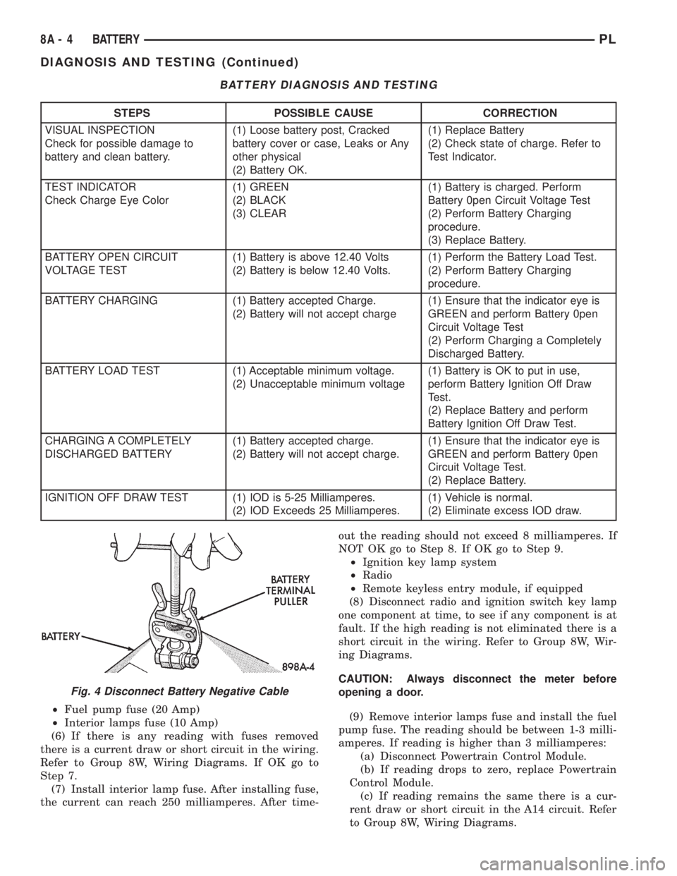
(2) Disconnect battery negative cable (Fig. 4).
(3) Connect a 12 Volt test lamp, with a cold resis-
tance of 5-7 ohms, between the battery negative cable
clamp and the negative post (Fig. 5). If test lamp
goes out system is OK. If test lamp lights and stays
ON, go to Test Lamp Stays ON procedure.
TEST LAMP STAYS ON
There is either a short circuit or a fault in an elec-
tronic module. Two fuses in the Power Distribution
Center (PDC) feed the modules with ignition off
draw.
²Interior lamps fuse (10 Amp) (IOD) PDC.
²Fuel pump fuse (20 Amp) in PDC
(1) Remove interior lamp and fuel pump fuses. By
removing these fuses all ignition off draw from the
vehicle electronics will be disconnected. The test
lamp should go out. If test lamp goes out go to Step
2. If test lamp does not go out there is a current
draw or short circuit. Refer to Group 8W, Wiring Dia-
grams.
(2) Install the fuel pump fuse. If test lamp lights,
there is a current draw or short circuit in the A14
wiring circuit feed.
(a) Disconnect Powertrain Control Module.
(b) If test lamp goes out, replace Powertrain
Control Module.
(c) If test lamp does not go out, there is a cur-
rent draw or short circuit in the A14 circuit feed.
Refer to Group 8W, Wiring Diagrams.
(3) Install the interior lamp fuse. If test lamp
lights, there is a current draw or short circuit in the
M01 circuit. Refer to Group 8W, Wiring Diagrams. If
test lamp stays out, go to Step 4
(4) Use a multi-meter that has at least a range of
200 milliamperes. Install meter between the battery
negative cable and battery negative post (Fig. 6).
Carefully remove the test lamp without disconnecting
the meter. After all modules time-out the total vehi-
cle IOD should be less than 10 milliamperes. If igni-
tion off draw is more than 10 milliamperes go to Step
5.
(5) Remove both fuses from the Power Distribution
Center:
PLBATTERY 8A - 3
DIAGNOSIS AND TESTING (Continued)
Page 221 of 1200
²Fuel pump fuse (20 Amp)
²Interior lamps fuse (10 Amp)
(6) If there is any reading with fuses removed
there is a current draw or short circuit in the wiring.
Refer to Group 8W, Wiring Diagrams. If OK go to
Step 7.
(7) Install interior lamp fuse. After installing fuse,
the current can reach 250 milliamperes. After time-out the reading should not exceed 8 milliamperes. If
NOT OK go to Step 8. If OK go to Step 9.
²Ignition key lamp system
²Radio
²Remote keyless entry module, if equipped
(8) Disconnect radio and ignition switch key lamp
one component at time, to see if any component is at
fault. If the high reading is not eliminated there is a
short circuit in the wiring. Refer to Group 8W, Wir-
ing Diagrams.
CAUTION: Always disconnect the meter before
opening a door.
(9) Remove interior lamps fuse and install the fuel
pump fuse. The reading should be between 1-3 milli-
amperes. If reading is higher than 3 milliamperes:
(a) Disconnect Powertrain Control Module.
(b) If reading drops to zero, replace Powertrain
Control Module.
(c) If reading remains the same there is a cur-
rent draw or short circuit in the A14 circuit. Refer
to Group 8W, Wiring Diagrams.
BATTERY DIAGNOSIS AND TESTING
STEPS POSSIBLE CAUSE CORRECTION
VISUAL INSPECTION
Check for possible damage to
battery and clean battery.(1) Loose battery post, Cracked
battery cover or case, Leaks or Any
other physical
(2) Battery OK.(1) Replace Battery
(2) Check state of charge. Refer to
Test Indicator.
TEST INDICATOR
Check Charge Eye Color(1) GREEN
(2) BLACK
(3) CLEAR(1) Battery is charged. Perform
Battery 0pen Circuit Voltage Test
(2) Perform Battery Charging
procedure.
(3) Replace Battery.
BATTERY OPEN CIRCUIT
VOLTAGE TEST(1) Battery is above 12.40 Volts
(2) Battery is below 12.40 Volts.(1) Perform the Battery Load Test.
(2) Perform Battery Charging
procedure.
BATTERY CHARGING (1) Battery accepted Charge.
(2) Battery will not accept charge(1) Ensure that the indicator eye is
GREEN and perform Battery 0pen
Circuit Voltage Test
(2) Perform Charging a Completely
Discharged Battery.
BATTERY LOAD TEST (1) Acceptable minimum voltage.
(2) Unacceptable minimum voltage(1) Battery is OK to put in use,
perform Battery Ignition Off Draw
Test.
(2) Replace Battery and perform
Battery Ignition Off Draw Test.
CHARGING A COMPLETELY
DISCHARGED BATTERY(1) Battery accepted charge.
(2) Battery will not accept charge.(1) Ensure that the indicator eye is
GREEN and perform Battery 0pen
Circuit Voltage Test.
(2) Replace Battery.
IGNITION OFF DRAW TEST (1) IOD is 5-25 Milliamperes.
(2) IOD Exceeds 25 Milliamperes.(1) Vehicle is normal.
(2) Eliminate excess IOD draw.
Fig. 4 Disconnect Battery Negative Cable
8A - 4 BATTERYPL
DIAGNOSIS AND TESTING (Continued)