Inside DODGE NEON 1999 Service Repair Manual
[x] Cancel search | Manufacturer: DODGE, Model Year: 1999, Model line: NEON, Model: DODGE NEON 1999Pages: 1200, PDF Size: 35.29 MB
Page 75 of 1200
(5) Slide sealing boot off interconnecting shaft.
(6) Thoroughly clean and inspect spider assembly,
tripod joint housing, and interconnecting shaft for
any signs of excessive wear.If any parts show
signs of excessive wear, the driveshaft assembly
will require replacement. Component parts of
these driveshaft assemblies are not serviceable.
INSTALLATION
NOTE: The inner tripod joint sealing boots are
made from two different types of material. High±t-
emperature applications use silicone rubber
whereas standard temperature applications use
Hytrel plastic. The silicone sealing boots are soft
and pliable. The Hytrel sealing boots are stiff and
rigid. The replacement sealing boot MUST BE the
same type of material as the sealing boot that was
removed.
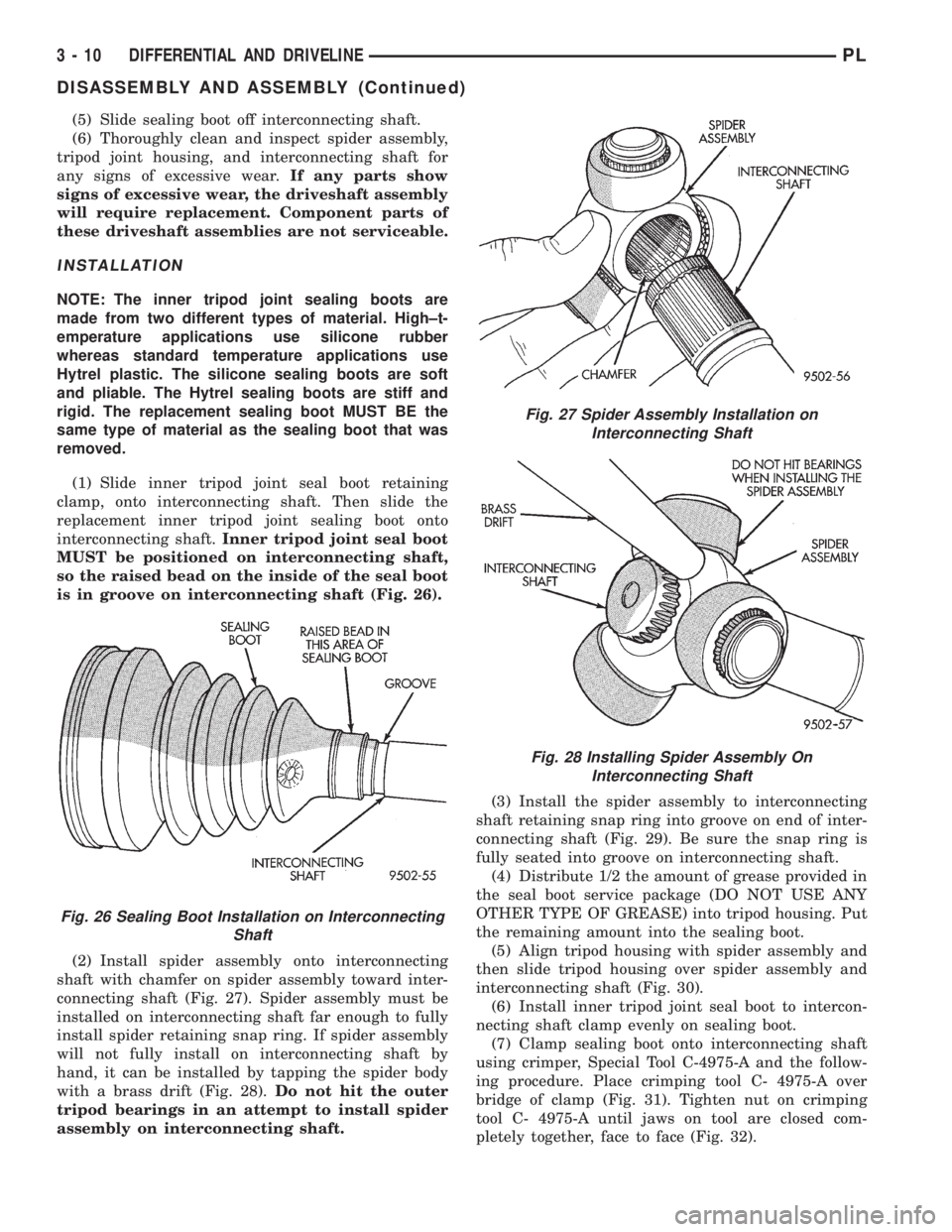
(1) Slide inner tripod joint seal boot retaining
clamp, onto interconnecting shaft. Then slide the
replacement inner tripod joint sealing boot onto
interconnecting shaft.Inner tripod joint seal boot
MUST be positioned on interconnecting shaft,
so the raised bead on the inside of the seal boot
is in groove on interconnecting shaft (Fig. 26).
(2) Install spider assembly onto interconnecting
shaft with chamfer on spider assembly toward inter-
connecting shaft (Fig. 27). Spider assembly must be
installed on interconnecting shaft far enough to fully
install spider retaining snap ring. If spider assembly
will not fully install on interconnecting shaft by
hand, it can be installed by tapping the spider body
with a brass drift (Fig. 28).Do not hit the outer
tripod bearings in an attempt to install spider
assembly on interconnecting shaft.(3) Install the spider assembly to interconnecting
shaft retaining snap ring into groove on end of inter-
connecting shaft (Fig. 29). Be sure the snap ring is
fully seated into groove on interconnecting shaft.
(4) Distribute 1/2 the amount of grease provided in
the seal boot service package (DO NOT USE ANY
OTHER TYPE OF GREASE) into tripod housing. Put
the remaining amount into the sealing boot.
(5) Align tripod housing with spider assembly and
then slide tripod housing over spider assembly and
interconnecting shaft (Fig. 30).
(6) Install inner tripod joint seal boot to intercon-
necting shaft clamp evenly on sealing boot.
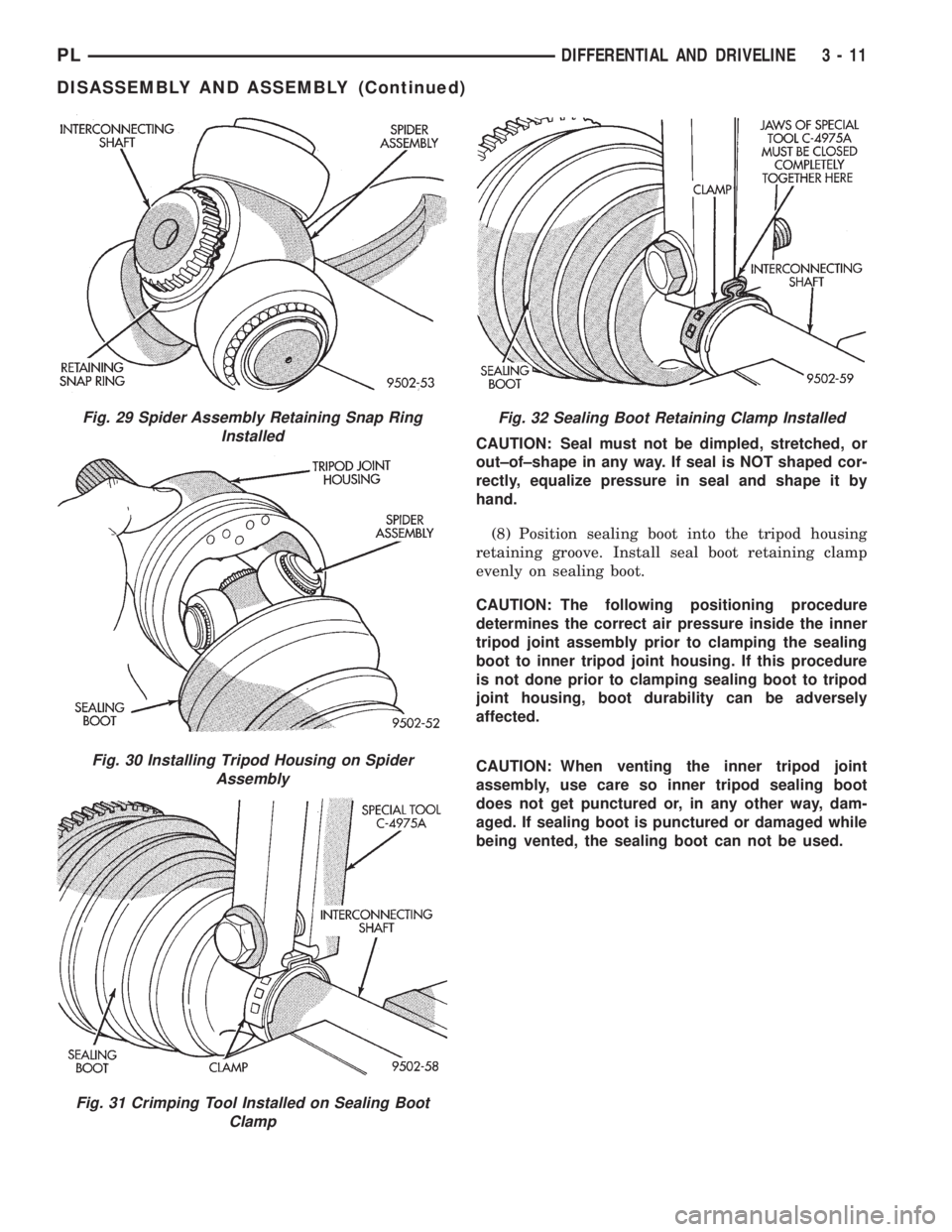
(7) Clamp sealing boot onto interconnecting shaft
using crimper, Special Tool C-4975-A and the follow-
ing procedure. Place crimping tool C- 4975-A over
bridge of clamp (Fig. 31). Tighten nut on crimping
tool C- 4975-A until jaws on tool are closed com-
pletely together, face to face (Fig. 32).
Fig. 26 Sealing Boot Installation on Interconnecting
Shaft
Fig. 27 Spider Assembly Installation on
Interconnecting Shaft
Fig. 28 Installing Spider Assembly On
Interconnecting Shaft
3 - 10 DIFFERENTIAL AND DRIVELINEPL
DISASSEMBLY AND ASSEMBLY (Continued)
Page 76 of 1200
CAUTION: Seal must not be dimpled, stretched, or
out±of±shape in any way. If seal is NOT shaped cor-
rectly, equalize pressure in seal and shape it by
hand.
(8) Position sealing boot into the tripod housing
retaining groove. Install seal boot retaining clamp
evenly on sealing boot.
CAUTION: The following positioning procedure
determines the correct air pressure inside the inner
tripod joint assembly prior to clamping the sealing
boot to inner tripod joint housing. If this procedure
is not done prior to clamping sealing boot to tripod
joint housing, boot durability can be adversely
affected.
CAUTION: When venting the inner tripod joint
assembly, use care so inner tripod sealing boot
does not get punctured or, in any other way, dam-
aged. If sealing boot is punctured or damaged while
being vented, the sealing boot can not be used.
Fig. 29 Spider Assembly Retaining Snap Ring
Installed
Fig. 30 Installing Tripod Housing on Spider
Assembly
Fig. 31 Crimping Tool Installed on Sealing Boot
Clamp
Fig. 32 Sealing Boot Retaining Clamp Installed
PLDIFFERENTIAL AND DRIVELINE 3 - 11
DISASSEMBLY AND ASSEMBLY (Continued)
Page 79 of 1200
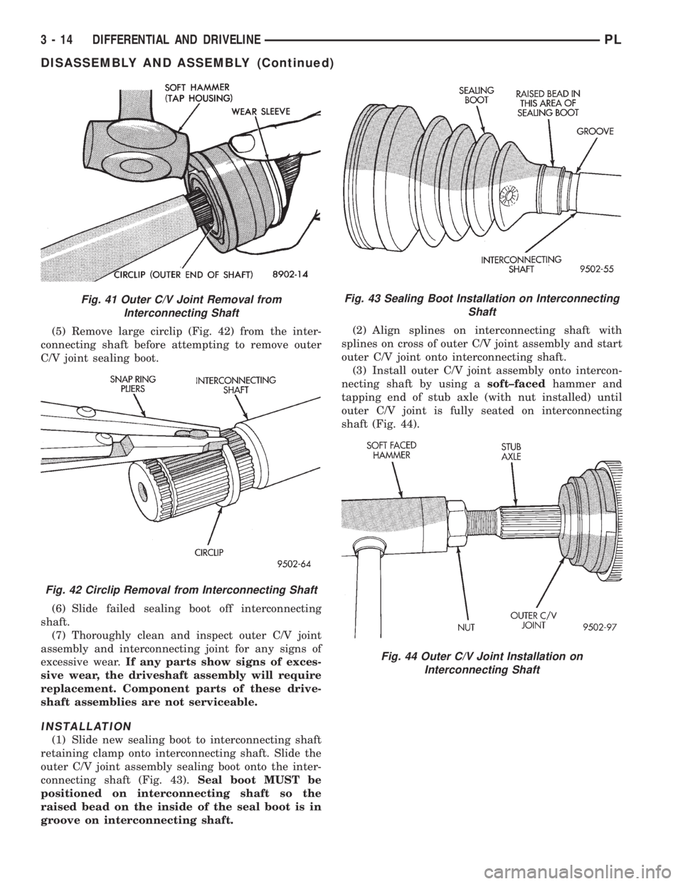
(5) Remove large circlip (Fig. 42) from the inter-
connecting shaft before attempting to remove outer
C/V joint sealing boot.
(6) Slide failed sealing boot off interconnecting
shaft.
(7) Thoroughly clean and inspect outer C/V joint
assembly and interconnecting joint for any signs of
excessive wear.If any parts show signs of exces-
sive wear, the driveshaft assembly will require
replacement. Component parts of these drive-
shaft assemblies are not serviceable.
INSTALLATION
(1) Slide new sealing boot to interconnecting shaft
retaining clamp onto interconnecting shaft. Slide the
outer C/V joint assembly sealing boot onto the inter-
connecting shaft (Fig. 43).Seal boot MUST be
positioned on interconnecting shaft so the
raised bead on the inside of the seal boot is in
groove on interconnecting shaft.(2) Align splines on interconnecting shaft with
splines on cross of outer C/V joint assembly and start
outer C/V joint onto interconnecting shaft.
(3) Install outer C/V joint assembly onto intercon-
necting shaft by using asoft±facedhammer and
tapping end of stub axle (with nut installed) until
outer C/V joint is fully seated on interconnecting
shaft (Fig. 44).
Fig. 41 Outer C/V Joint Removal from
Interconnecting Shaft
Fig. 42 Circlip Removal from Interconnecting Shaft
Fig. 43 Sealing Boot Installation on Interconnecting
Shaft
Fig. 44 Outer C/V Joint Installation on
Interconnecting Shaft
3 - 14 DIFFERENTIAL AND DRIVELINEPL
DISASSEMBLY AND ASSEMBLY (Continued)
Page 85 of 1200
REAR DISC BRAKES
The rear disc brakes are similar to the front disc
brakes, however, there are several distinctive fea-
tures that require different service procedures. The
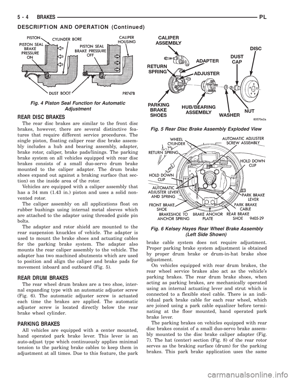
single piston, floating caliper rear disc brake assem-
bly includes a hub and bearing assembly, adapter,
brake rotor, caliper, brake pads/linings. The parking
brake system on all vehicles equipped with rear disc
brakes consists of a small duo-servo drum brake
mounted to the caliper adapter. The drum brake
shoes expand out against a braking surface (hat sec-
tion) on the inside area of the rotor.
Vehicles are equipped with a caliper assembly that
has a 34 mm (1.43 in.) piston and uses a solid non-
vented rotor.
The caliper assembly on all applications float on
rubber bushings using internal metal sleeves which
are attached to the adapter using threaded guide pin
bolts.
The adapter and rotor shield are mounted to the
rear suspension knuckles of vehicle. The adapter is
used to mount the brake shoes and actuating cables
for the parking brake system. The adapter also
mounts the rear caliper assembly to the vehicle. The
adapter has two machined abutments which are used
to position and align the caliper and brake pads for
movement inboard and outboard (Fig. 5).
REAR DRUM BRAKES
The rear wheel drum brakes are a two shoe, inter-
nal expanding type with an automatic adjuster screw
(Fig. 6). The automatic adjuster screw is actuated
each time the brakes are applied. The automatic
adjuster screw is located directly below the rear
brake wheel cylinder.
PARKING BRAKES
All vehicles are equipped with a center mounted,
hand operated park brake lever. This lever is an
auto-adjust type which continuously applies minimal
tension to the parking brake cables to keep them in
adjustment at all times. Due to this feature, the parkbrake cable system does not require adjustment.
Proper parking brake system adjustment is obtained
by proper drum brake or drum-in-hat brake shoe
adjustment.
On vehicles equipped with rear drum brakes, the
rear wheel service brakes also act as the vehicle's
parking brakes. The rear drum brake shoes, when
acting as parking brakes, are mechanically operated
using an internal actuating lever and strut which is
connected to a flexible steel cable. There is an indi-
vidual park brake cable for each rear wheel, which
are joined using a park cable equalizer before termi-
nating at the floor mounted, hand operated park
brake lever.
The parking brakes on vehicles equipped with rear
disc brakes consist of a small duo-servo brake assem-
bly mounted to the disc brake caliper adapter (Fig.
7). The hat (center) section (Fig. 8) of the rear rotor
serves as the braking surface (drum) for the parking
brakes. This park brake application uses the same
Fig. 4 Piston Seal Function for Automatic
Adjustment
Fig. 5 Rear Disc Brake Assembly Exploded View
Fig. 6 Kelsey Hayes Rear Wheel Brake Assembly
(Left Side Shown)
5 - 4 BRAKESPL
DESCRIPTION AND OPERATION (Continued)
Page 96 of 1200
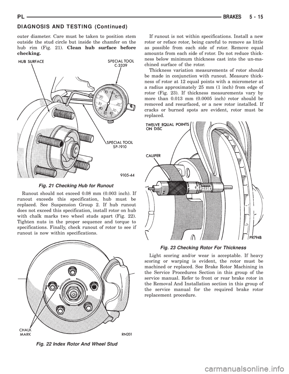
outer diameter. Care must be taken to position stem
outside the stud circle but inside the chamfer on the
hub rim (Fig. 21).Clean hub surface before
checking.
Runout should not exceed 0.08 mm (0.003 inch). If
runout exceeds this specification, hub must be
replaced. See Suspension Group 2. If hub runout
does not exceed this specification, install rotor on hub
with chalk marks two wheel studs apart (Fig. 22).
Tighten nuts in the proper sequence and torque to
specifications. Finally, check runout of rotor to see if
runout is now within specifications.If runout is not within specifications. Install a new
rotor or reface rotor, being careful to remove as little
as possible from each side of rotor. Remove equal
amounts from each side of rotor. Do not reduce thick-
ness below minimum thickness cast into the un-ma-
chined surface of the rotor.
Thickness variation measurements of rotor should
be made in conjunction with runout. Measure thick-
ness of rotor at 12 equal points with a micrometer at
a radius approximately 25 mm (1 inch) from edge of
rotor (Fig. 23). If thickness measurements vary by
more than 0.013 mm (0.0005 inch) rotor should be
removed and resurfaced, or a new rotor installed. If
cracks or burned spots are evident, rotor must be
replaced.
Light scoring and/or wear is acceptable. If heavy
scoring or warping is evident, the rotor must be
machined or replaced. See Brake Rotor Machining in
the Service Procedures Section in this group of the
service manual. Refer to front or rear brake rotor in
the Removal And Installation section in this group of
the service manual for the required brake rotor
replacement procedure.
Fig. 21 Checking Hub for Runout
Fig. 22 Index Rotor And Wheel Stud
Fig. 23 Checking Rotor For Thickness
PLBRAKES 5 - 15
DIAGNOSIS AND TESTING (Continued)
Page 106 of 1200
released position. Check the rear wheels of the vehi-
cle, they should rotate freely without dragging.
BRAKE TUBE REPAIR
Only double wall 4.75mm (3/16 in.) steel tubing
with Al-rich/ZN-AL alloy coating and the correct tube
nuts are to be used for replacement of a hydraulic
brake tube.
Care should be taken when repairing brake tubing,
to be sure the proper bending and flaring tools and
procedures are used, to avoid kinking. Do not route
the tubes against sharp edges, moving components or
into hot areas. All tubes should be properly attached
with recommended retaining clips.
Using Tubing Cutter, Special Tool C-3478-A or
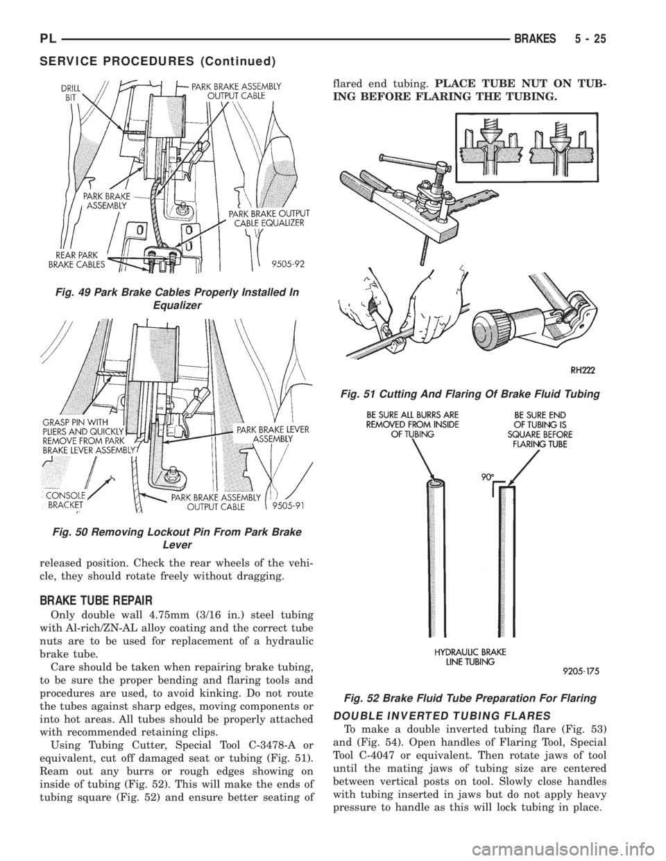
equivalent, cut off damaged seat or tubing (Fig. 51).
Ream out any burrs or rough edges showing on
inside of tubing (Fig. 52). This will make the ends of
tubing square (Fig. 52) and ensure better seating offlared end tubing.PLACE TUBE NUT ON TUB-
ING BEFORE FLARING THE TUBING.
DOUBLE INVERTED TUBING FLARES
To make a double inverted tubing flare (Fig. 53)
and (Fig. 54). Open handles of Flaring Tool, Special
Tool C-4047 or equivalent. Then rotate jaws of tool
until the mating jaws of tubing size are centered
between vertical posts on tool. Slowly close handles
with tubing inserted in jaws but do not apply heavy
pressure to handle as this will lock tubing in place.
Fig. 49 Park Brake Cables Properly Installed In
Equalizer
Fig. 50 Removing Lockout Pin From Park Brake
Lever
Fig. 51 Cutting And Flaring Of Brake Fluid Tubing
Fig. 52 Brake Fluid Tube Preparation For Flaring
PLBRAKES 5 - 25
SERVICE PROCEDURES (Continued)
Page 140 of 1200
Caliper Disassembly And Re-Assembly Procedures in
Disc Brake Caliper Service in this section of the ser-
vice manual.
Check the guide pin dust boots to determine if they
are in good condition. Replace if they are damaged,
dry, or found to be brittle. Refer to Guide Pin Bush-
ing Service in Disc Brake Caliper Service in this sec-
tion of the service manual.
CALIPER GUIDE PIN BUSHING SERVICE
The double pin caliper uses a sealed for life bush-
ing and sleeve assembly. If required this assembly
can be serviced using the following procedure.
REMOVING CALIPER GUIDE PIN BUSHINGS
(1) Remove caliper from brake rotor (See Brake
Shoe Removal). Hang caliper assembly on a wire
hook away from the brake rotor.
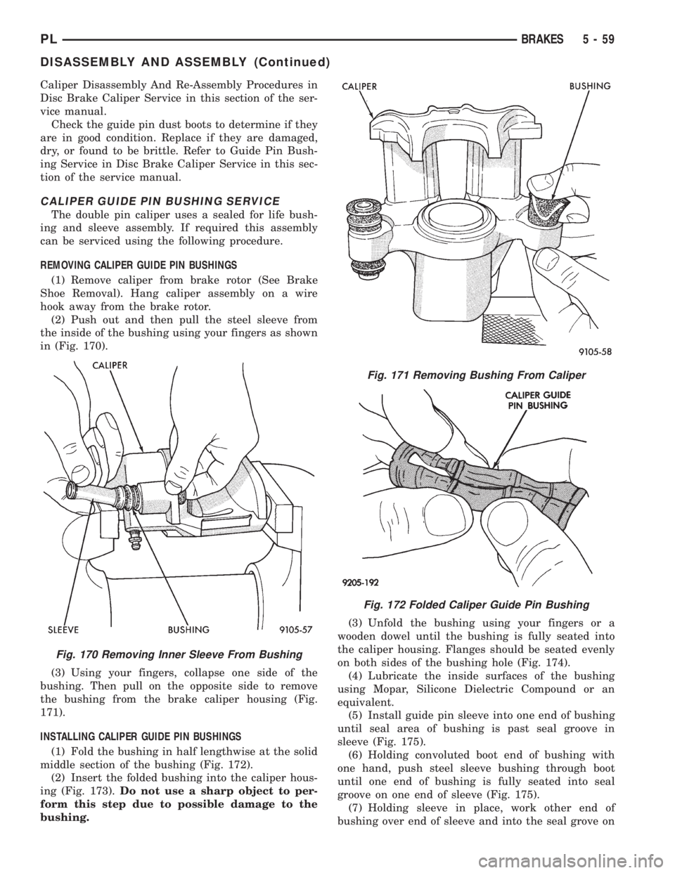
(2) Push out and then pull the steel sleeve from
the inside of the bushing using your fingers as shown
in (Fig. 170).
(3) Using your fingers, collapse one side of the
bushing. Then pull on the opposite side to remove
the bushing from the brake caliper housing (Fig.
171).
INSTALLING CALIPER GUIDE PIN BUSHINGS
(1) Fold the bushing in half lengthwise at the solid
middle section of the bushing (Fig. 172).
(2) Insert the folded bushing into the caliper hous-
ing (Fig. 173).Do not use a sharp object to per-
form this step due to possible damage to the
bushing.(3) Unfold the bushing using your fingers or a
wooden dowel until the bushing is fully seated into
the caliper housing. Flanges should be seated evenly
on both sides of the bushing hole (Fig. 174).
(4) Lubricate the inside surfaces of the bushing
using Mopar, Silicone Dielectric Compound or an
equivalent.
(5) Install guide pin sleeve into one end of bushing
until seal area of bushing is past seal groove in
sleeve (Fig. 175).
(6) Holding convoluted boot end of bushing with
one hand, push steel sleeve bushing through boot
until one end of bushing is fully seated into seal
groove on one end of sleeve (Fig. 175).
(7) Holding sleeve in place, work other end of
bushing over end of sleeve and into the seal grove on
Fig. 170 Removing Inner Sleeve From Bushing
Fig. 171 Removing Bushing From Caliper
Fig. 172 Folded Caliper Guide Pin Bushing
PLBRAKES 5 - 59
DISASSEMBLY AND ASSEMBLY (Continued)
Page 143 of 1200
(12) Inspect caliper piston for pitting, scratches, or
any physical damage. Replace piston if there is evi-
dence of scratches, pitting or physical damage.
CALIPER ASSEMBLY
CAUTION: Excessive vise pressure will cause bore
distortion and binding of piston.
(1) Clamp caliper in a vise (with protective caps
installed on jaws of vise).
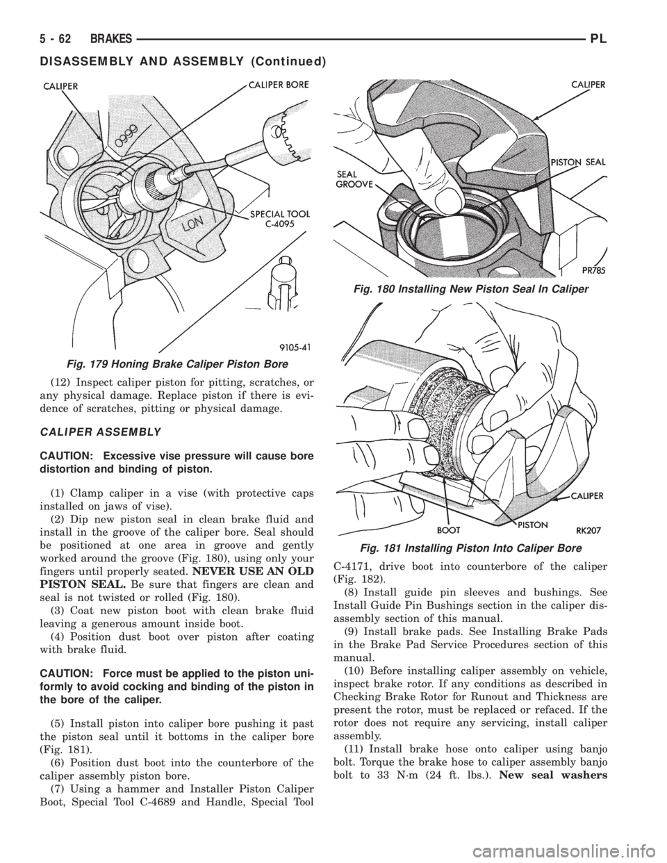
(2) Dip new piston seal in clean brake fluid and
install in the groove of the caliper bore. Seal should
be positioned at one area in groove and gently
worked around the groove (Fig. 180), using only your
fingers until properly seated.NEVER USE AN OLD
PISTON SEAL.Be sure that fingers are clean and
seal is not twisted or rolled (Fig. 180).
(3) Coat new piston boot with clean brake fluid
leaving a generous amount inside boot.
(4) Position dust boot over piston after coating
with brake fluid.
CAUTION: Force must be applied to the piston uni-
formly to avoid cocking and binding of the piston in
the bore of the caliper.
(5) Install piston into caliper bore pushing it past
the piston seal until it bottoms in the caliper bore
(Fig. 181).
(6) Position dust boot into the counterbore of the
caliper assembly piston bore.
(7) Using a hammer and Installer Piston Caliper
Boot, Special Tool C-4689 and Handle, Special ToolC-4171, drive boot into counterbore of the caliper
(Fig. 182).
(8) Install guide pin sleeves and bushings. See
Install Guide Pin Bushings section in the caliper dis-
assembly section of this manual.
(9) Install brake pads. See Installing Brake Pads
in the Brake Pad Service Procedures section of this
manual.
(10) Before installing caliper assembly on vehicle,
inspect brake rotor. If any conditions as described in
Checking Brake Rotor for Runout and Thickness are
present the rotor, must be replaced or refaced. If the
rotor does not require any servicing, install caliper
assembly.
(11) Install brake hose onto caliper using banjo
bolt. Torque the brake hose to caliper assembly banjo
bolt to 33 N´m (24 ft. lbs.).New seal washers
Fig. 179 Honing Brake Caliper Piston Bore
Fig. 180 Installing New Piston Seal In Caliper
Fig. 181 Installing Piston Into Caliper Bore
5 - 62 BRAKESPL
DISASSEMBLY AND ASSEMBLY (Continued)
Page 154 of 1200
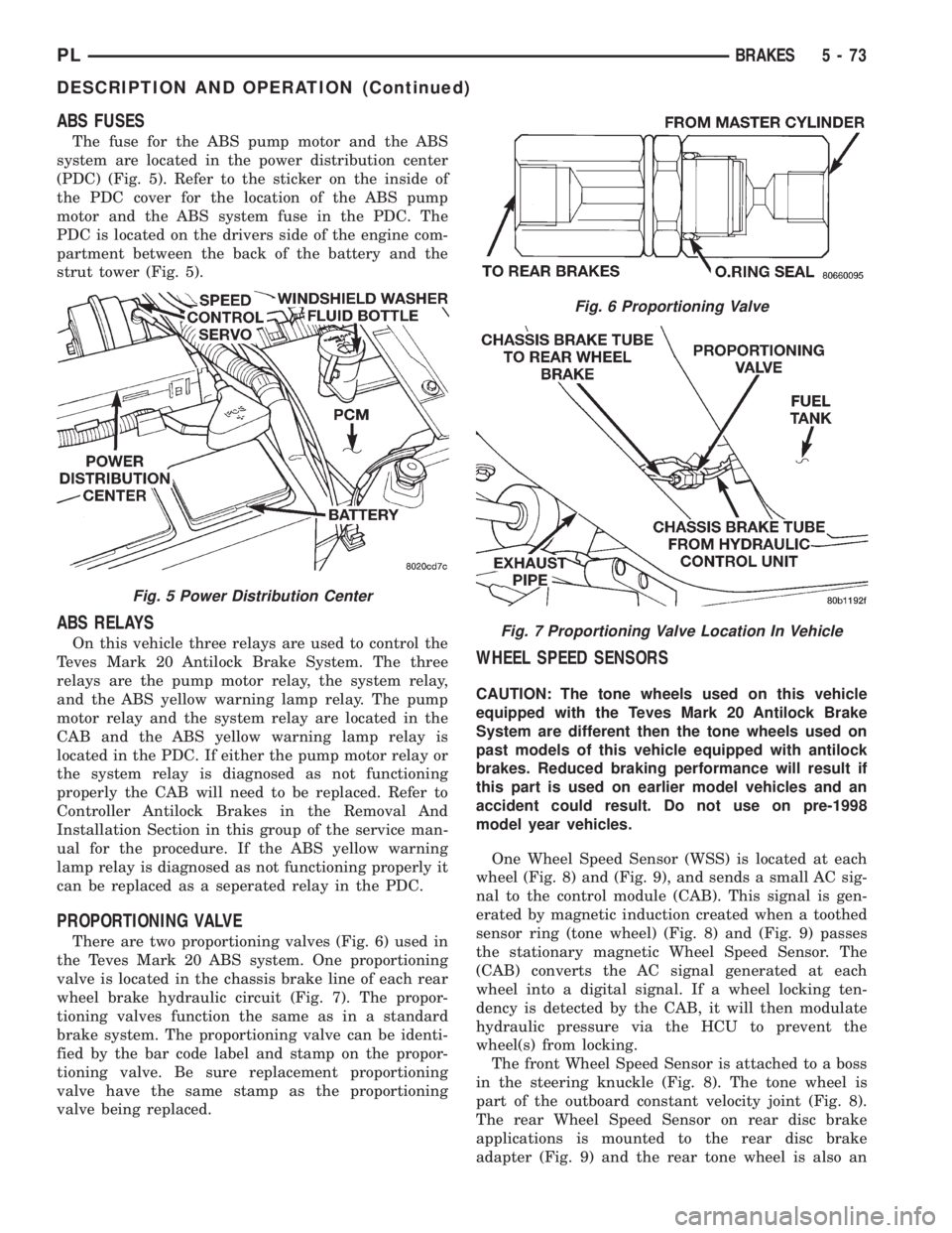
ABS FUSES
The fuse for the ABS pump motor and the ABS
system are located in the power distribution center
(PDC) (Fig. 5). Refer to the sticker on the inside of
the PDC cover for the location of the ABS pump
motor and the ABS system fuse in the PDC. The
PDC is located on the drivers side of the engine com-
partment between the back of the battery and the
strut tower (Fig. 5).
ABS RELAYS
On this vehicle three relays are used to control the
Teves Mark 20 Antilock Brake System. The three
relays are the pump motor relay, the system relay,
and the ABS yellow warning lamp relay. The pump
motor relay and the system relay are located in the
CAB and the ABS yellow warning lamp relay is
located in the PDC. If either the pump motor relay or
the system relay is diagnosed as not functioning
properly the CAB will need to be replaced. Refer to
Controller Antilock Brakes in the Removal And
Installation Section in this group of the service man-
ual for the procedure. If the ABS yellow warning
lamp relay is diagnosed as not functioning properly it
can be replaced as a seperated relay in the PDC.
PROPORTIONING VALVE
There are two proportioning valves (Fig. 6) used in
the Teves Mark 20 ABS system. One proportioning
valve is located in the chassis brake line of each rear
wheel brake hydraulic circuit (Fig. 7). The propor-
tioning valves function the same as in a standard
brake system. The proportioning valve can be identi-
fied by the bar code label and stamp on the propor-
tioning valve. Be sure replacement proportioning
valve have the same stamp as the proportioning
valve being replaced.
WHEEL SPEED SENSORS
CAUTION: The tone wheels used on this vehicle
equipped with the Teves Mark 20 Antilock Brake
System are different then the tone wheels used on
past models of this vehicle equipped with antilock
brakes. Reduced braking performance will result if
this part is used on earlier model vehicles and an
accident could result. Do not use on pre-1998
model year vehicles.
One Wheel Speed Sensor (WSS) is located at each
wheel (Fig. 8) and (Fig. 9), and sends a small AC sig-
nal to the control module (CAB). This signal is gen-
erated by magnetic induction created when a toothed
sensor ring (tone wheel) (Fig. 8) and (Fig. 9) passes
the stationary magnetic Wheel Speed Sensor. The
(CAB) converts the AC signal generated at each
wheel into a digital signal. If a wheel locking ten-
dency is detected by the CAB, it will then modulate
hydraulic pressure via the HCU to prevent the
wheel(s) from locking.
The front Wheel Speed Sensor is attached to a boss
in the steering knuckle (Fig. 8). The tone wheel is
part of the outboard constant velocity joint (Fig. 8).
The rear Wheel Speed Sensor on rear disc brake
applications is mounted to the rear disc brake
adapter (Fig. 9) and the rear tone wheel is also an
Fig. 5 Power Distribution Center
Fig. 6 Proportioning Valve
Fig. 7 Proportioning Valve Location In Vehicle
PLBRAKES 5 - 73
DESCRIPTION AND OPERATION (Continued)
Page 201 of 1200
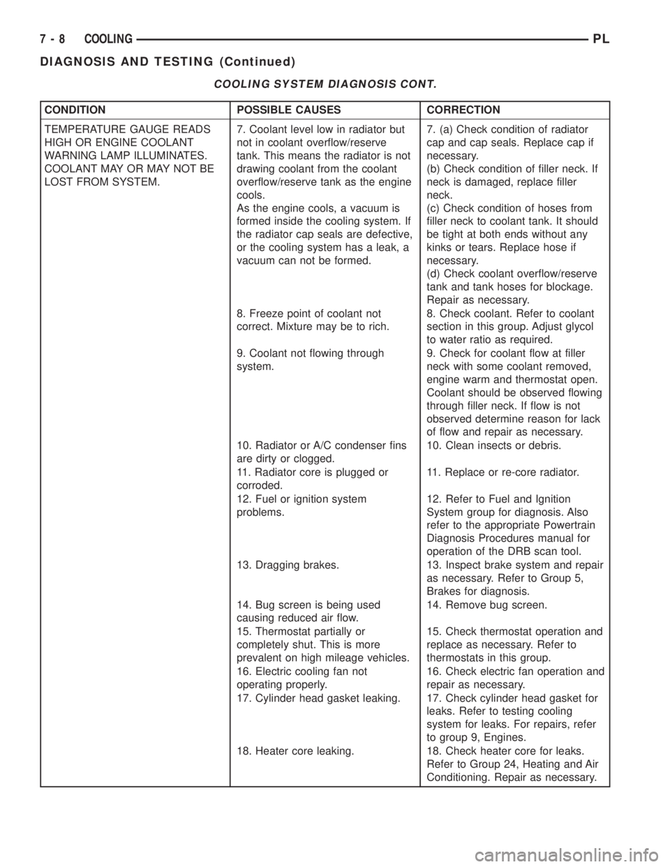
COOLING SYSTEM DIAGNOSIS CONT.
CONDITION POSSIBLE CAUSES CORRECTION
TEMPERATURE GAUGE READS
HIGH OR ENGINE COOLANT
WARNING LAMP ILLUMINATES.
COOLANT MAY OR MAY NOT BE
LOST FROM SYSTEM.7. Coolant level low in radiator but
not in coolant overflow/reserve
tank. This means the radiator is not
drawing coolant from the coolant
overflow/reserve tank as the engine
cools.
As the engine cools, a vacuum is
formed inside the cooling system. If
the radiator cap seals are defective,
or the cooling system has a leak, a
vacuum can not be formed.7. (a) Check condition of radiator
cap and cap seals. Replace cap if
necessary.
(b) Check condition of filler neck. If
neck is damaged, replace filler
neck.
(c) Check condition of hoses from
filler neck to coolant tank. It should
be tight at both ends without any
kinks or tears. Replace hose if
necessary.
(d) Check coolant overflow/reserve
tank and tank hoses for blockage.
Repair as necessary.
8. Freeze point of coolant not
correct. Mixture may be to rich.8. Check coolant. Refer to coolant
section in this group. Adjust glycol
to water ratio as required.
9. Coolant not flowing through
system.9. Check for coolant flow at filler
neck with some coolant removed,
engine warm and thermostat open.
Coolant should be observed flowing
through filler neck. If flow is not
observed determine reason for lack
of flow and repair as necessary.
10. Radiator or A/C condenser fins
are dirty or clogged.10. Clean insects or debris.
11. Radiator core is plugged or
corroded.11. Replace or re-core radiator.
12. Fuel or ignition system
problems.12. Refer to Fuel and Ignition
System group for diagnosis. Also
refer to the appropriate Powertrain
Diagnosis Procedures manual for
operation of the DRB scan tool.
13. Dragging brakes. 13. Inspect brake system and repair
as necessary. Refer to Group 5,
Brakes for diagnosis.
14. Bug screen is being used
causing reduced air flow.14. Remove bug screen.
15. Thermostat partially or
completely shut. This is more
prevalent on high mileage vehicles.15. Check thermostat operation and
replace as necessary. Refer to
thermostats in this group.
16. Electric cooling fan not
operating properly.16. Check electric fan operation and
repair as necessary.
17. Cylinder head gasket leaking. 17. Check cylinder head gasket for
leaks. Refer to testing cooling
system for leaks. For repairs, refer
to group 9, Engines.
18. Heater core leaking. 18. Check heater core for leaks.
Refer to Group 24, Heating and Air
Conditioning. Repair as necessary.
7 - 8 COOLINGPL
DIAGNOSIS AND TESTING (Continued)