fuel cap DODGE NEON 1999 Service Repair Manual
[x] Cancel search | Manufacturer: DODGE, Model Year: 1999, Model line: NEON, Model: DODGE NEON 1999Pages: 1200, PDF Size: 35.29 MB
Page 3 of 1200
ENGINE OIL
SAE VISCOSITY RATING INDICATES ENGINE OIL VISCOSITY
An SAE viscosity grade is used to specify the vis-
cosity of engine oil. SAE 30 specifies a single viscos-
ity engine oil. Engine oils also have multiple
viscosities. These are specified with a dual SAE vis-
cosity grade which indicates the cold-to-hot tempera-
ture viscosity range.
²SAE 30 = single grade engine oil.
²SAE 10W-30 = multiple grade engine oil.
API QUALITY CLASSIFICATION
The API Service Grade specifies the type of perfor-
mance the engine oil is intended to provide. The API
Service Grade specifications also apply to energy con-
serving engine oils.
Use engine oils that are API Service Certified.
5W-30 and 10W-30 MOPAR engine oils conform to
specifications.
Refer to Group 9, Engine for engine oil specifica-
tion.
GEAR LUBRICANTS
SAE ratings also apply to multiple grade gear
lubricants. In addition, API classification defines the
lubricants usage.
LUBRICANTS AND GREASES
Lubricating grease is rated for quality and usage
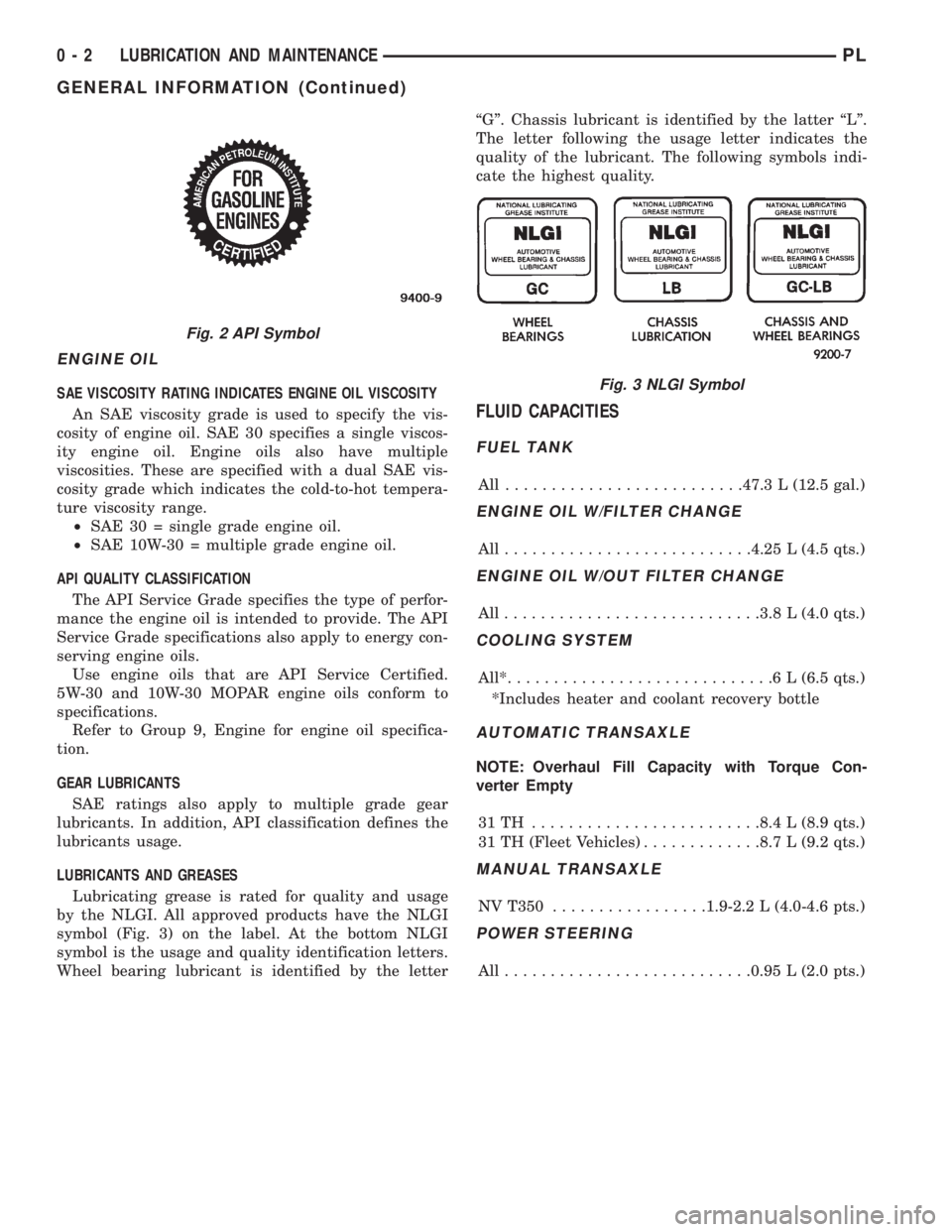
by the NLGI. All approved products have the NLGI
symbol (Fig. 3) on the label. At the bottom NLGI
symbol is the usage and quality identification letters.
Wheel bearing lubricant is identified by the letterªGº. Chassis lubricant is identified by the latter ªLº.
The letter following the usage letter indicates the
quality of the lubricant. The following symbols indi-
cate the highest quality.
FLUID CAPACITIES
FUEL TANK
All ..........................47.3 L (12.5 gal.)
ENGINE OIL W/FILTER CHANGE
All...........................4.25 L (4.5 qts.)
ENGINE OIL W/OUT FILTER CHANGE
All............................3.8 L (4.0 qts.)
COOLING SYSTEM
All*.............................6L(6.5 qts.)
*Includes heater and coolant recovery bottle
AUTOMATIC TRANSAXLE
NOTE: Overhaul Fill Capacity with Torque Con-
verter Empty
31TH .........................8.4 L (8.9 qts.)
31 TH (Fleet Vehicles).............8.7 L (9.2 qts.)
MANUAL TRANSAXLE
NV T350.................1.9-2.2 L (4.0-4.6 pts.)
POWER STEERING
All...........................0.95 L (2.0 pts.)
Fig. 2 API Symbol
Fig. 3 NLGI Symbol
0 - 2 LUBRICATION AND MAINTENANCEPL
GENERAL INFORMATION (Continued)
Page 201 of 1200
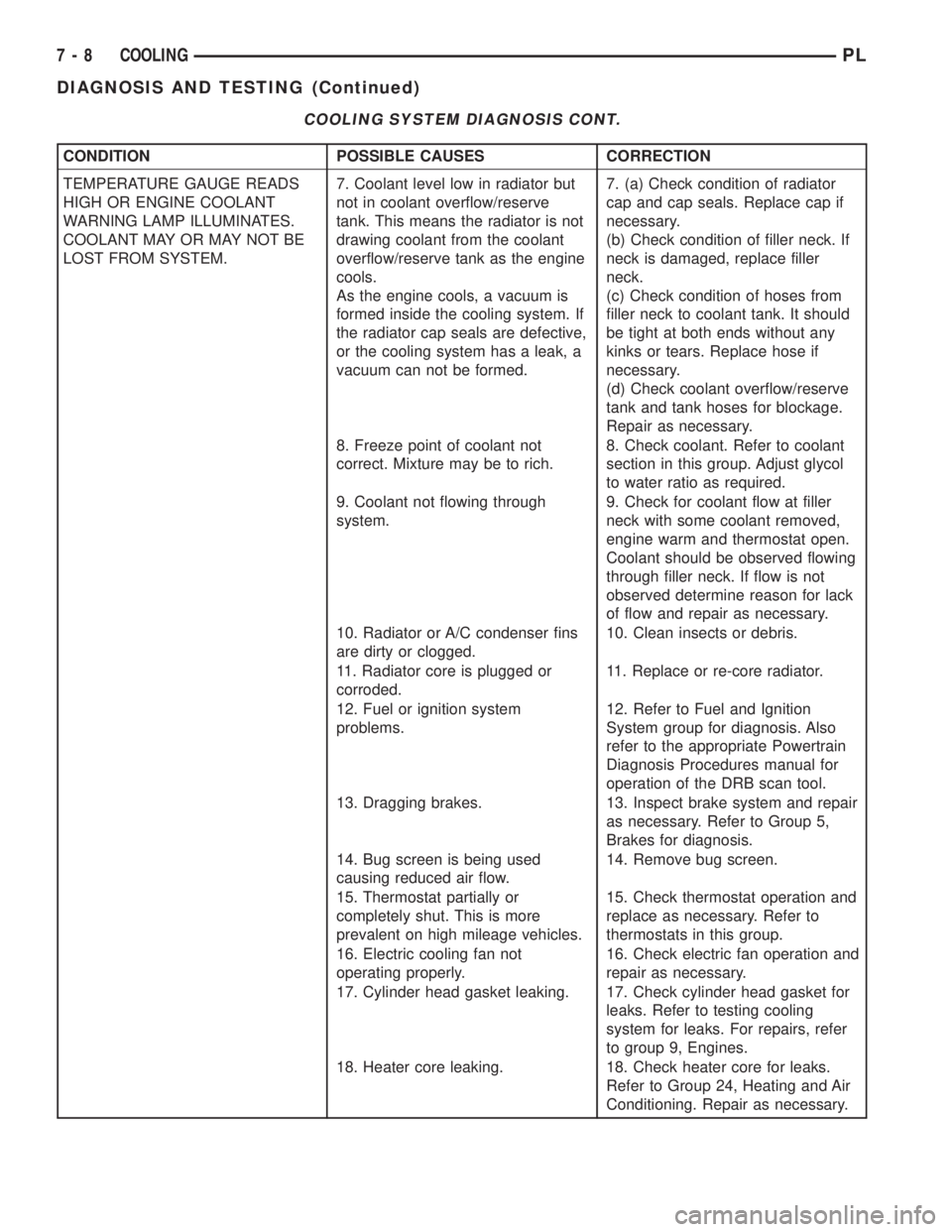
COOLING SYSTEM DIAGNOSIS CONT.
CONDITION POSSIBLE CAUSES CORRECTION
TEMPERATURE GAUGE READS
HIGH OR ENGINE COOLANT
WARNING LAMP ILLUMINATES.
COOLANT MAY OR MAY NOT BE
LOST FROM SYSTEM.7. Coolant level low in radiator but
not in coolant overflow/reserve
tank. This means the radiator is not
drawing coolant from the coolant
overflow/reserve tank as the engine
cools.
As the engine cools, a vacuum is
formed inside the cooling system. If
the radiator cap seals are defective,
or the cooling system has a leak, a
vacuum can not be formed.7. (a) Check condition of radiator
cap and cap seals. Replace cap if
necessary.
(b) Check condition of filler neck. If
neck is damaged, replace filler
neck.
(c) Check condition of hoses from
filler neck to coolant tank. It should
be tight at both ends without any
kinks or tears. Replace hose if
necessary.
(d) Check coolant overflow/reserve
tank and tank hoses for blockage.
Repair as necessary.
8. Freeze point of coolant not
correct. Mixture may be to rich.8. Check coolant. Refer to coolant
section in this group. Adjust glycol
to water ratio as required.
9. Coolant not flowing through
system.9. Check for coolant flow at filler
neck with some coolant removed,
engine warm and thermostat open.
Coolant should be observed flowing
through filler neck. If flow is not
observed determine reason for lack
of flow and repair as necessary.
10. Radiator or A/C condenser fins
are dirty or clogged.10. Clean insects or debris.
11. Radiator core is plugged or
corroded.11. Replace or re-core radiator.
12. Fuel or ignition system
problems.12. Refer to Fuel and Ignition
System group for diagnosis. Also
refer to the appropriate Powertrain
Diagnosis Procedures manual for
operation of the DRB scan tool.
13. Dragging brakes. 13. Inspect brake system and repair
as necessary. Refer to Group 5,
Brakes for diagnosis.
14. Bug screen is being used
causing reduced air flow.14. Remove bug screen.
15. Thermostat partially or
completely shut. This is more
prevalent on high mileage vehicles.15. Check thermostat operation and
replace as necessary. Refer to
thermostats in this group.
16. Electric cooling fan not
operating properly.16. Check electric fan operation and
repair as necessary.
17. Cylinder head gasket leaking. 17. Check cylinder head gasket for
leaks. Refer to testing cooling
system for leaks. For repairs, refer
to group 9, Engines.
18. Heater core leaking. 18. Check heater core for leaks.
Refer to Group 24, Heating and Air
Conditioning. Repair as necessary.
7 - 8 COOLINGPL
DIAGNOSIS AND TESTING (Continued)
Page 207 of 1200
WATER PUMP DIAGNOSIS
A quick flow test to tell whether or not the pump is
working is to see if the heater warms properly. A
defective pump will not be able to circulate heated
coolant through the long heater hose.
Another flow test to help determine pump opera-
tion.
WARNING: DO NOT remove radiator cap if the cool-
ing system is hot or under pressure.
(1) Remove radiator cap.
(2) Remove a small amount of coolant from the
system, start the engine and warm up until thermo-
stat opens. With the thermostat open and coolant
level low you will see if the water pump is pumping
coolant through the system.
COOLING SYSTEM FLOW CHECK
To determine whether coolant is flowing through
the cooling system, use the following procedures:
(1) If engine is cold, idle engine until normal oper-
ating temperature is reached. Then feel the upper
radiator hose. If it is hot, coolant is circulating.
WARNING: DO NOT REMOVE THE COOLING SYS-
TEM PRESSURE CAP WITH THE SYSTEM HOT AND
UNDER PRESSURE BECAUSE SERIOUS BURNS
FROM COOLANT CAN OCCUR.
(2) Remove pressure cap when engine is cold,
remove small amount of coolant Idle engine until
thermostat opens, you should observe coolant flow
while looking down the filler neck. Once flow is
detected install the pressure cap.
RADIATOR FAN CONTROL
Fan control is accomplished two ways. The fan
always runs when the air conditioning compressor
clutch is engaged. In addition to this control, the fan
is turned on by the temperature of the coolant which
is sensed by the coolant temperature sensor which
sends the message to the Powertrain Control Module
(PCM). The (PCM) turns on the fan through the
Solid State Fan Relay. The Solid State Fan Relay is
located on the left front inner frame just behind the
radiator. See Wiring Diagrams Manual for circuity
and diagnostics provided.
Switching through the (PCM) provides fan control
for the following conditions.
²The fan will not run during cranking until the
engine starts no matter what the coolant tempera-
ture is.
²Fan will run when the air conditioning clutch is
engaged and low pressure cutout switch is closed.
²Fan will run at vehicle speeds above about 40
mph only if coolant temperature reaches 110ÉC(230ÉF). It will turn off when the temperature drops
to 104ÉC (220ÉF). At speeds below 40 mph the fan
switches on at 102ÉC (215ÉF) and off at 93ÉC (200ÉF).
Refer to Radiator Fan Control Module Group 14,
Fuel Injection for more information.
ELECTRIC FAN MOTOR TEST
Refer to Powertrain Diagnostic Manual for procedure.
TESTING COOLING SYSTEM FOR LEAKS
The system should be full. With the engine not
running, wipe the filler neck sealing seat clean.
Attach a radiator pressure tester to the filler neck,
as shown in (Fig. 9) and apply 104 kPa (15 psi) pres-
sure. If the pressure drops more than 2 psi in 2 min-
utes, inspect the system for external leaks.
Move all hoses at the radiator and heater while
system is pressurize at 15 psi, since some leaks occur
due to engine rock while driving.
If there are no external leaks after the gauge dial
shows a drop in pressure, detach the tester. Start the
engine, and run the engine to normal operating tem-
perature in order to open the thermostat and allow
the coolant to expand. Reattach the tester. If the nee-
dle on the dial fluctuates it indicates a combustion
leak, usually a head gasket leak.
WARNING: WITH THE PRESSURE TESTER IN
PLACE PRESSURE BUILDS UP QUICKLY. ANY
EXCESSIVE PRESSURE BUILD-UP DUE TO CON-
TINUOUS ENGINE OPERATION MUST BE
RELEASED TO A SAFE PRESSURE POINT. NEVER
PERMIT PRESSURE TO EXCEED 138 kPa (20 psi).
If the needle on the dial does not fluctuate, race
the engine a few times. If an abnormal amount of
coolant or steam is emitted from the tail pipe, it may
indicate a faulty head gasket, cracked engine block,
or cracked cylinder head.
Fig. 9 Pressure Testing Cooling SystemÐTypical
7 - 14 COOLINGPL
DIAGNOSIS AND TESTING (Continued)
Page 231 of 1200
charge battery if necessary. Disconnect all testing
equipment and connect ASD relay or the Fuel Sole-
noid. Start the vehicle several times to assure the
problem has been corrected.
STARTING SYSTEM TEST
For circuit descriptions and diagrams, refer to
8W-21, Starting System in Group 8W, Wiring Dia-
grams.
WARNING: ON VEHICLES EQUIPPED WITH AIR-
BAGS, REFER TO GROUP 8M - PASSIVE
RESTRAINT SYSTEMS BEFORE ATTEMPTING
STEERING WHEEL, STEERING COLUMN, OR
INSTRUMENT PANEL COMPONENT DIAGNOSIS OR
SERVICE. FAILURE TO TAKE THE PROPER PRE-
CAUTIONS COULD RESULT IN ACCIDENTAL AIR-
BAG DEPLOYMENT AND POSSIBLE PERSONAL
INJURY.
INSPECTION
Before removing any unit from the starting system
for repair or diagnosis, perform the following inspec-
tions:
²Battery- Visually inspect the battery for indi-
cations of physical damage and loose or corroded
cable connections. Determine the state-of-charge and
cranking capacity of the battery. Charge or replace
the battery, if required. Refer to Group 8A, Battery
for more information.²Ignition Switch- Visually inspect the ignition
switch for indications of physical damage and loose
or corroded wire harness connections.
²Clutch Pedal Position Switch- Visually
inspect the clutch pedal position switch for indica-
tions of physical damage and loose or corroded wire
harness connections.
²Park/Neutral Position Switch- Visually
inspect the park/neutral position switch for indica-
tions of physical damage and loose or corroded wire
harness connections.
²Starter Relay- Visually inspect the starter
relay for indications of physical damage and loose or
corroded wire harness connections.
²Starter- Visually inspect the starter for indica-
tions of physical damage and loose or corroded wire
harness connections.
²Starter Solenoid- Visually inspect the starter
solenoid for indications of physical damage and loose
or corroded wire harness connections.
²Wiring- Visually inspect the wire harness for
damage. Repair or replace any faulty wiring, as
required.
8B - 4 STARTINGPL
DIAGNOSIS AND TESTING (Continued)
Page 412 of 1200
8W-10 POWER DISTRIBUTION
Component Page
A/C Compressor Clutch.............8W-10-14, 15
A/C Compressor Clutch Relay........8W-10-14, 15
Automatic Shut Down Relay............8W-10-16
Battery...........................8W-10-5, 6
Capacitor..........................8W-10-16
Circuit Breaker.......................8W-10-8
Clutch Pedal Position Switch.......8W-10-9, 10, 11
Controller Anti-Lock Brake.......8W-10-12, 14, 15
Data Link Connector..................8W-10-16
Diode No. 1......................8W-10-14, 15
Diode No. 2.........................8W-10-13
Dome Lamp........................8W-10-13
Downstream Heated Oxygen Sensor......8W-10-16
Engine Starter Motor..................8W-10-7
Engine Starter Motor Relay......8W-10-7, 9, 10, 11
Fog Lamp Relay.....................8W-10-17
Fuel Injector No. 1...................8W-10-16
Fuel Injector No. 2...................8W-10-16
Fuel Injector No. 3...................8W-10-16
Fuel Injector No. 4...................8W-10-16
Fuel Pump Module...................8W-10-16
Fuel Pump Relay....................8W-10-16
Fuse 1 (FB)..........................8W-10-8
Fuse 2 (FB)..........................8W-10-8
Fuse 2 (PDC).....................8W-10-5, 6, 7
Fuse 3 (FB)..........................8W-10-8
Fuse 3 (PDC).....................8W-10-5, 6, 8
Fuse 4 (FB)..........................8W-10-8
Fuse 5 (FB)..........................8W-10-8
Fuse 5 (PDC)....................8W-10-5, 6, 12
Fuse 6 (FB)..........................8W-10-8
Fuse 7 (FB)..........................8W-10-8
Fuse 8 (FB)..........................8W-10-8
Fuse 8 (PDC)....................8W-10-5, 6, 12
Fuse 9 (FB).......................8W-10-9, 10
Fuse 10 (FB)...................8W-10-9, 10, 11
Fuse 10 (PDC)...................8W-10-5, 6, 12
Fuse 11 (FB)...................8W-10-9, 10, 11
Fuse 11 (PDC)....................8W-10-5, 6, 7
Fuse 12 (FB)........................8W-10-11
Fuse 13 (PDC)...................8W-10-5, 6, 13
Fuse 14 (FB)...................8W-10-9, 10, 11
Fuse 15 (FB)...................8W-10-9, 10, 11
Fuse 16 (FB)...................8W-10-9, 10, 11Component Page
Fuse 16 (PDC).....................8W-10-6, 17
Fuse 18 (PDC)................8W-10-5, 6, 14, 15
Fuse 20 (PDC)................8W-10-5, 6, 14, 15
Fuse 21 (PDC)...................8W-10-5, 6, 16
Fuse 23 (PDC)................8W-10-5, 6, 14, 15
Fuse 25 (PDC)................8W-10-5, 6, 14, 15
Fuse Block...................8W-10-8, 9, 10, 11
G101...............................8W-10-9
G204...............................8W-10-7
Generator..........................8W-10-16
Glove Box Lamp And Switch............8W-10-13
Headlamp Switch.....................8W-10-8
High Speed Warning Module...........8W-10-13
Horn..............................8W-10-14
Horn No. 1.........................8W-10-15
Horn No. 2.........................8W-10-15
Horn Relay......................8W-10-14, 15
Ignition Coil Pack....................8W-10-16
Ignition Switch.............8W-10-7, 8, 9, 10, 11
Immobilizer......................8W-10-10, 11
Instrument Cluster.................8W-10-7, 13
Left Fog Lamp......................8W-10-17
Left Visor/Vanity Lamps...............8W-10-13
Map/Reading Lamps..................8W-10-13
Noise Supressor.....................8W-10-16
Power Distribution
Center.....8W-10-5, 6, 7, 8, 12, 13, 14, 15, 16, 17
Power Mirror Switch..................8W-10-13
Powertrain Control Module...........8W-10-9, 16
Radiator Fan Motor..................8W-10-12
Radio..............................8W-10-13
Rear Fog Lamp Switch................8W-10-17
Rear Window Defogger Switch..........8W-10-12
Right Fog Lamp.....................8W-10-17
Right Visor/Vanity Lamps..............8W-10-13
Solid State Fan Relay.................8W-10-12
Stop Lamp Switch.................8W-10-14, 15
Time Delay Relay....................8W-10-13
Time Out Relay......................8W-10-13
Trunk Lamp........................8W-10-13
Turn Signal/Hazard Switch..........8W-10-14, 15
Underhood Lamp....................8W-10-13
Upstream Heated Oxygen Sensor........8W-10-16
PL8W - 10 POWER DISTRIBUTION 8W - 10 - 1
Page 427 of 1200

21FUSE20A
21
52
55
60
57
BATT A0
POWER
DISTRIBUTION
CENTER
72
A14
16
RD/WT
A14
16
RD/WT
POWERTRAIN
CONTROL
MODULE
A14
18
RD/WT
5C105
A141
16
DG/WT
A141
18
DG/WT
4
FUEL
PUMP
MODULE
A142
18
DG/OR
S105
22
FUEL
PUMP
RELAYAUTOMATIC
SHUT
DOWN
RELAY
6C161
DG/OR18 A142
GENERATOR
A142
18
DG/ORA142
18
DG/OR
POWERTRAIN
CONTROL
MODULE
SENSOR OXYGEN
HEATED
UPSTREAM
A142
18
DG/ORA142
18
DG/OR
A142
18
DG/OR
A142
18
DG/OR A142
18
DG/ORDG/OR18 A142
DG/OR18 A142 A142
18
DG/OR
IGNITION
COIL
PACKSUPRESSOR
NOISE
S139S121
S122
2
DG/OR18 A142
DG/OR18 A142
2222
2161C2
58
FUEL
INJECTOR
NO. 1 NO. 2INJECTOR
FUEL FUEL
INJECTOR
NO. 3FUEL
INJECTOR
NO. 4
CONNECTORLINK DATA
46C116
(2.0L)
SENSOR
OXYGEN
HEATED
DOWNSTREAM
BUILT-UP-EXPORT) (EXCEPT
CAPACITOR
(8W-30-2) (8W-30-11)(8W-10-5)
(8W-30-11)
(8W-30-2)(8W-10-5)
(8W-10-6)
(8W-20-2)
(8W-30-2)
(8W-30-3)
(8W-30-5) (8W-30-5) (8W-30-5) (8W-30-5) (8W-30-5)(8W-30-4)
(8W-30-3)
8W - 10 - 16 8W-10 POWER DISTRIBUTIONPL
J988W-18205
Page 721 of 1200
cause of low compression unless some malfunc-
tion is present.
(11) Clean or replace spark plugs as necessary
and adjust gap as specified in Group 8, Electrical.
Tighten to specifications.
(12) Test resistance of spark plug cables. Refer to
Group 8, Electrical Ignition System Secondary Cir-
cuit Inspection.
(13) Test coil output voltage, primary and second-
ary resistance. Replace parts as necessary. Refer to
Group 8, Electrical Ignition System.
(14) Check fuel pump pressure at idle and differ-
ent RPM ranges. Refer to Group 14, Fuel System for
Specifications.
(15) The air filter elements should be replaced as
specified in Group 0, Lubrication and Maintenance,.
(16) Inspect crankcase ventilation system as out
lined in Group 0, Lubrication and Maintenance. For
emission controls see Group 25, Emission Controls
for service procedures.
(17) Inspect and adjust accessory belt drives refer-
ring to Group 7, Cooling System, Accessory Drive
Belts for proper adjustments.
(18) Road test vehicle as a final test.
CYLINDER COMBUSTION PRESSURE LEAKAGE
TEST
The combustion pressure leakage test provides an
accurate means for determining engine condition.
Combustion pressure leakage testing will detect:
²Exhaust and intake valve leaks (improper seat-
ing).
²Leaks between adjacent cylinders or into water
jacket.
²Any causes for combustion/compression pressure
loss.
WARNING: DO NOT REMOVE THE RADIATOR CAP
WITH THE SYSTEM HOT AND UNDER PRESSURE
BECAUSE SERIOUS BURNS FROM COOLANT CAN
OCCUR.
Check the coolant level and fill as required. DO
NOT install the radiator cap.
Start and operate the engine until it attains nor-
mal operating temperature, then turn the engine
OFF.
Clean spark plug recesses with compressed air.
Remove the spark plugs.
Remove the oil filler cap.
Remove the air cleaner.
Calibrate the tester according to the manufactur-
er's instructions. The shop air source for testing
should maintain 483 kPa (70 psi) minimum, 1 379
kPa (200 psi) maximum and 552 kPa (80 psi) recom-
mended.Perform the test procedures on each cylinder
according to the tester manufacturer's instructions.
While testing, listen for pressurized air escaping
through the throttle body, tailpipe and oil filler cap
opening. Check for bubbles in the radiator coolant.
All gauge pressure indications should be equal,
with no more than 25% leakage.
FOR EXAMPLE:At 552 kPa (80 psi) input pres-
sure, a minimum of 414 kPa (60 psi) should be main-
tained in the cylinder.
LASH ADJUSTER (TAPPET) NOISE DIAGNOSIS
A tappet-like noise may be produced from several
items. Check the following items.
(1) Engine oil level too high or too low. This may
cause aerated oil to enter the adjusters and cause
them to be spongy.
(2) Insufficient running time after rebuilding cylin-
der head. Low speed running up to 1 hour may be
required.
(3) During this time, turn engine off and let set for
a few minutes before restarting. Repeat this several
times after engine has reached normal operating
temperature.
(4) Low oil pressure.
(5) The oil restrictor pressed into the vertical oil
passage to the cylinder head is plugged with debris.
(6) Air ingested into oil due to broken or cracked
oil pump pick up.
(7) Worn valve guides.
(8) Rocker arm ears contacting valve spring
retainer.
(9) Rocker arm loose, adjuster stuck or at maxi-
mum extension and still leaves lash in the system.
(10) Faulty lash adjuster.
a. Check lash adjusters for sponginess while
installed in cylinder head. Depress part of rocker
arm over adjuster. Normal adjusters should feel very
firm. Spongy adjusters can be bottomed out easily.
b. Remove suspected rocker arms (sohc) or lash
adjuster (dohc) and replace.
INSPECTION (ENGINE OIL LEAKS IN GENERAL)
Begin with a through visual inspection of the
engine, particularly at the area of the suspected leak.
If an oil leak source is not readily identifiable, the
following steps should be followed:
(1) Do not clean or degrease the engine at this
time because some solvents may cause rubber to
swell, temporarily stopping the leak.
(2) Add an oil soluble dye (use as recommended by
manufacturer). Start the engine and let idle for
approximately 15 minutes. Check the oil dipstick to
make sure the dye is thoroughly mixed as indicated
with a bright yellow color under a black light.
9 - 8 ENGINEPL
DIAGNOSIS AND TESTING (Continued)
Page 821 of 1200
NOTE: When replacement is required on any com-
ponent of the exhaust system, you must use origi-
nal equipment parts (or their equivalent).
INSTALLATION
When assembling exhaust systemdo nottighten
clamps until components are aligned and clearances
are checked.
(1) Assemble catalytic convertor to exhaust mani-
fold connection. Use a new flange gasket (LEV only)
(Fig. 9) or (Fig. 10).
(2) Assemble exhaust pipe to catalytic convertor
and the support to the underbody
(3) Install the muffler to exhaust pipe and the sup-
ports to the underbody.
(4) Working from the front of system;
(5) Align and tighten the catalytic convertor to
exhaust manifold ball joint bolts to 27 N´m (20 ft.
lbs.) (Fig. 9) or flex-joint attaching nuts (LEV) to 28
N´m (250 in. lbs.).
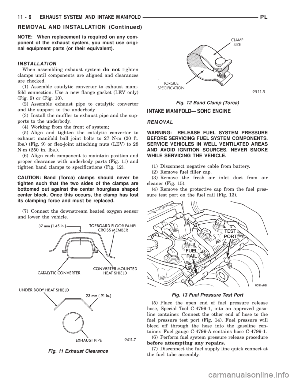
(6) Align each component to maintain position and
proper clearance with underbody parts (Fig. 11) and
tighten band clamps to specifications (Fig. 12).
CAUTION: Band (Torca) clamps should never be
tighten such that the two sides of the clamps are
bottomed out against the center hourglass shaped
center block. Once this occurs, the clamp has lost
its clamping force and must be replaced.
(7) Connect the downstream heated oxygen sensor
and lower the vehicle.
INTAKE MANIFOLDÐSOHC ENGINE
REMOVAL
WARNING: RELEASE FUEL SYSTEM PRESSURE
BEFORE SERVICING FUEL SYSTEM COMPONENTS.
SERVICE VEHICLES IN WELL VENTILATED AREAS
AND AVOID IGNITION SOURCES. NEVER SMOKE
WHILE SERVICING THE VEHICLE.
(1) Disconnect negative cable from battery.
(2) Remove fuel filler cap.
(3) Remove the fresh air inlet duct from air
cleaner (Fig. 15).
(4) Remove the protective cap from the fuel pres-
sure test port on the fuel rail (Fig. 13).
(5) Place the open end of fuel pressure release
hose, Special Tool C-4799-1, into an approved gaso-
line container. Connect the other end of hose to the
fuel pressure test port (Fig. 14). Fuel pressure will
bleed off through the hose into the gasoline con-
tainer. Fuel gauge C-4799-A contains hose C-4799-1.
(6) Perform fuel system pressure release procedure
before attempting any repairs.
(7) Disconnect the fuel supply line quick connect at
the fuel tube assembly.
Fig. 11 Exhaust Clearance
Fig. 12 Band Clamp (Torca)
Fig. 13 Fuel Pressure Test Port
11 - 6 EXHAUST SYSTEM AND INTAKE MANIFOLDPL
REMOVAL AND INSTALLATION (Continued)
Page 824 of 1200
INTAKE MANIFOLDÐDOHC ENGINE
REMOVAL
WARNING: RELEASE FUEL SYSTEM PRESSURE
BEFORE SERVICING FUEL SYSTEM COMPONENTS.
SERVICE VEHICLES IN WELL VENTILATED AREAS
AND AVOID IGNITION SOURCES. NEVER SMOKE
WHILE SERVICING THE VEHICLE.
(1) Disconnect negative cable from battery.
(2) Remove fuel filler cap.
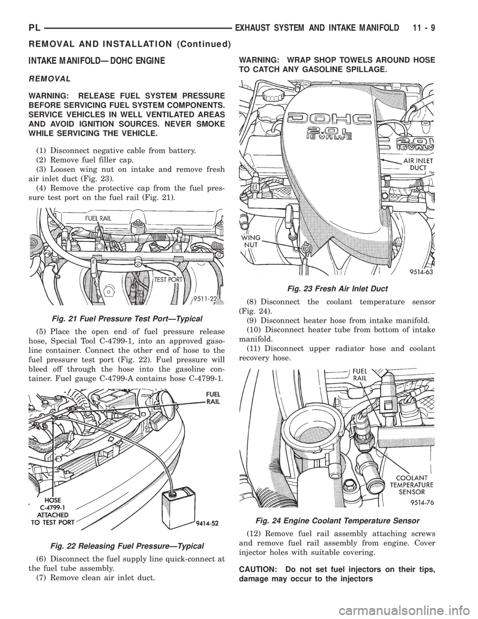
(3) Loosen wing nut on intake and remove fresh
air inlet duct (Fig. 23).
(4) Remove the protective cap from the fuel pres-
sure test port on the fuel rail (Fig. 21).
(5) Place the open end of fuel pressure release
hose, Special Tool C-4799-1, into an approved gaso-
line container. Connect the other end of hose to the
fuel pressure test port (Fig. 22). Fuel pressure will
bleed off through the hose into the gasoline con-
tainer. Fuel gauge C-4799-A contains hose C-4799-1.
(6) Disconnect the fuel supply line quick-connect at
the fuel tube assembly.
(7) Remove clean air inlet duct.WARNING: WRAP SHOP TOWELS AROUND HOSE
TO CATCH ANY GASOLINE SPILLAGE.
(8) Disconnect the coolant temperature sensor
(Fig. 24).
(9) Disconnect heater hose from intake manifold.
(10) Disconnect heater tube from bottom of intake
manifold.
(11) Disconnect upper radiator hose and coolant
recovery hose.
(12) Remove fuel rail assembly attaching screws
and remove fuel rail assembly from engine. Cover
injector holes with suitable covering.
CAUTION: Do not set fuel injectors on their tips,
damage may occur to the injectors
Fig. 21 Fuel Pressure Test PortÐTypical
Fig. 22 Releasing Fuel PressureÐTypical
Fig. 23 Fresh Air Inlet Duct
Fig. 24 Engine Coolant Temperature Sensor
PLEXHAUST SYSTEM AND INTAKE MANIFOLD 11 - 9
REMOVAL AND INSTALLATION (Continued)
Page 844 of 1200
FUEL DELIVERY SYSTEM
INDEX
page page
DESCRIPTION AND OPERATION
ELECTRIC FUEL PUMP.................... 4
FUEL DELIVERY SYSTEM.................. 3
FUEL FILTER/FUEL PRESSURE REGULATOR . . . 4
FUEL GAUGE SENDING UNIT............... 4
FUEL INJECTORS........................ 5
FUEL PUMP MODULE..................... 3
FUEL RAIL.............................. 4
FUEL TANK............................. 4
PRESSURE-VACUUM FILLER CAP........... 5
QUICK-CONNECT FITTINGS................ 5
ROLLOVER VALVES...................... 5
DIAGNOSIS AND TESTING
FUEL INJECTORS........................ 8
FUEL LEVEL SENSOR..................... 6
FUEL PUMP PRESSURE TEST.............. 6
SERVICE PROCEDURES
DRAINING FUEL TANK.................... 10
FUEL SYSTEM PRESSURE RELEASE
PROCEDURE......................... 10HOSES AND CLAMPS.................... 10
QUICK-CONNECT FITTINGS............... 11
REMOVAL AND INSTALLATION
ACCELERATOR PEDAL................... 17
AUTOMATIC SHUTDOWN RELAY........... 11
FUEL FILLER NECK...................... 16
FUEL FILLER TUBE ROLLOVER VALVE....... 16
FUEL FILTER / PRESSURE REGULATOR..... 12
FUEL INJECTORS....................... 14
FUEL LEVEL SENSOR.................... 13
FUEL PUMP INLET STRAINER............. 13
FUEL PUMP MODULE.................... 11
FUEL PUMP RELAY...................... 11
FUEL TANK............................ 15
THROTTLE CABLEÐAUTOMATIC
TRANSMISSION....................... 18
THROTTLE CABLEÐMANUAL TRANSMISSION . 17
SPECIFICATIONS
FUEL TANK CAPACITY................... 19
TORQUE.............................. 19
DESCRIPTION AND OPERATION
FUEL DELIVERY SYSTEM
The fuel delivery system consists of: the electric
fuel pump, fuel filter/fuel pressure regulator, fuel
tubes/lines/hoses, fuel rail, fuel injectors, fuel tank,
accelerator pedal and throttle cable.
A fuel return system is used on all models (all
engines). Fuel is returned through the fuel pump
module and back into the fuel tank through the fuel
filter/fuel pressure regulator. A separate fuel return
line from the engine to the tank is no longer used
with any engine.
The fuel tank assembly consists of: the fuel tank,
filler tube, fuel gauge sending unit/electric fuel pump
module, a pressure relief/rollover valve and a pres-
sure-vacuum filler cap.
Also to be considered part of the fuel system is the
evaporation control system. This is designed to
reduce the emission of fuel vapors into the atmo-
sphere. The description and function of the Evapora-
tive Control System is found in Group 25, Emission
Control Systems.
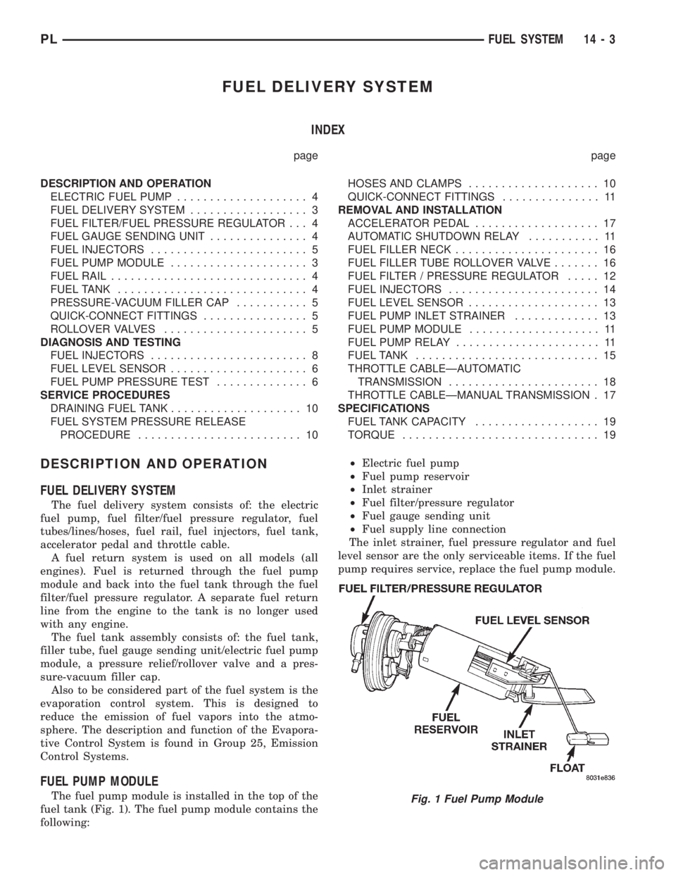
FUEL PUMP MODULE
The fuel pump module is installed in the top of the
fuel tank (Fig. 1). The fuel pump module contains the
following:²Electric fuel pump
²Fuel pump reservoir
²Inlet strainer
²Fuel filter/pressure regulator
²Fuel gauge sending unit
²Fuel supply line connection
The inlet strainer, fuel pressure regulator and fuel
level sensor are the only serviceable items. If the fuel
pump requires service, replace the fuel pump module.Fig. 1 Fuel Pump Module
PLFUEL SYSTEM 14 - 3