headlamp DODGE NEON 1999 Service Repair Manual
[x] Cancel search | Manufacturer: DODGE, Model Year: 1999, Model line: NEON, Model: DODGE NEON 1999Pages: 1200, PDF Size: 35.29 MB
Page 242 of 1200
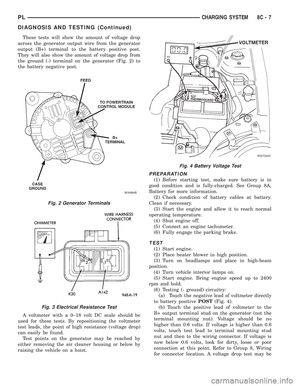
These tests will show the amount of voltage drop
across the generator output wire from the generator
output (B+) terminal to the battery positive post.
They will also show the amount of voltage drop from
the ground (-) terminal on the generator (Fig. 2) to
the battery negative post.
A voltmeter with a 0±18 volt DC scale should be
used for these tests. By repositioning the voltmeter
test leads, the point of high resistance (voltage drop)
can easily be found.
Test points on the generator may be reached by
either removing the air cleaner housing or below by
raising the vehicle on a hoist.
PREPARATION
(1) Before starting test, make sure battery is in
good condition and is fully-charged. See Group 8A,
Battery for more information.
(2) Check condition of battery cables at battery.
Clean if necessary.
(3) Start the engine and allow it to reach normal
operating temperature.
(4) Shut engine off.
(5) Connect an engine tachometer.
(6) Fully engage the parking brake.
TEST
(1) Start engine.
(2) Place heater blower in high position.
(3) Turn on headlamps and place in high-beam
position.
(4) Turn vehicle interior lamps on.
(5) Start engine. Bring engine speed up to 2400
rpm and hold.
(6) Testing (- ground) circuitry:
(a) Touch the negative lead of voltmeter directly
to battery positivePOST(Fig. 4).
(b) Touch the positive lead of voltmeter to the
B+ output terminal stud on the generator (not the
terminal mounting nut). Voltage should be no
higher than 0.6 volts. If voltage is higher than 0.6
volts, touch test lead to terminal mounting stud
nut and then to the wiring connector. If voltage is
now below 0.6 volts, look for dirty, loose or poor
connection at this point. Refer to Group 8, Wiring
for connector location. A voltage drop test may be
Fig. 2 Generator Terminals
Fig. 3 Electrical Resistance Test
Fig. 4 Battery Voltage Test
PLCHARGING SYSTEM 8C - 7
DIAGNOSIS AND TESTING (Continued)
Page 270 of 1200
INSTRUMENT PANEL AND SYSTEMS
CONTENTS
page page
GENERAL INFORMATION
INTRODUCTION......................... 1
DESCRIPTION AND OPERATION
DOME LAMP............................ 1
ELECTRONIC DIGITAL CLOCK.............. 1
INSTRUMENT CLUSTER................... 2
WARNING AND INDICATOR LAMPS......... 2
DIAGNOSIS AND TESTING
AIRBAG WARNING SYSTEM............... 2
BRAKE SYSTEM WARNING LAMP TEST...... 2
FOG LAMP SWITCH TEST................. 2
FUEL TANK SENDING UNIT TEST........... 3
HEADLAMP SWITCH TEST................. 3
HEATER A/C BLOWER SWITCH TEST........ 3
HEATER BLOWER SWITCH TEST............ 3
INDIVIDUAL GAUGE INOPERATIVE.......... 4
INSTRUMENT PANEL AND COMPONENTS.... 4
LOW OIL PRESSURE WARNING LAMP TEST . . 4
MULTIPLE GAUGE INOPERATIVE TEST....... 4
SEAT BELT REMINDER SYSTEM TEST....... 6
SENDING UNIT......................... 6
SERVICE ENGINE SOON INDICATOR......... 6
VEHICLE SPEED SENSOR TEST............. 6
REMOVAL AND INSTALLATION
ASH RECEIVER RETAINER AND LAMP....... 6
CENTER BEZEL.......................... 6
CIGAR LIGHTER RECEPTACLE.............. 6
CLUSTER LAMP......................... 7
CLUSTER PRINTED CIRCUIT BOARD........ 7CLUSTER.............................. 7
DOME LENS/LAMP....................... 8
FLOOR CONSOLE........................ 8
GAUGE................................ 8
GLOVE BOX DOOR/BIN................... 8
GLOVE BOX SWITCH/LAMP................ 9
HEADLAMP SWITCH..................... 9
HEATER A/C CONTROL BLOWER SWITCH . . . 10
HEATER A/C CONTROL LAMP............ 10
HEATER A/C CONTROL................... 9
HEATER CONTROL BLOWER SWITCH....... 10
IGNITION KEY LAMP.................... 10
INSTRUMENT PANEL.................... 10
LEFT TRIM PANEL...................... 10
ODOMETER............................ 10
RADIO................................ 12
REAR WINDOW DEFOGGER AND/OR FOG
LAMP SWITCH....................... 12
RIGHT TRIM PANEL..................... 12
SHIFTER KNOB......................... 13
STEERING COLUMN COVER LINER......... 13
STEERING COLUMN COVER.............. 13
STEERING COLUMN SHROUDS............ 13
TOP COVER AND CLUSTER BEZEL
REMOVAL........................... 14
TRANSMISSION RANGE INDICATOR LAMP . . 14
TRUNK LAMP/LENS..................... 14
VEHICLE SPEED SENSOR................ 14
GENERAL INFORMATION
INTRODUCTION
The purpose of the dash gauges and indicator
lamps is to keep the driver informed about the oper-
ating condition of the vehicle. If an abnormal condi-
tion occurs, the driver is informed by indicator lamp.
The driver can seek service before damage occurs.
Indicator lamps use ON/OFF switch functions for
operation, while gauges use a sending unit or sensor.
DESCRIPTION AND OPERATION
DOME LAMP
The Dome Lamp operates when a door is open or
when the headlamp switch is placed in courtesy posi-
tion.
ELECTRONIC DIGITAL CLOCK
The electronic digital clock is in the radio. The
clock and radio each use the display panel built into
the radio. A digital readout indicates the time in
hours and minutes whenever the ignition switch is in
the ON or ACC position.
PLINSTRUMENT PANEL AND SYSTEMS 8E - 1
Page 272 of 1200
FUEL TANK SENDING UNIT TEST
Refer to Group 14, Fuel for test procedures.
HEADLAMP SWITCH TEST
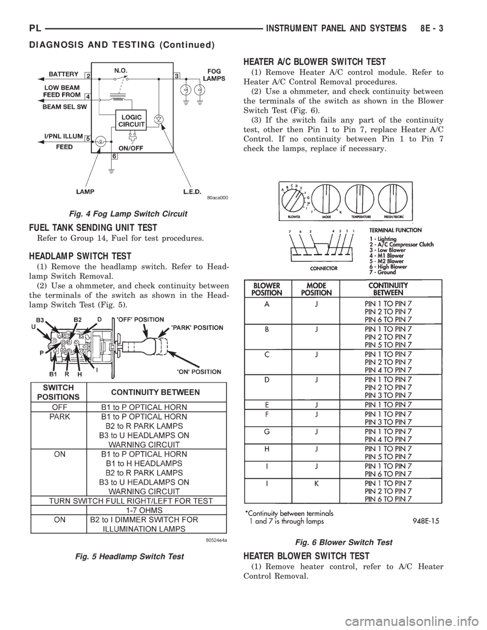
(1) Remove the headlamp switch. Refer to Head-
lamp Switch Removal.
(2) Use a ohmmeter, and check continuity between
the terminals of the switch as shown in the Head-
lamp Switch Test (Fig. 5).
HEATER A/C BLOWER SWITCH TEST
(1) Remove Heater A/C control module. Refer to
Heater A/C Control Removal procedures.
(2) Use a ohmmeter, and check continuity between
the terminals of the switch as shown in the Blower
Switch Test (Fig. 6).
(3) If the switch fails any part of the continuity
test, other then Pin 1 to Pin 7, replace Heater A/C
Control. If no continuity between Pin 1 to Pin 7
check the lamps, replace if necessary.
HEATER BLOWER SWITCH TEST
(1) Remove heater control, refer to A/C Heater
Control Removal.
Fig. 4 Fog Lamp Switch Circuit
Fig. 5 Headlamp Switch Test
Fig. 6 Blower Switch Test
PLINSTRUMENT PANEL AND SYSTEMS 8E - 3
DIAGNOSIS AND TESTING (Continued)
Page 278 of 1200
GLOVE BOX SWITCH/LAMP
REMOVAL
(1) Disconnect battery negative cable and isolate it
or remove fuse 12 prior to removing the switch, or
wires may short to ground.
(2) Open the glove box and push the glove box
sides inward allowing the door bumpers to clear and
the box to tip rearward.
(3) Reach inside the opening and squeeze the
lamp/switch retainers until they are disengage.
(4) Pull the switch/lamp rearward and remove it.
Replace the lamp. To replace the switch disconnect
wire and replace the switch.
INSTALLATION
For installation, reverse the above procedures.
HEADLAMP SWITCH
REMOVAL
(1) Remove the steering column cover and liner.
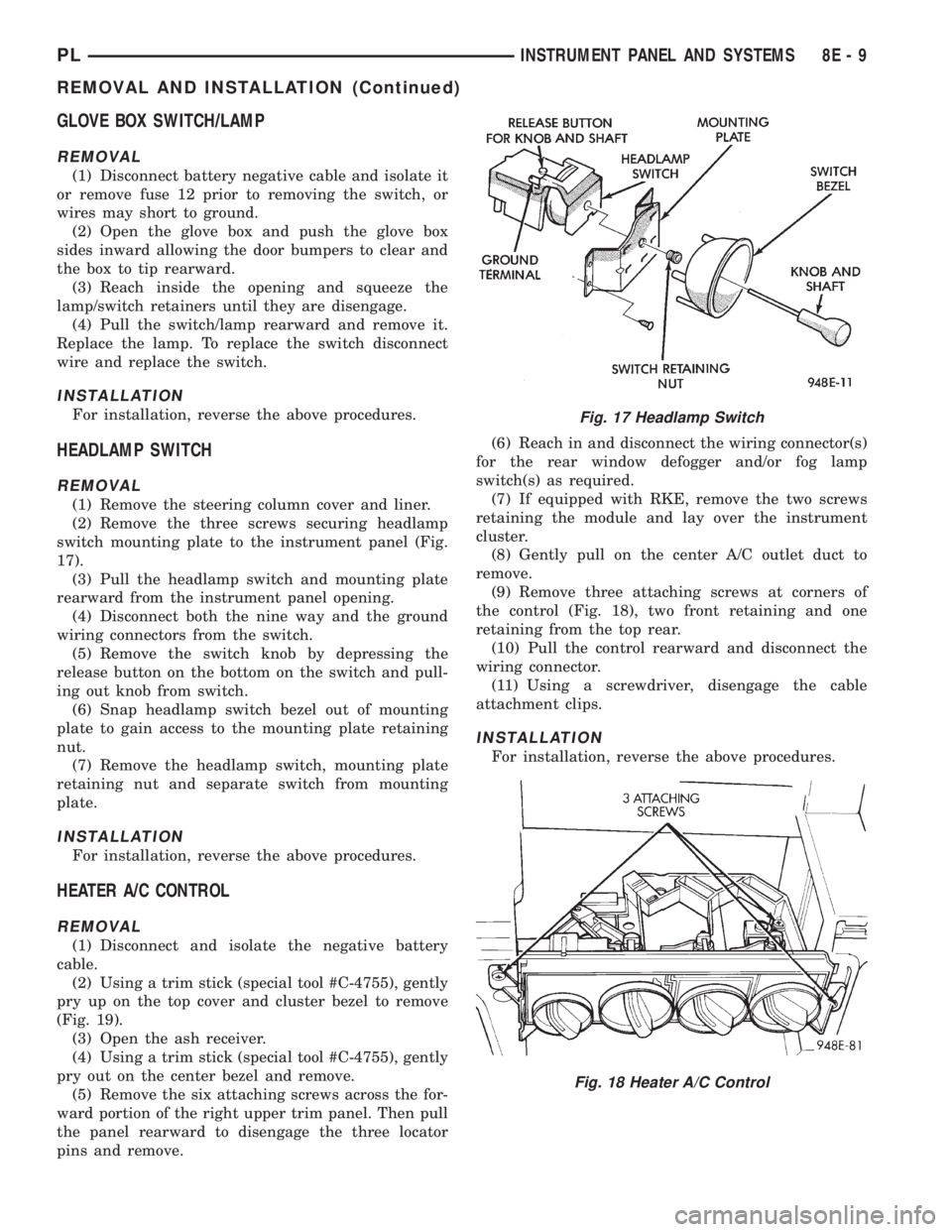
(2) Remove the three screws securing headlamp
switch mounting plate to the instrument panel (Fig.
17).
(3) Pull the headlamp switch and mounting plate
rearward from the instrument panel opening.
(4) Disconnect both the nine way and the ground
wiring connectors from the switch.
(5) Remove the switch knob by depressing the
release button on the bottom on the switch and pull-
ing out knob from switch.
(6) Snap headlamp switch bezel out of mounting
plate to gain access to the mounting plate retaining
nut.
(7) Remove the headlamp switch, mounting plate
retaining nut and separate switch from mounting
plate.
INSTALLATION
For installation, reverse the above procedures.
HEATER A/C CONTROL
REMOVAL
(1) Disconnect and isolate the negative battery
cable.
(2) Using a trim stick (special tool #C-4755), gently
pry up on the top cover and cluster bezel to remove
(Fig. 19).
(3) Open the ash receiver.
(4) Using a trim stick (special tool #C-4755), gently
pry out on the center bezel and remove.
(5) Remove the six attaching screws across the for-
ward portion of the right upper trim panel. Then pull
the panel rearward to disengage the three locator
pins and remove.(6) Reach in and disconnect the wiring connector(s)
for the rear window defogger and/or fog lamp
switch(s) as required.
(7) If equipped with RKE, remove the two screws
retaining the module and lay over the instrument
cluster.
(8) Gently pull on the center A/C outlet duct to
remove.
(9) Remove three attaching screws at corners of
the control (Fig. 18), two front retaining and one
retaining from the top rear.
(10) Pull the control rearward and disconnect the
wiring connector.
(11) Using a screwdriver, disengage the cable
attachment clips.
INSTALLATION
For installation, reverse the above procedures.
Fig. 17 Headlamp Switch
Fig. 18 Heater A/C Control
PLINSTRUMENT PANEL AND SYSTEMS 8E - 9
REMOVAL AND INSTALLATION (Continued)
Page 284 of 1200
INSTRUMENT PANEL AND SYSTEMS
CONTENTS
page page
DIAGNOSIS AND TESTING
FOG LAMP SWITCH TEST................ 1
HEADLAMP LEVELING SWITCH........... 1
INSTRUMENT PANEL AND COMPONENTS . . . 2
REMOVAL AND INSTALLATION
END CAP RHD ......................... 2FRONT FOG LAMP SWITCH.............. 2
HEADLAMP LEVELING SWITCH........... 3
REAR WINDOW DEFOGGER AND/OR REAR
FOG LAMP SWITCH................... 3
DIAGNOSIS AND TESTING
FOG LAMP SWITCH TEST
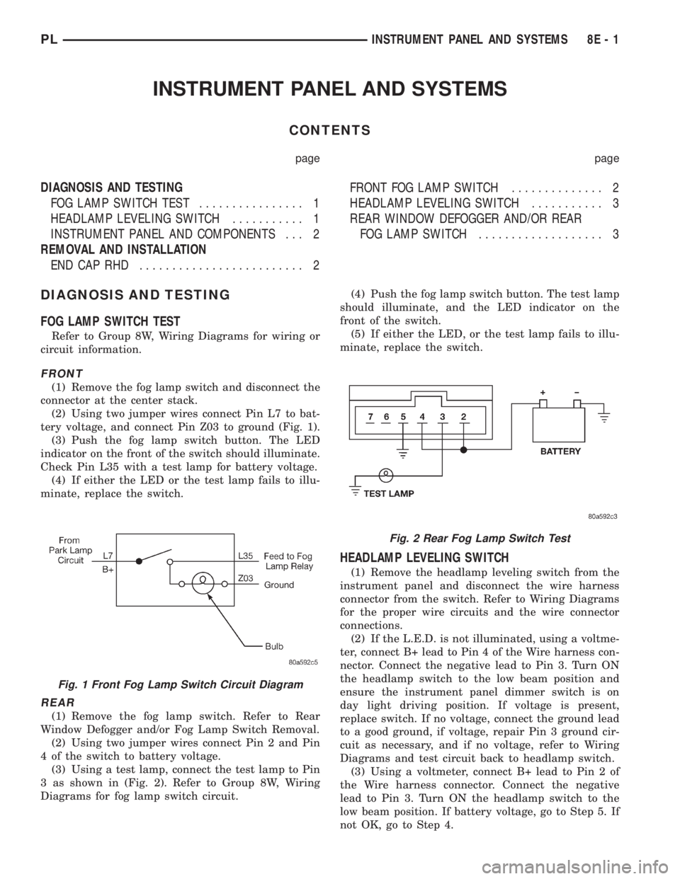
Refer to Group 8W, Wiring Diagrams for wiring or
circuit information.
FRONT
(1) Remove the fog lamp switch and disconnect the
connector at the center stack.
(2) Using two jumper wires connect Pin L7 to bat-
tery voltage, and connect Pin Z03 to ground (Fig. 1).
(3) Push the fog lamp switch button. The LED
indicator on the front of the switch should illuminate.
Check Pin L35 with a test lamp for battery voltage.
(4) If either the LED or the test lamp fails to illu-
minate, replace the switch.
REAR
(1) Remove the fog lamp switch. Refer to Rear
Window Defogger and/or Fog Lamp Switch Removal.
(2) Using two jumper wires connect Pin 2 and Pin
4 of the switch to battery voltage.
(3) Using a test lamp, connect the test lamp to Pin
3 as shown in (Fig. 2). Refer to Group 8W, Wiring
Diagrams for fog lamp switch circuit.(4) Push the fog lamp switch button. The test lamp
should illuminate, and the LED indicator on the
front of the switch.
(5) If either the LED, or the test lamp fails to illu-
minate, replace the switch.
HEADLAMP LEVELING SWITCH
(1) Remove the headlamp leveling switch from the
instrument panel and disconnect the wire harness
connector from the switch. Refer to Wiring Diagrams
for the proper wire circuits and the wire connector
connections.
(2) If the L.E.D. is not illuminated, using a voltme-
ter, connect B+ lead to Pin 4 of the Wire harness con-
nector. Connect the negative lead to Pin 3. Turn ON
the headlamp switch to the low beam position and
ensure the instrument panel dimmer switch is on
day light driving position. If voltage is present,
replace switch. If no voltage, connect the ground lead
to a good ground, if voltage, repair Pin 3 ground cir-
cuit as necessary, and if no voltage, refer to Wiring
Diagrams and test circuit back to headlamp switch.
(3) Using a voltmeter, connect B+ lead to Pin 2 of
the Wire harness connector. Connect the negative
lead to Pin 3. Turn ON the headlamp switch to the
low beam position. If battery voltage, go to Step 5. If
not OK, go to Step 4.
Fig. 1 Front Fog Lamp Switch Circuit Diagram
Fig. 2 Rear Fog Lamp Switch Test
PLINSTRUMENT PANEL AND SYSTEMS 8E - 1
Page 285 of 1200
(4) Connect the ground lead to a good ground, if no
voltage, refer to Wiring Diagrams and test circuit
back to headlamp switch. If battery voltage, repair
Pin 3 ground circuit as necessary.
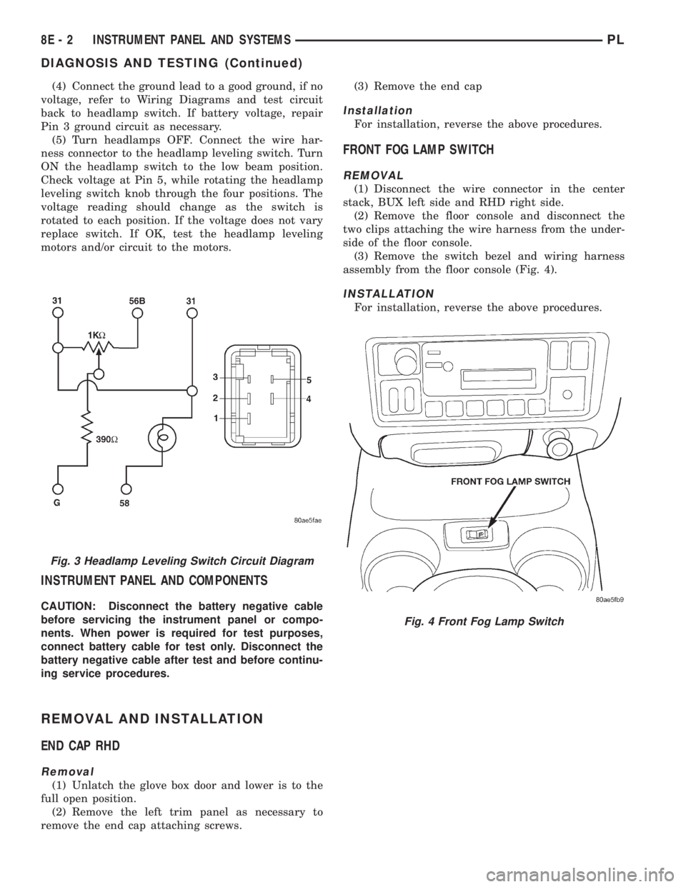
(5) Turn headlamps OFF. Connect the wire har-
ness connector to the headlamp leveling switch. Turn
ON the headlamp switch to the low beam position.
Check voltage at Pin 5, while rotating the headlamp
leveling switch knob through the four positions. The
voltage reading should change as the switch is
rotated to each position. If the voltage does not vary
replace switch. If OK, test the headlamp leveling
motors and/or circuit to the motors.
INSTRUMENT PANEL AND COMPONENTS
CAUTION: Disconnect the battery negative cable
before servicing the instrument panel or compo-
nents. When power is required for test purposes,
connect battery cable for test only. Disconnect the
battery negative cable after test and before continu-
ing service procedures.
REMOVAL AND INSTALLATION
END CAP RHD
Removal
(1) Unlatch the glove box door and lower is to the
full open position.
(2) Remove the left trim panel as necessary to
remove the end cap attaching screws.(3) Remove the end cap
Installation
For installation, reverse the above procedures.
FRONT FOG LAMP SWITCH
REMOVAL
(1) Disconnect the wire connector in the center
stack, BUX left side and RHD right side.
(2) Remove the floor console and disconnect the
two clips attaching the wire harness from the under-
side of the floor console.
(3) Remove the switch bezel and wiring harness
assembly from the floor console (Fig. 4).
INSTALLATION
For installation, reverse the above procedures.
Fig. 3 Headlamp Leveling Switch Circuit Diagram
Fig. 4 Front Fog Lamp Switch
8E - 2 INSTRUMENT PANEL AND SYSTEMSPL
DIAGNOSIS AND TESTING (Continued)
Page 286 of 1200
HEADLAMP LEVELING SWITCH
REMOVAL
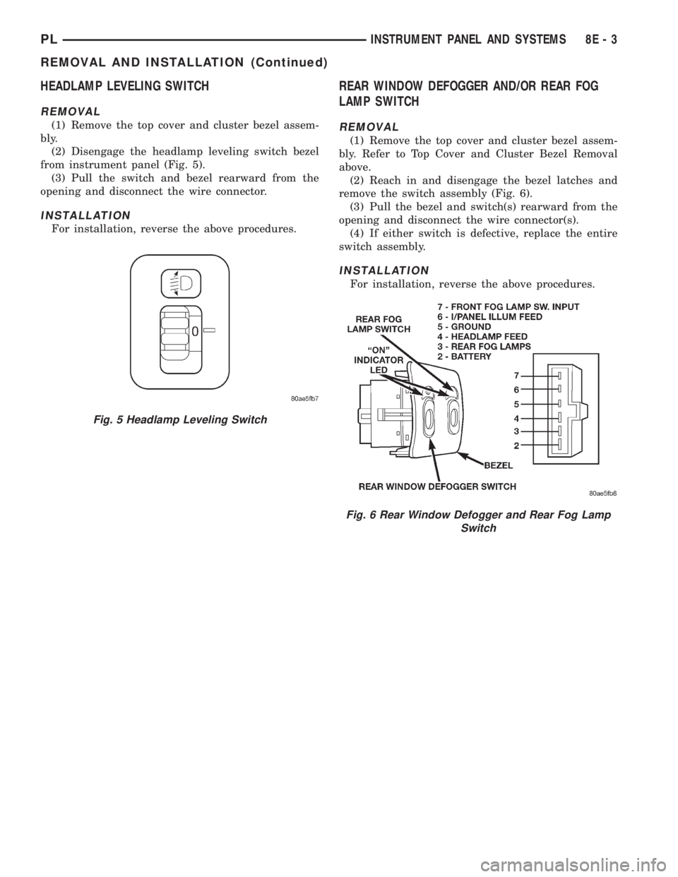
(1) Remove the top cover and cluster bezel assem-
bly.
(2) Disengage the headlamp leveling switch bezel
from instrument panel (Fig. 5).
(3) Pull the switch and bezel rearward from the
opening and disconnect the wire connector.
INSTALLATION
For installation, reverse the above procedures.
REAR WINDOW DEFOGGER AND/OR REAR FOG
LAMP SWITCH
REMOVAL
(1) Remove the top cover and cluster bezel assem-
bly. Refer to Top Cover and Cluster Bezel Removal
above.
(2) Reach in and disengage the bezel latches and
remove the switch assembly (Fig. 6).
(3) Pull the bezel and switch(s) rearward from the
opening and disconnect the wire connector(s).
(4) If either switch is defective, replace the entire
switch assembly.
INSTALLATION
For installation, reverse the above procedures.
Fig. 5 Headlamp Leveling Switch
Fig. 6 Rear Window Defogger and Rear Fog Lamp
Switch
PLINSTRUMENT PANEL AND SYSTEMS 8E - 3
REMOVAL AND INSTALLATION (Continued)
Page 294 of 1200
HORNS
CONTENTS
page page
DESCRIPTION AND OPERATION
INTRODUCTION......................... 1
DIAGNOSIS AND TESTING
HORN RELAY........................... 2
HORN SWITCH.......................... 2
HORN................................. 1SYSTEM TEST.......................... 2
REMOVAL AND INSTALLATION
HORN RELAY........................... 4
HORN SWITCHES........................ 4
HORN................................. 4
DESCRIPTION AND OPERATION
INTRODUCTION
WARNING: ON VEHICLES EQUIPPED WITH AIR-
BAG, SEE GROUP 8M, RESTRAINT SYSTEMS FOR
STEERING WHEEL OR COLUMN REMOVAL PROCE-
DURES.
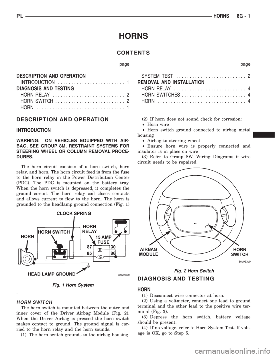
The horn circuit consists of a horn switch, horn
relay, and horn. The horn circuit feed is from the fuse
to the horn relay in the Power Distribution Center
(PDC). The PDC is mounted on the battery tray.
When the horn switch is depressed, it completes the
ground circuit. The horn relay coil closes contacts
and allows current to flow to the horn. The horn is
grounded to the headlamp ground connection (Fig. 1)
.
HORN SWITCH
The horn switch is mounted between the outer and
inner cover of the Driver Airbag Module (Fig. 2).
When the Driver Airbag is pressed the horn switch
makes contact to ground. The ground signal is car-
ried to the horn relay and the horn sounds.
(1) The horn switch grounds to the airbag housing.(2) If horn does not sound check for corrosion:
²Horn wire
²Horn switch ground connected to airbag metal
housing
²Airbag to steering wheel
²Ensure horn wire is properly connected and
insulator is in place on wire
(3) Refer to Group 8W, Wiring Diagrams if wire
circuit needs to be repaired.
DIAGNOSIS AND TESTING
HORN
(1) Disconnect wire connector at horn.
(2) Using a voltmeter, connect one lead to ground
terminal and the other lead to the positive wire ter-
minal (Fig. 3).
(3) Depress the horn switch, battery voltage
should be present.
(4) If no voltage, refer to Horn System Test. If volt-
age is OK, go to Step 5.
Fig. 1 Horn System
Fig. 2 Horn Switch
PLHORNS 8G - 1
Page 310 of 1200
TURN SIGNAL AND FLASHERS
CONTENTS
page page
GENERAL INFORMATION
INTRODUCTION......................... 1
DESCRIPTION AND OPERATION
COMBINATION FLASHER.................. 1
HAZARD WARNING SYSTEM............... 1DIAGNOSIS AND TESTING
MULTI-FUNCTION SWITCH................ 2
MULTI-FUNCTION SWITCH TEST............ 2
REMOVAL AND INSTALLATION
MULTI-FUNCTION SWITCH................ 4
GENERAL INFORMATION
INTRODUCTION
WARNING: ON VEHICLES EQUIPPED WITH AIR-
BAG, SEE GROUP 8M, RESTRAINT SYSTEMS FOR
AIRBAG REMOVAL PROCEDURES.
The turn signals are part of the multi-function
switch. Which contains:
²Electrical circuitry for turn signals
²Hazard warning switch
²Headlamp beam select switch
²Headlamp optical horn
The integrated switch assembly is mounted to the
left hand side of the steering column. When the
driver wishes to signal his intentions to change direc-
tion of travel, he moves the lever upward to cause
the right signals to flash and downward to cause the
left signals to flash. After completion of a turn the
system is deactivated automatically. As the steering
wheel returns to the straight ahead position, a can-
celing cam molded to the clockspring mechanism
comes in contact with the cancel actuator on the turn
signal multi-function switch assembly. The cam lobe,
pushing on the cancel actuator, returns the switch to
the off position.
If only momentary signaling such as indication of a
lane change is desired, the switch is actuated to a
left or right intermediate detent position. In this
position the signal lamps flash as described above,
but the switch returns to the OFF position as soon as
the lever is released.
When the system is activated, one of two indicator
lamps mounted in the instrument cluster flashes in
unison with the turn signal lamps, indicating to the
driver that the system is operating.
DESCRIPTION AND OPERATION
HAZARD WARNING SYSTEM
The hazard warning system is actuated by a slide
button located on the top of the steering column
between the steering wheel and the instrument
panel. The hazard switch is identified with a double
triangle on front of the button.
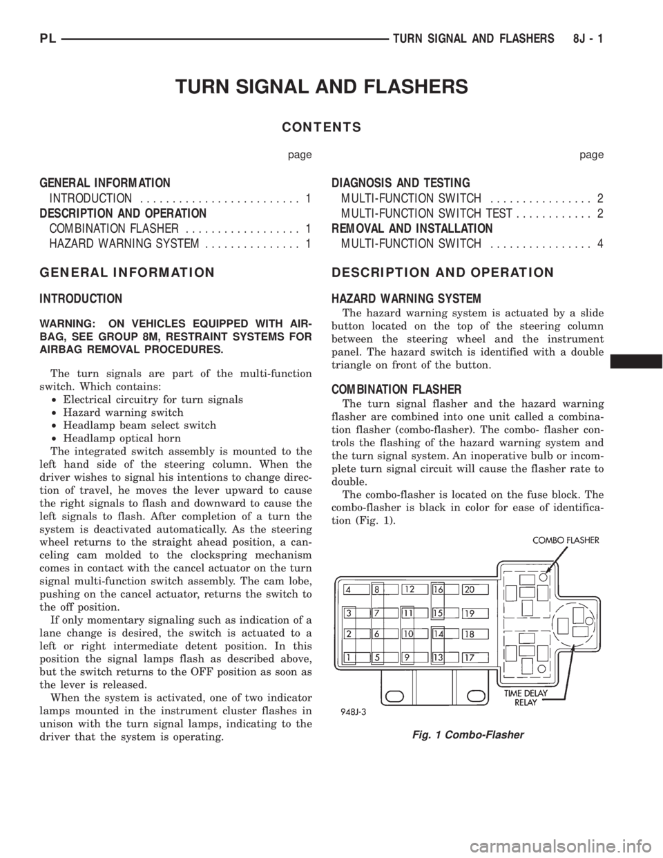
COMBINATION FLASHER
The turn signal flasher and the hazard warning
flasher are combined into one unit called a combina-
tion flasher (combo-flasher). The combo- flasher con-
trols the flashing of the hazard warning system and
the turn signal system. An inoperative bulb or incom-
plete turn signal circuit will cause the flasher rate to
double.
The combo-flasher is located on the fuse block. The
combo-flasher is black in color for ease of identifica-
tion (Fig. 1).
Fig. 1 Combo-Flasher
PLTURN SIGNAL AND FLASHERS 8J - 1
Page 311 of 1200
DIAGNOSIS AND TESTING
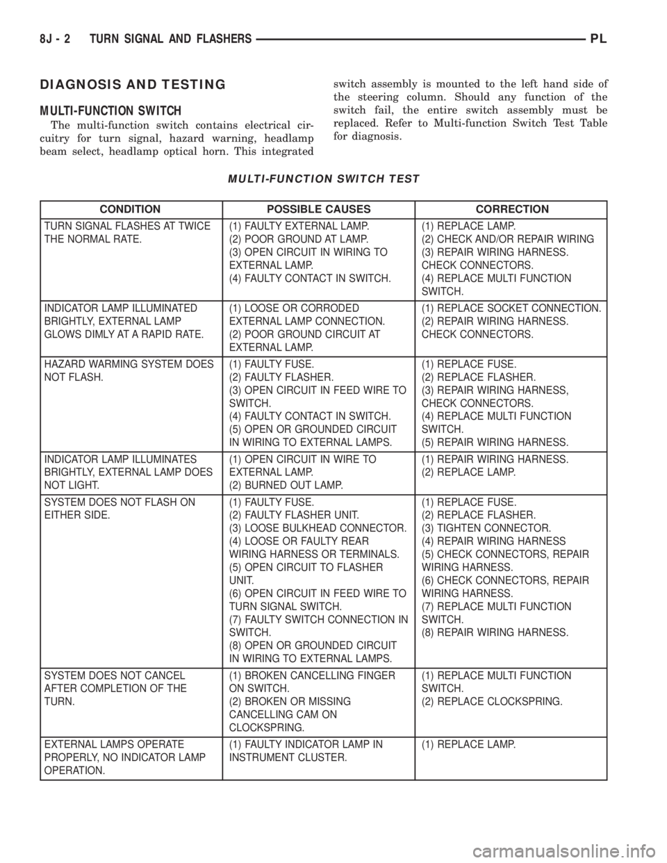
MULTI-FUNCTION SWITCH
The multi-function switch contains electrical cir-
cuitry for turn signal, hazard warning, headlamp
beam select, headlamp optical horn. This integratedswitch assembly is mounted to the left hand side of
the steering column. Should any function of the
switch fail, the entire switch assembly must be
replaced. Refer to Multi-function Switch Test Table
for diagnosis.
MULTI-FUNCTION SWITCH TEST
CONDITION POSSIBLE CAUSES CORRECTION
TURN SIGNAL FLASHES AT TWICE
THE NORMAL RATE.(1) FAULTY EXTERNAL LAMP.
(2) POOR GROUND AT LAMP.
(3) OPEN CIRCUIT IN WIRING TO
EXTERNAL LAMP.
(4) FAULTY CONTACT IN SWITCH.(1) REPLACE LAMP.
(2) CHECK AND/OR REPAIR WIRING
(3) REPAIR WIRING HARNESS.
CHECK CONNECTORS.
(4) REPLACE MULTI FUNCTION
SWITCH.
INDICATOR LAMP ILLUMINATED
BRIGHTLY, EXTERNAL LAMP
GLOWS DIMLY AT A RAPID RATE.(1) LOOSE OR CORRODED
EXTERNAL LAMP CONNECTION.
(2) POOR GROUND CIRCUIT AT
EXTERNAL LAMP.(1) REPLACE SOCKET CONNECTION.
(2) REPAIR WIRING HARNESS.
CHECK CONNECTORS.
HAZARD WARMING SYSTEM DOES
NOT FLASH.(1) FAULTY FUSE.
(2) FAULTY FLASHER.
(3) OPEN CIRCUIT IN FEED WIRE TO
SWITCH.
(4) FAULTY CONTACT IN SWITCH.
(5) OPEN OR GROUNDED CIRCUIT
IN WIRING TO EXTERNAL LAMPS.(1) REPLACE FUSE.
(2) REPLACE FLASHER.
(3) REPAIR WIRING HARNESS,
CHECK CONNECTORS.
(4) REPLACE MULTI FUNCTION
SWITCH.
(5) REPAIR WIRING HARNESS.
INDICATOR LAMP ILLUMINATES
BRIGHTLY, EXTERNAL LAMP DOES
NOT LIGHT.(1) OPEN CIRCUIT IN WIRE TO
EXTERNAL LAMP.
(2) BURNED OUT LAMP.(1) REPAIR WIRING HARNESS.
(2) REPLACE LAMP.
SYSTEM DOES NOT FLASH ON
EITHER SIDE.(1) FAULTY FUSE.
(2) FAULTY FLASHER UNIT.
(3) LOOSE BULKHEAD CONNECTOR.
(4) LOOSE OR FAULTY REAR
WIRING HARNESS OR TERMINALS.
(5) OPEN CIRCUIT TO FLASHER
UNIT.
(6) OPEN CIRCUIT IN FEED WIRE TO
TURN SIGNAL SWITCH.
(7) FAULTY SWITCH CONNECTION IN
SWITCH.
(8) OPEN OR GROUNDED CIRCUIT
IN WIRING TO EXTERNAL LAMPS.(1) REPLACE FUSE.
(2) REPLACE FLASHER.
(3) TIGHTEN CONNECTOR.
(4) REPAIR WIRING HARNESS
(5) CHECK CONNECTORS, REPAIR
WIRING HARNESS.
(6) CHECK CONNECTORS, REPAIR
WIRING HARNESS.
(7) REPLACE MULTI FUNCTION
SWITCH.
(8) REPAIR WIRING HARNESS.
SYSTEM DOES NOT CANCEL
AFTER COMPLETION OF THE
TURN.(1) BROKEN CANCELLING FINGER
ON SWITCH.
(2) BROKEN OR MISSING
CANCELLING CAM ON
CLOCKSPRING.(1) REPLACE MULTI FUNCTION
SWITCH.
(2) REPLACE CLOCKSPRING.
EXTERNAL LAMPS OPERATE
PROPERLY, NO INDICATOR LAMP
OPERATION.(1) FAULTY INDICATOR LAMP IN
INSTRUMENT CLUSTER.(1) REPLACE LAMP.
8J - 2 TURN SIGNAL AND FLASHERSPL