wiring DODGE NEON 1999 Service Repair Manual
[x] Cancel search | Manufacturer: DODGE, Model Year: 1999, Model line: NEON, Model: DODGE NEON 1999Pages: 1200, PDF Size: 35.29 MB
Page 122 of 1200
MASTER CYLINDER
REMOVE
CAUTION: On ABS equipped vehicles, vacuum in
power booster must be pumped down before
removing master cylinder to prevent booster from
sucking in any contamination. This can be done
simply by pumping the brake pedal until a firm
pedal is achieved, with the ignition off.
(1) On ABS equipped vehicles, be sure engine is
not running, and pump the brake pedal until a firm
pedal is achieved (4-5 strokes).
(2) Remove vehicle wiring harness connector, from
brake fluid level sensor, in master cylinder brake
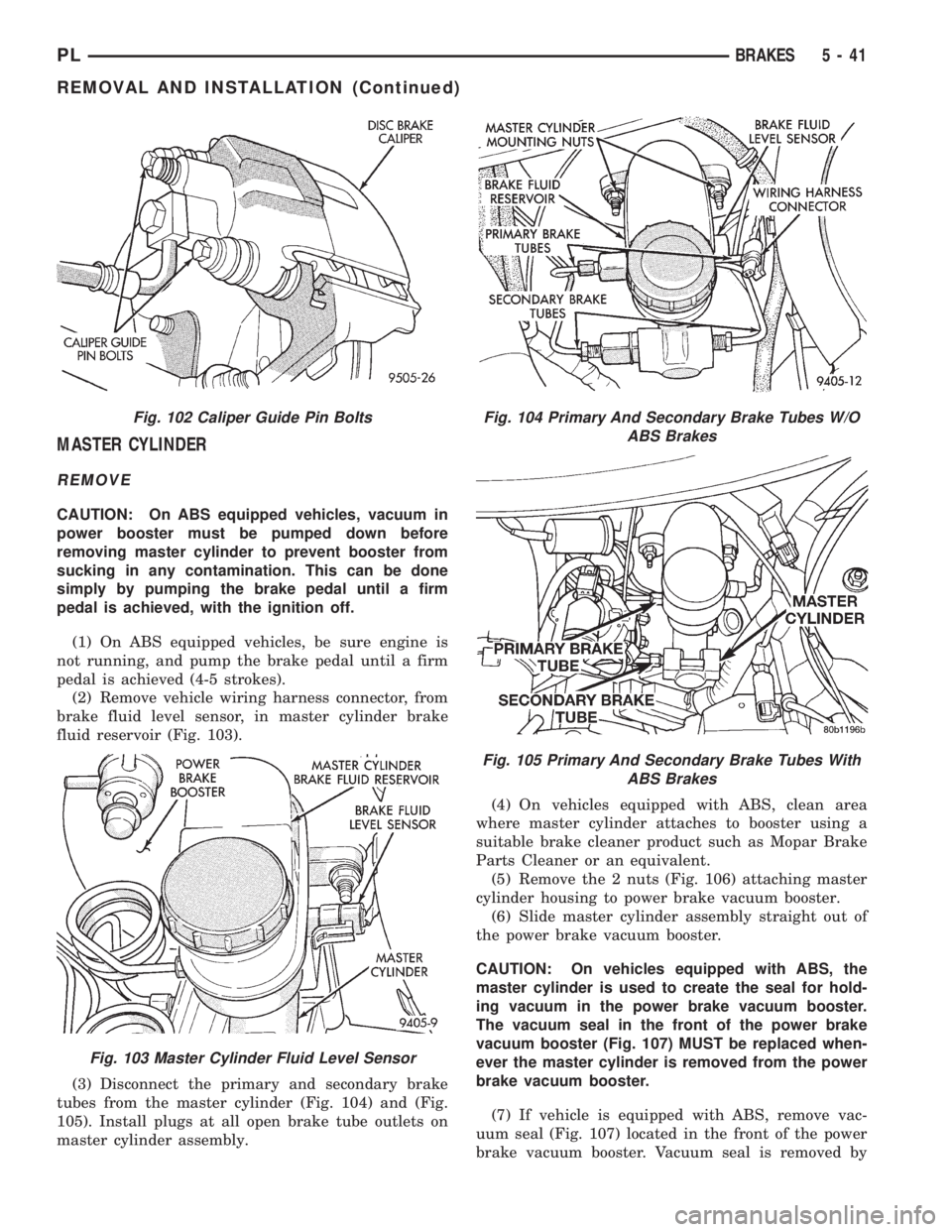
fluid reservoir (Fig. 103).
(3) Disconnect the primary and secondary brake
tubes from the master cylinder (Fig. 104) and (Fig.
105). Install plugs at all open brake tube outlets on
master cylinder assembly.(4) On vehicles equipped with ABS, clean area
where master cylinder attaches to booster using a
suitable brake cleaner product such as Mopar Brake
Parts Cleaner or an equivalent.
(5) Remove the 2 nuts (Fig. 106) attaching master
cylinder housing to power brake vacuum booster.
(6) Slide master cylinder assembly straight out of
the power brake vacuum booster.
CAUTION: On vehicles equipped with ABS, the
master cylinder is used to create the seal for hold-
ing vacuum in the power brake vacuum booster.
The vacuum seal in the front of the power brake
vacuum booster (Fig. 107) MUST be replaced when-
ever the master cylinder is removed from the power
brake vacuum booster.
(7) If vehicle is equipped with ABS, remove vac-
uum seal (Fig. 107) located in the front of the power
brake vacuum booster. Vacuum seal is removed by
Fig. 102 Caliper Guide Pin Bolts
Fig. 103 Master Cylinder Fluid Level Sensor
Fig. 104 Primary And Secondary Brake Tubes W/O
ABS Brakes
Fig. 105 Primary And Secondary Brake Tubes With
ABS Brakes
PLBRAKES 5 - 41
REMOVAL AND INSTALLATION (Continued)
Page 125 of 1200
VACUUM BOOSTER
REMOVE
CAUTION: On ABS equipped vehicles, vacuum in
power booster must be pumped down before
removing master cylinder to prevent booster from
sucking in any contamination. This can be done
simply by pumping the brake pedal until a firm
pedal is achieved, with the ignition off.
(1) On ABS equipped vehicles, with engine not
running, pump the brake pedal until a firm pedal is
achieved (4-5 strokes).
(2) Remove vehicle wiring harness connector from
brake fluid level sensor located in master cylinder
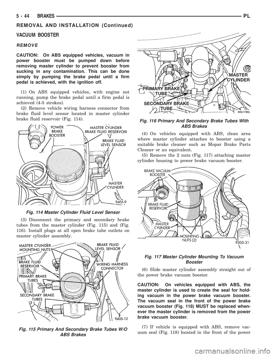
brake fluid reservoir (Fig. 114).
(3) Disconnect the primary and secondary brake
tubes from the master cylinder (Fig. 115) and (Fig.
116). Install plugs at all open brake tube outlets on
master cylinder assembly.(4) On vehicles equipped with ABS, clean area
where master cylinder attaches to booster using a
suitable brake cleaner such as Mopar Brake Parts
Cleaner or an equivalent.
(5) Remove the 2 nuts (Fig. 117) attaching master
cylinder housing to power brake vacuum booster.
(6) Slide master cylinder assembly straight out of
the power brake vacuum booster.
CAUTION: On vehicles equipped with ABS, the
master cylinder is used to create the seal for hold-
ing vacuum in the power brake vacuum booster.
The vacuum seal in the front of the power brake
vacuum booster (Fig. 118) MUST be replaced when-
ever the master cylinder is removed from the power
brake vacuum booster.
(7) If vehicle is equipped with ABS, remove vac-
uum seal (Fig. 118) located in the front of the power
Fig. 114 Master Cylinder Fluid Level Sensor
Fig. 115 Primary And Secondary Brake Tubes W/O
ABS Brakes
Fig. 116 Primary And Secondary Brake Tubes With
ABS Brakes
Fig. 117 Master Cylinder Mounting To Vacuum
Booster
5 - 44 BRAKESPL
REMOVAL AND INSTALLATION (Continued)
Page 128 of 1200
(9) Position master cylinder on studs of power
brake unit, aligning push rod on power brake vac-
uum booster with master cylinder push rod.
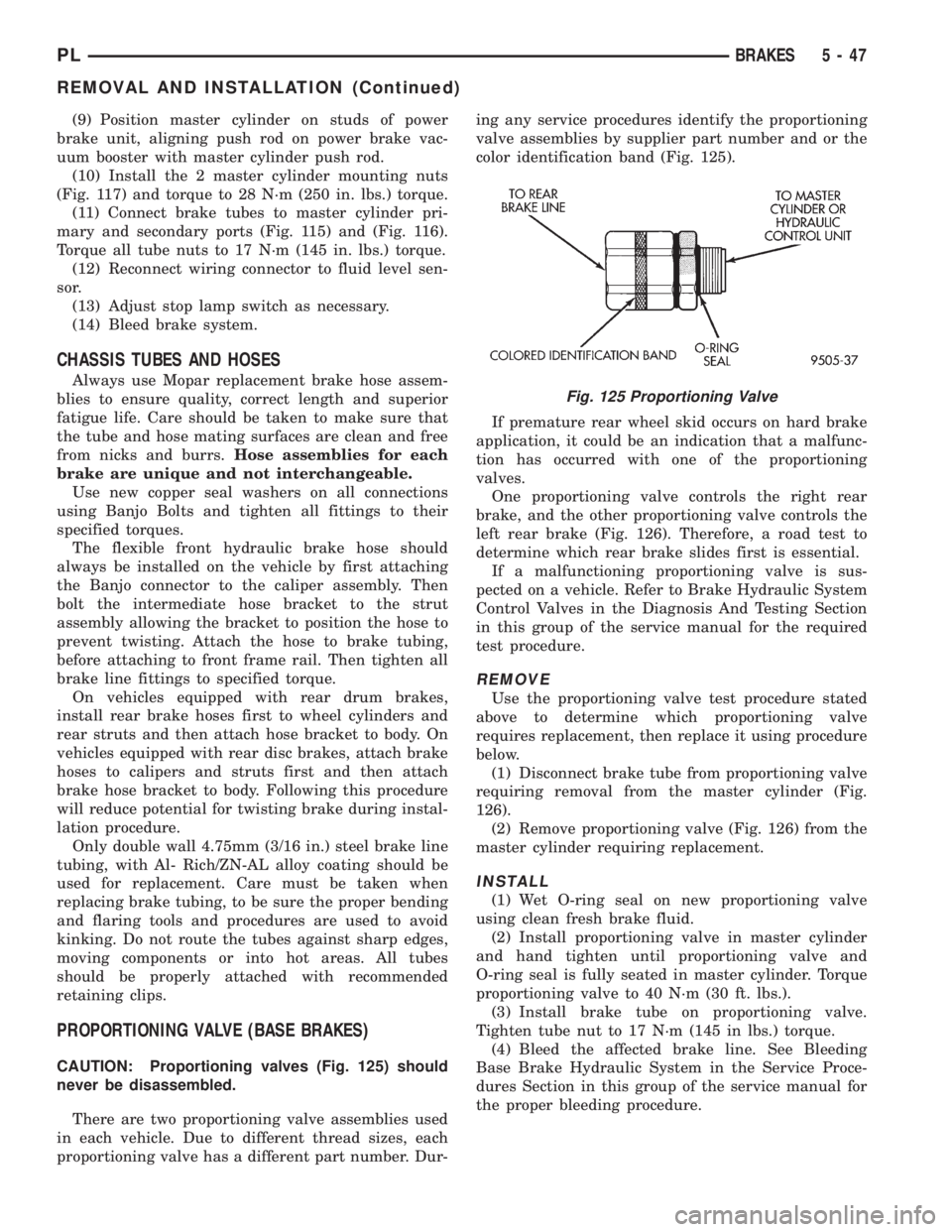
(10) Install the 2 master cylinder mounting nuts
(Fig. 117) and torque to 28 N´m (250 in. lbs.) torque.
(11) Connect brake tubes to master cylinder pri-
mary and secondary ports (Fig. 115) and (Fig. 116).
Torque all tube nuts to 17 N´m (145 in. lbs.) torque.
(12) Reconnect wiring connector to fluid level sen-
sor.
(13) Adjust stop lamp switch as necessary.
(14) Bleed brake system.
CHASSIS TUBES AND HOSES
Always use Mopar replacement brake hose assem-
blies to ensure quality, correct length and superior
fatigue life. Care should be taken to make sure that
the tube and hose mating surfaces are clean and free
from nicks and burrs.Hose assemblies for each
brake are unique and not interchangeable.
Use new copper seal washers on all connections
using Banjo Bolts and tighten all fittings to their
specified torques.
The flexible front hydraulic brake hose should
always be installed on the vehicle by first attaching
the Banjo connector to the caliper assembly. Then
bolt the intermediate hose bracket to the strut
assembly allowing the bracket to position the hose to
prevent twisting. Attach the hose to brake tubing,
before attaching to front frame rail. Then tighten all
brake line fittings to specified torque.
On vehicles equipped with rear drum brakes,
install rear brake hoses first to wheel cylinders and
rear struts and then attach hose bracket to body. On
vehicles equipped with rear disc brakes, attach brake
hoses to calipers and struts first and then attach
brake hose bracket to body. Following this procedure
will reduce potential for twisting brake during instal-
lation procedure.
Only double wall 4.75mm (3/16 in.) steel brake line
tubing, with Al- Rich/ZN-AL alloy coating should be
used for replacement. Care must be taken when
replacing brake tubing, to be sure the proper bending
and flaring tools and procedures are used to avoid
kinking. Do not route the tubes against sharp edges,
moving components or into hot areas. All tubes
should be properly attached with recommended
retaining clips.
PROPORTIONING VALVE (BASE BRAKES)
CAUTION: Proportioning valves (Fig. 125) should
never be disassembled.
There are two proportioning valve assemblies used
in each vehicle. Due to different thread sizes, each
proportioning valve has a different part number. Dur-ing any service procedures identify the proportioning
valve assemblies by supplier part number and or the
color identification band (Fig. 125).
If premature rear wheel skid occurs on hard brake
application, it could be an indication that a malfunc-
tion has occurred with one of the proportioning
valves.
One proportioning valve controls the right rear
brake, and the other proportioning valve controls the
left rear brake (Fig. 126). Therefore, a road test to
determine which rear brake slides first is essential.
If a malfunctioning proportioning valve is sus-
pected on a vehicle. Refer to Brake Hydraulic System
Control Valves in the Diagnosis And Testing Section
in this group of the service manual for the required
test procedure.
REMOVE
Use the proportioning valve test procedure stated
above to determine which proportioning valve
requires replacement, then replace it using procedure
below.
(1) Disconnect brake tube from proportioning valve
requiring removal from the master cylinder (Fig.
126).
(2) Remove proportioning valve (Fig. 126) from the
master cylinder requiring replacement.
INSTALL
(1) Wet O-ring seal on new proportioning valve
using clean fresh brake fluid.
(2) Install proportioning valve in master cylinder
and hand tighten until proportioning valve and
O-ring seal is fully seated in master cylinder. Torque
proportioning valve to 40 N´m (30 ft. lbs.).
(3) Install brake tube on proportioning valve.
Tighten tube nut to 17 N´m (145 in lbs.) torque.
(4) Bleed the affected brake line. See Bleeding
Base Brake Hydraulic System in the Service Proce-
dures Section in this group of the service manual for
the proper bleeding procedure.
Fig. 125 Proportioning Valve
PLBRAKES 5 - 47
REMOVAL AND INSTALLATION (Continued)
Page 130 of 1200
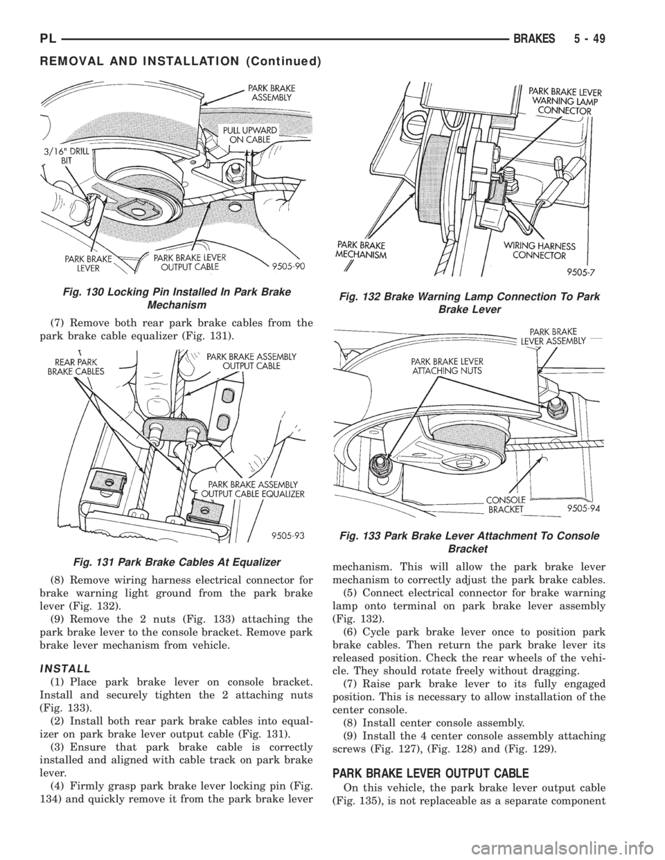
(7) Remove both rear park brake cables from the
park brake cable equalizer (Fig. 131).
(8) Remove wiring harness electrical connector for
brake warning light ground from the park brake
lever (Fig. 132).
(9) Remove the 2 nuts (Fig. 133) attaching the
park brake lever to the console bracket. Remove park
brake lever mechanism from vehicle.
INSTALL
(1) Place park brake lever on console bracket.
Install and securely tighten the 2 attaching nuts
(Fig. 133).
(2) Install both rear park brake cables into equal-
izer on park brake lever output cable (Fig. 131).
(3) Ensure that park brake cable is correctly
installed and aligned with cable track on park brake
lever.
(4) Firmly grasp park brake lever locking pin (Fig.
134) and quickly remove it from the park brake levermechanism. This will allow the park brake lever
mechanism to correctly adjust the park brake cables.
(5) Connect electrical connector for brake warning
lamp onto terminal on park brake lever assembly
(Fig. 132).
(6) Cycle park brake lever once to position park
brake cables. Then return the park brake lever its
released position. Check the rear wheels of the vehi-
cle. They should rotate freely without dragging.
(7) Raise park brake lever to its fully engaged
position. This is necessary to allow installation of the
center console.
(8) Install center console assembly.
(9) Install the 4 center console assembly attaching
screws (Fig. 127), (Fig. 128) and (Fig. 129).
PARK BRAKE LEVER OUTPUT CABLE
On this vehicle, the park brake lever output cable
(Fig. 135), is not replaceable as a separate component
Fig. 130 Locking Pin Installed In Park Brake
Mechanism
Fig. 131 Park Brake Cables At Equalizer
Fig. 132 Brake Warning Lamp Connection To Park
Brake Lever
Fig. 133 Park Brake Lever Attachment To Console
Bracket
PLBRAKES 5 - 49
REMOVAL AND INSTALLATION (Continued)
Page 138 of 1200
(9) InstallA NEWhub and bearing assembly
retaining nut. Torque the hub and bearing assembly
retaining nut to 168 N´m (124 ft. lbs.).
(10) Install hub and bearing assembly dust cap.
(11) Install rear rotor.
(12) Install rear disc brake caliper on the adapter
(See Brake Shoe Removal).
(13) Install wheel and tire assemblies.
(14) Tighten wheel stud nuts to 129 N´m (95
ft.lbs.).
STOP LAMP SWITCH
REMOVE
(1) Depress and hold the brake pedal while rotat-
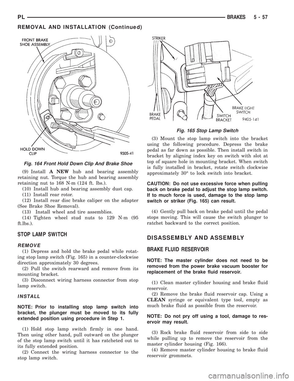
ing stop lamp switch (Fig. 165) in a counter-clockwise
direction approximately 30 degrees.
(2) Pull the switch rearward and remove from its
mounting bracket.
(3) Disconnect wiring harness connector from stop
lamp switch.
INSTALL
NOTE: Prior to installing stop lamp switch into
bracket, the plunger must be moved to its fully
extended position using procedure in Step 1.
(1) Hold stop lamp switch firmly in one hand.
Then using other hand, pull outward on the plunger
of the stop lamp switch until it has ratcheted out to
its fully extended position.
(2) Connect the wiring harness connector to the
stop lamp switch.(3) Mount the stop lamp switch into the bracket
using the following procedure. Depress the brake
pedal as far down as possible. Then install switch in
bracket by aligning index key on switch with slot at
top of square hole in mounting bracket. When switch
is fully installed in bracket, rotate switch clockwise
approximately 30É to lock switch into bracket.
CAUTION: Do not use excessive force when pulling
back on brake pedal to adjust the stop lamp switch.
If to much force is used, damage to the stop lamp
switch or striker (Fig. 165) can result.
(4) Gently pull back on brake pedal until the pedal
stops moving. This will cause the switch plunger to
ratchet backward to the correct position.
DISASSEMBLY AND ASSEMBLY
BRAKE FLUID RESERVOIR
NOTE: The master cylinder does not need to be
removed from the power brake vacuum booster for
replacement of the brake fluid reservoir.
(1) Clean master cylinder housing and brake fluid
reservoir.
(2) Remove the brake fluid reservoir cap. Using a
CLEANsyringe or equivalent type tool, empty as
much brake fluid as possible from the reservoir.
NOTE: Do not pry off using a tool, damage to res-
ervoir may result.
(3) Rock brake fluid reservoir from side to side
while pulling up to remove the reservoir from the
master cylinder housing (Fig. 166).
(4) Remove master cylinder housing to brake fluid
reservoir grommets.
Fig. 164 Front Hold Down Clip And Brake Shoe
Fig. 165 Stop Lamp Switch
PLBRAKES 5 - 57
REMOVAL AND INSTALLATION (Continued)
Page 139 of 1200
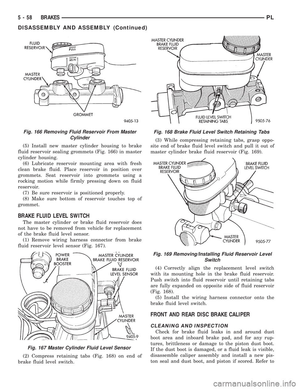
(5) Install new master cylinder housing to brake
fluid reservoir sealing grommets (Fig. 166) in master
cylinder housing.
(6) Lubricate reservoir mounting area with fresh
clean brake fluid. Place reservoir in position over
grommets. Seat reservoir into grommets using a
rocking motion while firmly pressing down on fluid
reservoir.
(7) Be sure reservoir is positioned properly.
(8) Make sure bottom of reservoir touches top of
grommet.
BRAKE FLUID LEVEL SWITCH
The master cylinder or brake fluid reservoir does
not have to be removed from vehicle for replacement
of the brake fluid level sensor.
(1) Remove wiring harness connector from brake
fluid reservoir level sensor (Fig. 167).
(2) Compress retaining tabs (Fig. 168) on end of
brake fluid level switch.(3) While compressing retaining tabs, grasp oppo-
site end of brake fluid level switch and pull it out of
master cylinder brake fluid reservoir (Fig. 169).
(4) Correctly align the replacement level switch
with its mounting hole in the brake fluid reservoir.
Push switch into fluid reservoir until retaining tabs
are fully expanded on opposite side of fluid reservoir
(Fig. 168).
(5) Install the wiring harness connector onto the
brake fluid level switch.
FRONT AND REAR DISC BRAKE CALIPER
CLEANING AND INSPECTION
Check for brake fluid leaks in and around dust
boot area and inboard brake pad, and for any rup-
tures, brittleness or damage to the piston dust boot.
If the dust boot is damaged, or a fluid leak is visible,
disassemble caliper assembly and install a new pis-
ton seal and dust boot, and piston if scored. Refer to
Fig. 166 Removing Fluid Reservoir From Master
Cylinder
Fig. 167 Master Cylinder Fluid Level Sensor
Fig. 168 Brake Fluid Level Switch Retaining Tabs
Fig. 169 Removing/Installing Fluid Reservoir Level
Switch
5 - 58 BRAKESPL
DISASSEMBLY AND ASSEMBLY (Continued)
Page 146 of 1200
If old brake shoe return or hold down springs have
overheated or are damaged, replace. Overheating
indications are paint discoloration or distorted end
coils.
REAR DRUM BRAKE WHEEL CYLINDER
With brake drums removed, inspect the wheel cyl-
inder boots for evidence of a brake fluid leak. Visu-
ally check the boots for cuts, tears, or heat cracks. If
any of these conditions exist, the wheel cylinders
should be completely cleaned, inspected and new
parts installed.
If a wheel cylinder is leaking and the brake lining
material is saturated with brake fluid, the brake
shoes must be replaced.
CHASSIS TUBES AND HOSES
Flexible rubber hose is used at both front and rear
brakes. Inspection of brake hoses should be per-
formed whenever the brake system is serviced and
every 7,500 miles or 12 months, whichever comes
first (every engine oil change). Inspect hydraulic
brake hoses for severe surface cracking, scuffing,
worn spots or physical damage. If the fabric casing of
the rubber hose becomes exposed due to cracks or
abrasions in the rubber hose cover, the hose should
be replaced immediately. Eventual deterioration of
the hose can take place with possible burst failure.
Faulty installation can cause twisting, resulting in
wheel, tire, or chassis interference.
The steel brake tubing should be inspected periodi-
cally for evidence of corrosion, physical damage or con-
tact with moving or hot components of the vehicle.
REAR WHEEL HUB AND BEARING ASSEMBLY
The rear hub and bearing assembly is designed for
the life of the vehicle and should require no mainte-
nance. The following procedure may be used for eval-
uation of bearing condition.
With wheel and brake drum removed, rotate
flanged outer ring of hub. Excessive roughness, lat-
eral play or resistance to rotation may indicate dirt
intrusion or bearing failure. If the rear wheel bear-
ings exhibit these conditions during inspection, the
hub and bearing assembly should be replaced.Damaged bearing seals and resulting excessive
grease loss may also require bearing replacement.
Moderate grease loss from bearing is considered nor-
mal and should not require replacement of the hub
and bearing assembly.
ADJUSTMENTS
STOP LAMP SWITCH
(1) Remove stop lamp switch from its bracket by
rotating it approximately 30É in a counter-clockwise
direction.
(2) Disconnect wiring harness connector from stop
lamp switch.
(3) Hold stop lamp switch firmly in one hand.
Then using other hand, pull outward on the plunger
of the stop lamp switch until it has ratcheted out to
its fully extended position.
(4) Install the stop lamp switch into the bracket
using the following procedure. Depress the brake
pedal as far down as possible. Then while keeping
the brake pedal depressed, install the stop lamp
switch into the bracket by aligning index key on
switch with slot at top of square hole in mounting
bracket. When switch is fully installed in the square
hole of the bracket, rotate switch clockwise approxi-
mately 30É to lock the switch into the bracket.
CAUTION: Do not use excessive force when pulling
back on brake pedal to adjust the stop lamp switch.
If too much force is used, damage to the vacuum
booster, stop lamp switch or striker (Fig. 185) can
result.
(5) Connect the wiring harness connector to the
stop lamp switch.
(6) Gently pull back on brake pedal until the pedal
stops moving. This will cause the switch plunger
(Fig. 185) to ratchet backward to the correct position.
REAR DRUM BRAKE SHOE ADJUSTMENT
NOTE: Normally, self adjusting drum brakes will
not require manual brake shoe adjustment.
Although in the event of a brake reline it is advis-
able to make the initial adjustment manually to
speed up the adjusting time.
(1) Raise the vehicle so all wheels are free to turn.
See Hoisting Recommendations in the Lubrication
And Maintenance Section at the front of this service
manual.
(2) Remove rear brake adjusting hole rubber plug
(Fig. 186) from the rear brake shoe support plate.
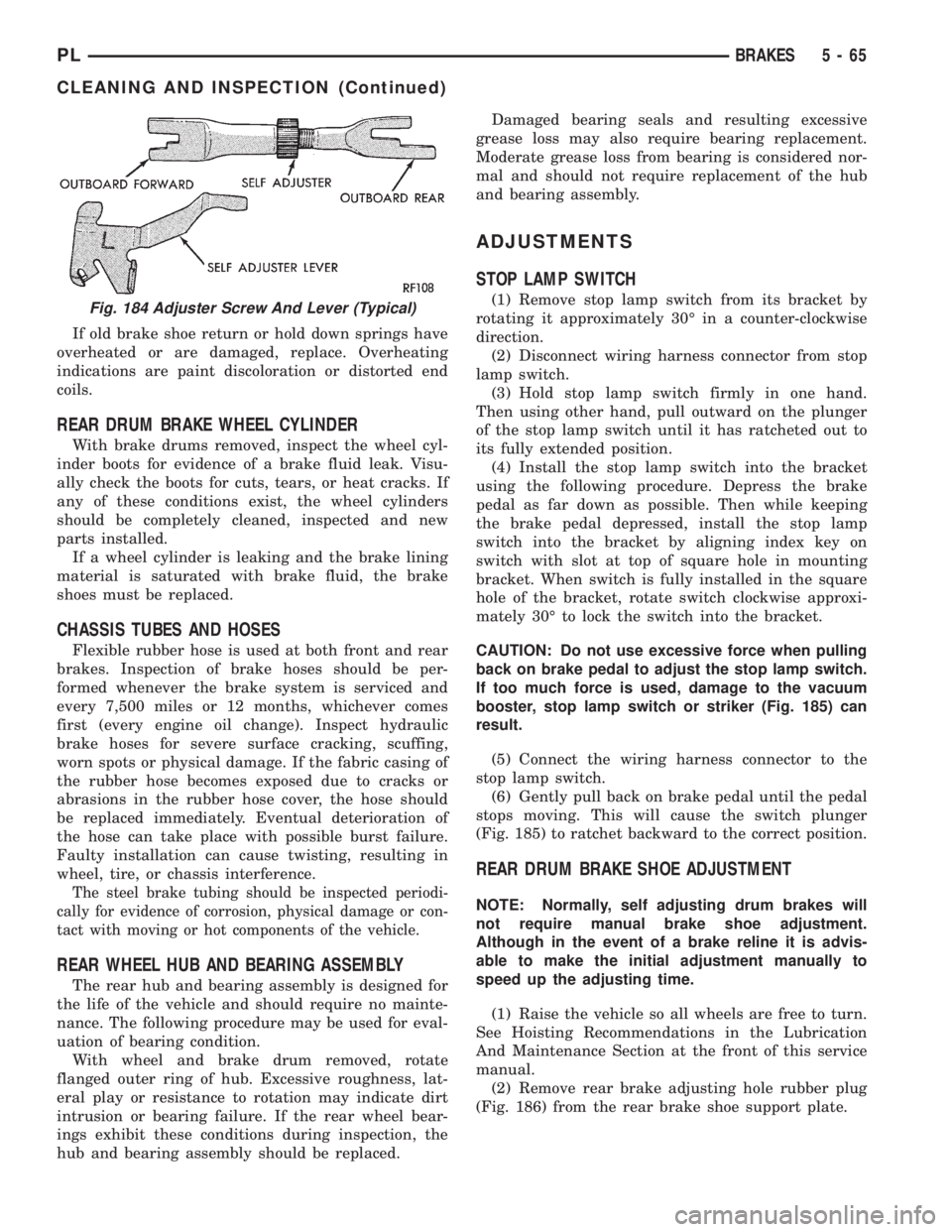
Fig. 184 Adjuster Screw And Lever (Typical)
PLBRAKES 5 - 65
CLEANING AND INSPECTION (Continued)
Page 150 of 1200
ANTILOCK BRAKE SYSTEM±TEVES MARK 20
INDEX
page page
DESCRIPTION AND OPERATION
ABS BRAKE SYSTEM COMPONENTS........ 71
ABS BRAKES OPERATION AND VEHICLE
PERFORMANCE....................... 69
ABS COMPONENT ABBREVIATION LIST...... 69
ABS FLUID ACCUMULATORS.............. 72
ABS FUSES............................ 73
ABS MASTER CYLINDER AND POWER BRAKE
BOOSTER............................ 71
ABS RELAYS........................... 73
ABS WARNING LAMP (YELLOW)............ 75
ANTILOCK BRAKES OPERATION
DESCRIPTION........................ 69
CONTROLLER ANTILOCK BRAKES (CAB)..... 74
HCU PUMP/MOTOR..................... 72
HYDRAULIC CIRCUITS AND VALVE
OPERATION.......................... 75
INLET VALVES AND SOLENOIDS............ 72
INTEGRATED CONTROL UNIT (ICU)......... 71
OUTLET VALVES AND SOLENOIDS.......... 72
PROPORTIONING VALVE................. 73
WHEEL SPEED SENSORS................. 73
DIAGNOSIS AND TESTING
ABS DIAGNOSTIC TROUBLE CODES........ 78
ABS DIAGNOSTICS MANUAL.............. 76
ABS GENERAL DIAGNOSTICS INFORMATION . 75
ABS SERVICE PRECAUTIONS.............. 76
ABS SYSTEM SELF DIAGNOSTICS.......... 77ABS WIRING DIAGRAM INFORMATION....... 76
BRAKE FLUID CONTAMINATION............ 80
DRB DIAGNOSTIC CONNECTOR............ 77
DRB DIAGNOSTIC SCAN TOOL USAGE...... 77
INTERMITTENT DIAGNOSTIC TROUBLE
CODES.............................. 78
PROPORTIONING VALVE................. 79
TEST DRIVING ABS COMPLAINT VEHICLE.... 80
TONEWHEEL INSPECTION................ 79
SERVICE PROCEDURES
BLEEDING TEVES MARK 20 HYDRAULIC
SYSTEM............................. 81
BRAKE FLUID LEVEL INSPECTION.......... 80
REMOVAL AND INSTALLATION
ABS GENERAL SERVICE PRECAUTIONS..... 81
ABS HYDRAULIC CONTROL UNIT........... 82
CONTROLLER ANTILOCK BRAKES (CAB)..... 86
FRONT WHEEL SPEED SENSOR........... 87
MASTER CYLINDER AND POWER BRAKE
BOOSTER............................ 86
PROPORTIONING VALVES................ 86
REAR WHEEL SPEED SENSOR............ 88
SPECIFICATIONS
BRAKE FASTENER TORQUE SPECIFICATIONS . 89
SPEED SENSOR TONE WHEEL RUNOUT..... 89
WHEEL SPEED SENSOR TO TONE WHEEL
CLEARANCE.......................... 89
DESCRIPTION AND OPERATION
ANTILOCK BRAKES OPERATION DESCRIPTION
The purpose of an Antilock Brake System (ABS) is
to prevent wheel lock-up under braking conditions on
virtually any type of road surface. Antilock Braking
is desirable because a vehicle which is stopped with-
out locking the wheels will retain directional stability
and some steering capability. This allows the driver
to retain greater control of the vehicle during brak-
ing.
This section of the service manual covers the
description and on car service for the ITT Teves
Mark 20 ABS Brake System. If other service is
required on the non ABS related components of the
brake system, refer to the appropriate section in this
group of the service manual for the specific service
procedure required.
ABS COMPONENT ABBREVIATION LIST
In this section of the service manual, several
abbreviations are used for the components of the
Teves Mark 20 ABS Brake System. They are listed
below for your reference.
²CAB±Controller Antilock Brake
²ICU±Integrated Control Unit
²HCU±Hydraulic Control Unit
²ABS±Antilock Brake System
²PSI±Pounds Per Square Inch (pressure)
²WSS±Wheel Speed Sensor
²FWD±Front Wheel Drive
²DTC±Diagnostic Trouble Code
ABS BRAKES OPERATION AND VEHICLE
PERFORMANCE
This ABS System represents the current state-of-
the-art in vehicle braking systems and offers the
driver increased safety and control during braking.
PLBRAKES 5 - 69
Page 155 of 1200
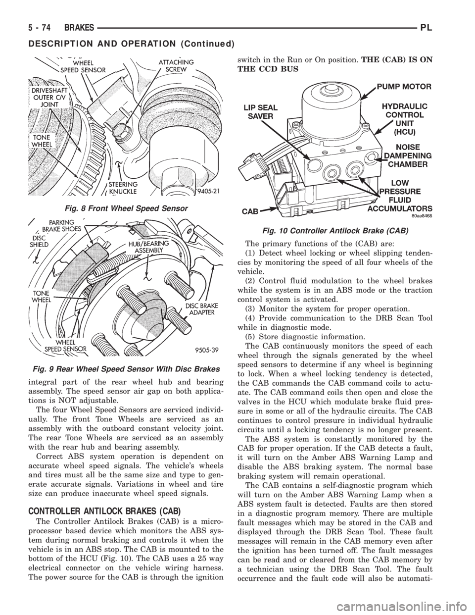
integral part of the rear wheel hub and bearing
assembly. The speed sensor air gap on both applica-
tions is NOT adjustable.
The four Wheel Speed Sensors are serviced individ-
ually. The front Tone Wheels are serviced as an
assembly with the outboard constant velocity joint.
The rear Tone Wheels are serviced as an assembly
with the rear hub and bearing assembly.
Correct ABS system operation is dependent on
accurate wheel speed signals. The vehicle's wheels
and tires must all be the same size and type to gen-
erate accurate signals. Variations in wheel and tire
size can produce inaccurate wheel speed signals.
CONTROLLER ANTILOCK BRAKES (CAB)
The Controller Antilock Brakes (CAB) is a micro-
processor based device which monitors the ABS sys-
tem during normal braking and controls it when the
vehicle is in an ABS stop. The CAB is mounted to the
bottom of the HCU (Fig. 10). The CAB uses a 25 way
electrical connector on the vehicle wiring harness.
The power source for the CAB is through the ignitionswitch in the Run or On position.THE (CAB) IS ON
THE CCD BUS
The primary functions of the (CAB) are:
(1) Detect wheel locking or wheel slipping tenden-
cies by monitoring the speed of all four wheels of the
vehicle.
(2) Control fluid modulation to the wheel brakes
while the system is in an ABS mode or the traction
control system is activated.
(3) Monitor the system for proper operation.
(4) Provide communication to the DRB Scan Tool
while in diagnostic mode.
(5) Store diagnostic information.
The CAB continuously monitors the speed of each
wheel through the signals generated by the wheel
speed sensors to determine if any wheel is beginning
to lock. When a wheel locking tendency is detected,
the CAB commands the CAB command coils to actu-
ate. The CAB command coils then open and close the
valves in the HCU which modulate brake fluid pres-
sure in some or all of the hydraulic circuits. The CAB
continues to control pressure in individual hydraulic
circuits until a locking tendency is no longer present.
The ABS system is constantly monitored by the
CAB for proper operation. If the CAB detects a fault,
it will turn on the Amber ABS Warning Lamp and
disable the ABS braking system. The normal base
braking system will remain operational.
The CAB contains a self-diagnostic program which
will turn on the Amber ABS Warning Lamp when a
ABS system fault is detected. Faults are then stored
in a diagnostic program memory. There are multiple
fault messages which may be stored in the CAB and
displayed through the DRB Scan Tool. These fault
messages will remain in the CAB memory even after
the ignition has been turned off. The fault messages
can be read and or cleared from the CAB memory by
a technician using the DRB Scan Tool. The fault
occurrence and the fault code will also be automati-
Fig. 8 Front Wheel Speed Sensor
Fig. 9 Rear Wheel Speed Sensor With Disc Brakes
Fig. 10 Controller Antilock Brake (CAB)
5 - 74 BRAKESPL
DESCRIPTION AND OPERATION (Continued)
Page 157 of 1200
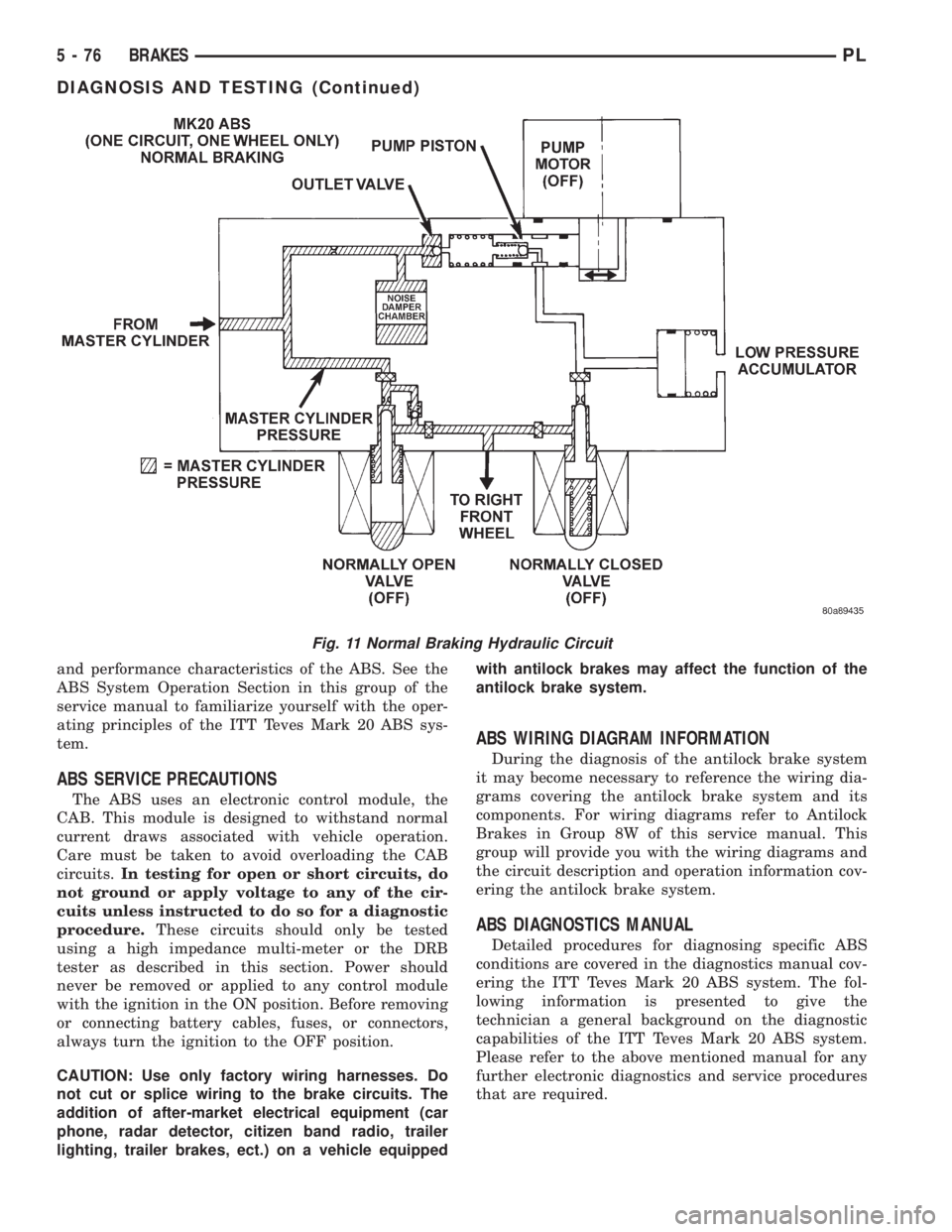
and performance characteristics of the ABS. See the
ABS System Operation Section in this group of the
service manual to familiarize yourself with the oper-
ating principles of the ITT Teves Mark 20 ABS sys-
tem.
ABS SERVICE PRECAUTIONS
The ABS uses an electronic control module, the
CAB. This module is designed to withstand normal
current draws associated with vehicle operation.
Care must be taken to avoid overloading the CAB
circuits.In testing for open or short circuits, do
not ground or apply voltage to any of the cir-
cuits unless instructed to do so for a diagnostic
procedure.These circuits should only be tested
using a high impedance multi-meter or the DRB
tester as described in this section. Power should
never be removed or applied to any control module
with the ignition in the ON position. Before removing
or connecting battery cables, fuses, or connectors,
always turn the ignition to the OFF position.
CAUTION: Use only factory wiring harnesses. Do
not cut or splice wiring to the brake circuits. The
addition of after-market electrical equipment (car
phone, radar detector, citizen band radio, trailer
lighting, trailer brakes, ect.) on a vehicle equippedwith antilock brakes may affect the function of the
antilock brake system.
ABS WIRING DIAGRAM INFORMATION
During the diagnosis of the antilock brake system
it may become necessary to reference the wiring dia-
grams covering the antilock brake system and its
components. For wiring diagrams refer to Antilock
Brakes in Group 8W of this service manual. This
group will provide you with the wiring diagrams and
the circuit description and operation information cov-
ering the antilock brake system.
ABS DIAGNOSTICS MANUAL
Detailed procedures for diagnosing specific ABS
conditions are covered in the diagnostics manual cov-
ering the ITT Teves Mark 20 ABS system. The fol-
lowing information is presented to give the
technician a general background on the diagnostic
capabilities of the ITT Teves Mark 20 ABS system.
Please refer to the above mentioned manual for any
further electronic diagnostics and service procedures
that are required.
Fig. 11 Normal Braking Hydraulic Circuit
5 - 76 BRAKESPL
DIAGNOSIS AND TESTING (Continued)