seats DODGE NEON 1999 Service Repair Manual
[x] Cancel search | Manufacturer: DODGE, Model Year: 1999, Model line: NEON, Model: DODGE NEON 1999Pages: 1200, PDF Size: 35.29 MB
Page 43 of 1200
²Binding strut assembly pivot bearing. If pivot
bearing is replaced it is to be installed with the white
side of bearing facing up (Fig. 74).
²Inspect dust shield for rips and/or deterioration.
²Inspect jounce bumper for cracks and signs of
deterioration.
(11) Replace any components of the strut assembly
found to be worn or defective during the inspection,
before assembling the strut.
ASSEMBLE
(1) Clamp the strut assembly in a vise, with the
strut in a vertical position.When clamping the
strut assembly in the vise, do not clamp strut
using the body of the strut only by strut clevis
bracket (Fig. 67).
(2) Install the compressed coil spring onto the
strut. Coil spring is to be installed with smaller coil
down, so spring correctly seats on strut assembly
(Fig. 73).
(3) Install jounce bumper on the strut shaft (Fig.
72).
(4) Install dust shield, pivot bearing and upper
spring seat as an assembly on the strut (Fig. 71).
(5) Position upper spring seat alignment notch
with clevis bracket on strut assembly.
(6) Install strut mount on strut assembly (Fig. 70)
and the strut mount retaining nut on the shaft of the
strut assembly.
WARNING: THE FOLLOWING 2 STEPS MUST BE
COMPLETELY DONE BEFORE SPRING COMPRES-
SOR, SPECIAL TOOL C-4838 IS RELEASED FROM
THE COIL SPRING.
(7) Install Socket, Strut Nut, Special Tool L-4558A
(or L-4558) on the strut shaft retaining nut (Fig. 69).
Then install a 10 mm socket through the center of
the socket and on the hex of the strut shaft (Fig. 69).
While holding strut shaft from turning, torque strut
shaft retaining nut to 75 N´m (55 ft. lbs.).
(8) Equally loosen both Spring Compressors, Spe-
cial Tool C-4838 until top coil of spring is fully seated
against upper spring seat and strut mount. Then
relieve all tension from spring compressors and
remove spring compressors from strut assembly
spring.
BALL JOINT
DISASSEMBLE
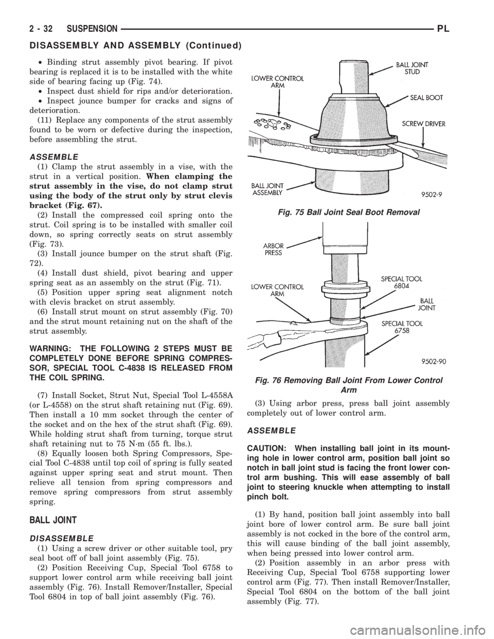
(1) Using a screw driver or other suitable tool, pry
seal boot off of ball joint assembly (Fig. 75).
(2) Position Receiving Cup, Special Tool 6758 to
support lower control arm while receiving ball joint
assembly (Fig. 76). Install Remover/Installer, Special
Tool 6804 in top of ball joint assembly (Fig. 76).(3) Using arbor press, press ball joint assembly
completely out of lower control arm.
ASSEMBLE
CAUTION: When installing ball joint in its mount-
ing hole in lower control arm, position ball joint so
notch in ball joint stud is facing the front lower con-
trol arm bushing. This will ease assembly of ball
joint to steering knuckle when attempting to install
pinch bolt.
(1) By hand, position ball joint assembly into ball
joint bore of lower control arm. Be sure ball joint
assembly is not cocked in the bore of the control arm,
this will cause binding of the ball joint assembly,
when being pressed into lower control arm.
(2) Position assembly in an arbor press with
Receiving Cup, Special Tool 6758 supporting lower
control arm (Fig. 77). Then install Remover/Installer,
Special Tool 6804 on the bottom of the ball joint
assembly (Fig. 77).
Fig. 75 Ball Joint Seal Boot Removal
Fig. 76 Removing Ball Joint From Lower Control
Arm
2 - 32 SUSPENSIONPL
DISASSEMBLY AND ASSEMBLY (Continued)
Page 87 of 1200
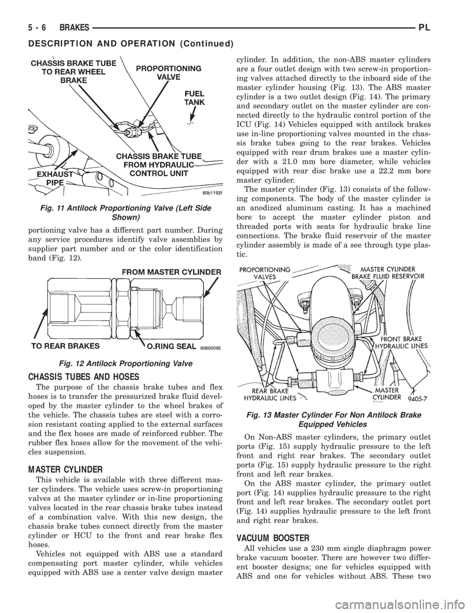
portioning valve has a different part number. During
any service procedures identify valve assemblies by
supplier part number and or the color identification
band (Fig. 12).
CHASSIS TUBES AND HOSES
The purpose of the chassis brake tubes and flex
hoses is to transfer the pressurized brake fluid devel-
oped by the master cylinder to the wheel brakes of
the vehicle. The chassis tubes are steel with a corro-
sion resistant coating applied to the external surfaces
and the flex hoses are made of reinforced rubber. The
rubber flex hoses allow for the movement of the vehi-
cles suspension.
MASTER CYLINDER
This vehicle is available with three different mas-
ter cylinders. The vehicle uses screw-in proportioning
valves at the master cylinder or in-line proportioning
valves located in the rear chassis brake tubes instead
of a combination valve. With this new design, the
chassis brake tubes connect directly from the master
cylinder or HCU to the front and rear brake flex
hoses.
Vehicles not equipped with ABS use a standard
compensating port master cylinder, while vehicles
equipped with ABS use a center valve design mastercylinder. In addition, the non-ABS master cylinders
are a four outlet design with two screw-in proportion-
ing valves attached directly to the inboard side of the
master cylinder housing (Fig. 13). The ABS master
cylinder is a two outlet design (Fig. 14). The primary
and secondary outlet on the master cylinder are con-
nected directly to the hydraulic control portion of the
ICU (Fig. 14) Vehicles equipped with antilock brakes
use in-line proportioning valves mounted in the chas-
sis brake tubes going to the rear brakes. Vehicles
equipped with rear drum brakes use a master cylin-
der with a 21.0 mm bore diameter, while vehicles
equipped with rear disc brake use a 22.2 mm bore
master cylinder.
The master cylinder (Fig. 13) consists of the follow-
ing components. The body of the master cylinder is
an anodized aluminum casting. It has a machined
bore to accept the master cylinder piston and
threaded ports with seats for hydraulic brake line
connections. The brake fluid reservoir of the master
cylinder assembly is made of a see through type plas-
tic.
On Non-ABS master cylinders, the primary outlet
ports (Fig. 15) supply hydraulic pressure to the left
front and right rear brakes. The secondary outlet
ports (Fig. 15) supply hydraulic pressure to the right
front and left rear brakes.
On the ABS master cylinder, the primary outlet
port (Fig. 14) supplies hydraulic pressure to the right
front and left rear brakes. The secondary outlet port
(Fig. 14) supplies hydraulic pressure to the left front
and right rear brakes.
VACUUM BOOSTER
All vehicles use a 230 mm single diaphragm power
brake vacuum booster. There are however two differ-
ent booster designs; one for vehicles equipped with
ABS and one for vehicles without ABS. These two
Fig. 11 Antilock Proportioning Valve (Left Side
Shown)
Fig. 12 Antilock Proportioning Valve
Fig. 13 Master Cylinder For Non Antilock Brake
Equipped Vehicles
5 - 6 BRAKESPL
DESCRIPTION AND OPERATION (Continued)
Page 724 of 1200
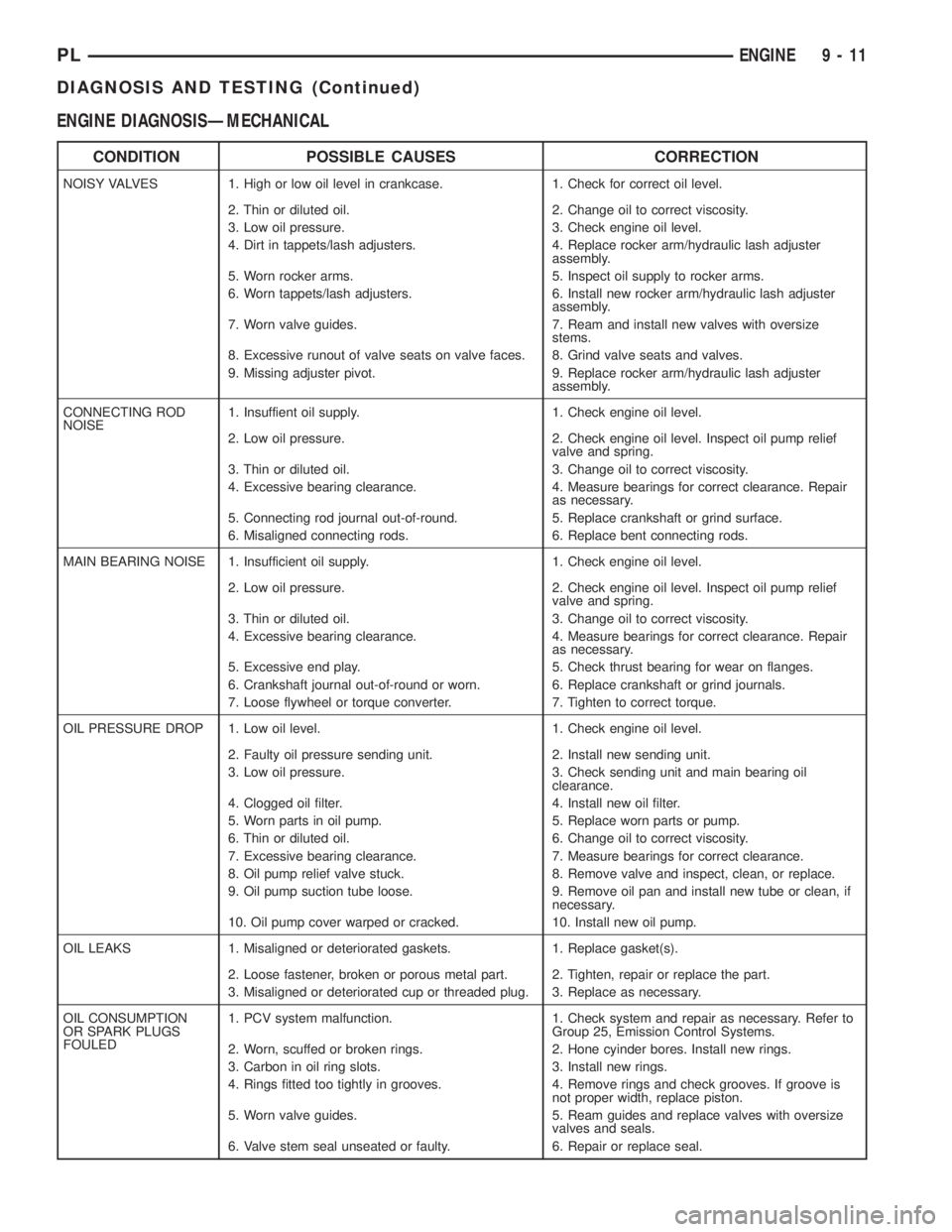
ENGINE DIAGNOSISÐMECHANICAL
CONDITION POSSIBLE CAUSES CORRECTION
NOISY VALVES 1. High or low oil level in crankcase. 1. Check for correct oil level.
2. Thin or diluted oil. 2. Change oil to correct viscosity.
3. Low oil pressure. 3. Check engine oil level.
4. Dirt in tappets/lash adjusters. 4. Replace rocker arm/hydraulic lash adjuster
assembly.
5. Worn rocker arms. 5. Inspect oil supply to rocker arms.
6. Worn tappets/lash adjusters. 6. Install new rocker arm/hydraulic lash adjuster
assembly.
7. Worn valve guides. 7. Ream and install new valves with oversize
stems.
8. Excessive runout of valve seats on valve faces. 8. Grind valve seats and valves.
9. Missing adjuster pivot. 9. Replace rocker arm/hydraulic lash adjuster
assembly.
CONNECTING ROD
NOISE1. Insuffient oil supply. 1. Check engine oil level.
2. Low oil pressure. 2. Check engine oil level. Inspect oil pump relief
valve and spring.
3. Thin or diluted oil. 3. Change oil to correct viscosity.
4. Excessive bearing clearance. 4. Measure bearings for correct clearance. Repair
as necessary.
5. Connecting rod journal out-of-round. 5. Replace crankshaft or grind surface.
6. Misaligned connecting rods. 6. Replace bent connecting rods.
MAIN BEARING NOISE 1. Insufficient oil supply. 1. Check engine oil level.
2. Low oil pressure. 2. Check engine oil level. Inspect oil pump relief
valve and spring.
3. Thin or diluted oil. 3. Change oil to correct viscosity.
4. Excessive bearing clearance. 4. Measure bearings for correct clearance. Repair
as necessary.
5. Excessive end play. 5. Check thrust bearing for wear on flanges.
6. Crankshaft journal out-of-round or worn. 6. Replace crankshaft or grind journals.
7. Loose flywheel or torque converter. 7. Tighten to correct torque.
OIL PRESSURE DROP 1. Low oil level. 1. Check engine oil level.
2. Faulty oil pressure sending unit. 2. Install new sending unit.
3. Low oil pressure. 3. Check sending unit and main bearing oil
clearance.
4. Clogged oil filter. 4. Install new oil filter.
5. Worn parts in oil pump. 5. Replace worn parts or pump.
6. Thin or diluted oil. 6. Change oil to correct viscosity.
7. Excessive bearing clearance. 7. Measure bearings for correct clearance.
8. Oil pump relief valve stuck. 8. Remove valve and inspect, clean, or replace.
9. Oil pump suction tube loose. 9. Remove oil pan and install new tube or clean, if
necessary.
10. Oil pump cover warped or cracked. 10. Install new oil pump.
OIL LEAKS 1. Misaligned or deteriorated gaskets. 1. Replace gasket(s).
2. Loose fastener, broken or porous metal part. 2. Tighten, repair or replace the part.
3. Misaligned or deteriorated cup or threaded plug. 3. Replace as necessary.
OIL CONSUMPTION
OR SPARK PLUGS
FOULED1. PCV system malfunction. 1. Check system and repair as necessary. Refer to
Group 25, Emission Control Systems.
2. Worn, scuffed or broken rings. 2. Hone cyinder bores. Install new rings.
3. Carbon in oil ring slots. 3. Install new rings.
4. Rings fitted too tightly in grooves. 4. Remove rings and check grooves. If groove is
not proper width, replace piston.
5. Worn valve guides. 5. Ream guides and replace valves with oversize
valves and seals.
6. Valve stem seal unseated or faulty. 6. Repair or replace seal.
PLENGINE 9 - 11
DIAGNOSIS AND TESTING (Continued)
Page 727 of 1200
MAIN/ROD BEARINGS
A diagonal hole in each bulkhead feeds oil to each
main bearing. Drilled passages within the crankshaft
route oil from main bearing journals to connecting
rod journals.
CAMSHAFT/HYDRAULIC LASH ADJUSTERS
A vertical hole at the number five bulkhead routes
pressurized oil through a restrictor up into the cylin-
der head. The rocker shafts route oil to the rocker
arms/hydraulic lash adjuster assemblies.
SPLASH LUBRICATION
Oil returning to the pan from pressurized compo-
nents supplies lubrication to the valve stems. Cylin-
der bores and wrist pins are splash lubricated from
directed slots on the connecting rod thrust collars.
ENGINE COMPONENTS
CYLINDER BLOCK AND BEDPLATE ASSEM-
B LY:A partial open deck is used for cooling and
weight reduction with water pump molded into the
block. Nominal wall thickness is 4 mm. The bedplate
incorporates main bearing caps. Rear seal retainer is
integral with the block.
CRANKSHAFT:A nodular cast iron crankshaft is
used. The engine has 5 main bearings, with number
3 flanged to control thrust. The 52 mm diameter
main and 48 mm diameter crank pin journals (all)
have undercut fillet radiuses that are deep rolled for
added strength. To optimize bearing loading 8 coun-
terweights are used. Hydrodynamic seals provide end
sealing, where the crankshaft exits the block.
Anaerobic gasket material is used for parting line
sealing. A sintered iron timing belt sprocket is
mounted on the crankshaft nose. This sprocket trans-
mits crankshaft movement, via timing belt to the
camshaft sprocket providing timed valve actuation.
PISTONS:The SOHC EngineDOES NOThave
provision for a free wheeling valve train. Non free
wheeling valve train means, in the event of a broken
timing belt Pistons will contact the Valves. All
engines use pressed-in piston pins to attach forged
powdered metal connecting rods. The connecting rods
are a cracked cap design and are not repairable. Hex
head cap screw are used to provide alignment and
durability in the assembly. Pistons And Connecting
rods are serviced as an assembly.
PISTON RINGS:The piston rings include a
molybdenum faced top ring for reliable compression
sealing and a taper faced intermediate ring for addi-
tional cylinder pressure control. Oil Control Ring
Package consist of 2 steel rails and a expander
spacer.
CYLINDER HEADÐSOHC:It features a Single
Over Head Camshaft, four-valves per cylinder cross
flow design. The valves are arranged in two inlinebanks, with the two intake per cylinder facing
toward the radiator. The exhaust valves facing
toward the dash panel. Rocker arm shafts mount
directly to the cylinder head. It incorporates powder
metal valve guides and seats. The hollow rocker arm
shafts supplies oil to the hydraulic lash adjusters,
camshaft and valve mechanisms.
CAMSHAFTÐSOHC:The nodular iron camshaft
has five bearing journals and 3 cam lobes per cylin-
der. Provision for cam position sensor on the cam at
the rear of cylinder head which also acts as thrust
plate. A hydrodynamic oil seal is used for oil control
at the front of the camshaft.
VALVESÐSOHC:Four valves per cylinder are
actuated by roller rocker arms/hydraulic lash adjust-
ers assemblies which pivot on rocker arm shafts. All
valves have 6 mm diameter chrome plated valve
stems. The valve train has 33 mm (1.299 inch) diam-
eter intake valves and 28 mm (1.10 inch) diameter
exhaust valves. Viton rubber valve stem seals are
integral with spring seats. Valve springs, spring
retainers, and locks are conventional design.
INTAKE MANIFOLD:The intake manifold is a
molded plastic composition, attached to the cylinder
head with ten fasteners. This long branch design
enhances low and mid-range torque.
EXHAUST MANIFOLD:The exhaust manifold is
made of nodular cast iron for strength and high tem-
peratures. Exhaust gasses exit through a machined,
articulated joint connection to the exhaust pipe.
DIAGNOSIS AND TESTING
CHECKING ENGINE OIL PRESSURE
(1) Remove oil pressure switch and install gauge
assembly C-3292 with adaptor.
(2) Run engine until thermostat opens.
CAUTION: If oil pressure is 0 at idle, Do Not per-
form the 3000 RPM test in the next step.
(3) Oil Pressure:Curb Idle25 kPa (4 psi) mini-
mum3000 RPM170-550 kPa (25-80 psi).
(4) If oil pressure is 0 at idle. Shut off engine,
check for pressure relief valve stuck open, a clogged
oil pick-up screen or a damaged oil pick-up tube
O-ring.
SERVICE PROCEDURES
CYLINDER BORE AND PISTON SIZING
The cylinder walls should be checked for out-of-
round and taper with Tool C-119 (Fig. 3). The cylin-
der bore out-of-round is 0.050 mm (.002 inch)
maximum and cylinder bore taper is 0.051 mm (0.002
9 - 14 2.0L SOHC ENGINEPL
DESCRIPTION AND OPERATION (Continued)
Page 761 of 1200
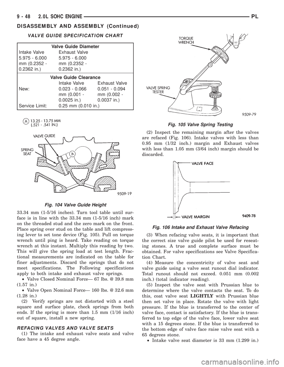
33.34 mm (1-5/16 inches). Turn tool table until sur-
face is in line with the 33.34 mm (1-5/16 inch) mark
on the threaded stud and the zero mark on the front.
Place spring over stud on the table and lift compress-
ing lever to set tone device (Fig. 105). Pull on torque
wrench until ping is heard. Take reading on torque
wrench at this instant. Multiply this reading by two.
This will give the spring load at test length. Frac-
tional measurements are indicated on the table for
finer adjustments. Discard the springs that do not
meet specifications. The Following specifications
apply to both intake and exhaust valve springs.
²Valve Closed Nominal ForceÐ 67 lbs. @ 39.8 mm
(1.57 in.)
²Valve Open Nominal ForceÐ 160 lbs. @ 32.6 mm
(1.28 in.)
(2) Verify springs are not distorted with a steel
square and surface plate, check springs from both
ends. If the spring is more than 1.5 mm (1/16 inch)
out of square, install a new spring.
REFACING VALVES AND VALVE SEATS
(1) The intake and exhaust valve seats and valve
face have a 45 degree angle.(2) Inspect the remaining margin after the valves
are refaced (Fig. 106). Intake valves with less than
0.95 mm (1/32 inch.) margin and Exhaust valves
with less than 1.05 mm (3/64 inch) margin should be
discarded.
(3) When refacing valve seats, it is important that
the correct size valve guide pilot be used for reseat-
ing stones. A true and complete surface must be
obtained. For valve specifications see Valve Specifica-
tion Chart.
(4) Measure the concentricity of valve seat and
valve guide using a valve seat runout dial indicator.
Total runout should not exceed. 0.051 mm (0.002
inch.) (total indicator reading).
(5) Inspect the valve seat with Prussian blue to
determine where the valve contacts the seat. To do
this, coat valve seatLIGHTLYwith Prussian blue
then set valve in place. Rotate the valve with light
pressure. If the blue is transferred to the center of
valve face, contact is satisfactory. If the blue is trans-
ferred to top edge of the valve face, lower valve seat
with a 15 degrees stone. If the blue is transferred to
the bottom edge of valve face raise valve seat with a
65 degrees stone.
²Intake valve seat diameter is 33 mm (1.299 in.)
VALVE GUIDE SPECIFICATION CHART
Valve Guide Diameter
Intake Valve Exhaust Valve
5.975 - 6.000
mm (0.2352 -
0.2362 in.)5.975 - 6.000
mm (0.2352 -
0.2362 in.)
Valve Guide Clearance
Intake Valve Exhaust Valve
New: 0.023 - 0.066
mm (0.001 -
0.0025 in.)0.051 - 0.094
mm (0.002 -
0.0037 in.)
Service Limit: 0.25 mm (0.010 in.)
Fig. 104 Valve Guide Height
Fig. 105 Valve Spring Testing
Fig. 106 Intake and Exhaust Valve Refacing
9 - 48 2.0L SOHC ENGINEPL
DISASSEMBLY AND ASSEMBLY (Continued)
Page 762 of 1200
²Exhaust valve seat diameter is 28 mm (1.102
in.)
(6) Valve seats which are worn or burned can be
reworked, provided that correct angle and seat width
are maintained. The intake valve seat must be ser-
viced when the valve seat width is 2.0 mm (0.079 in.)
or greater. The exhaust valve seat must be serviced
when the valve seat width is 2.5 mm (0.098 in.) or
greater. Otherwise the cylinder head must be
replaced.
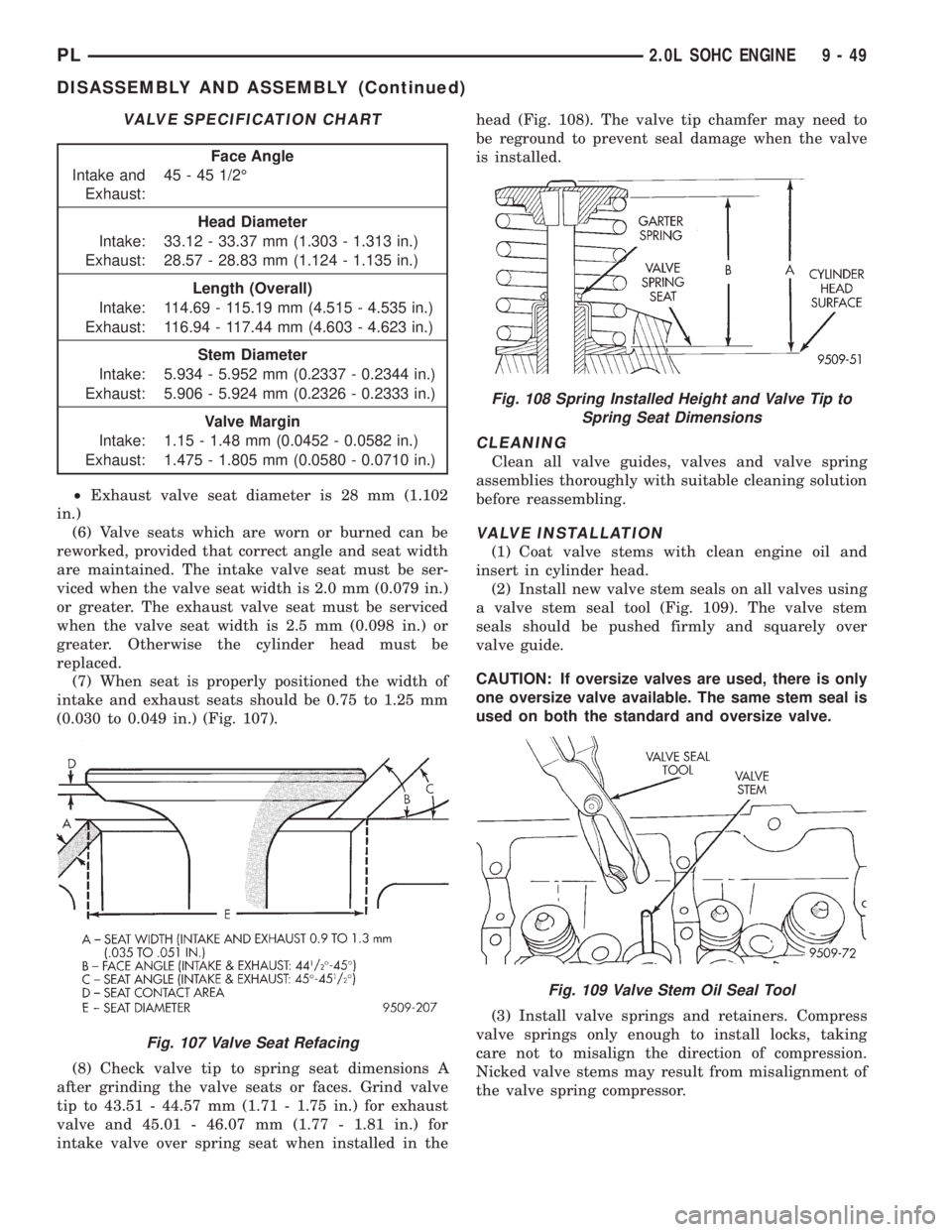
(7) When seat is properly positioned the width of
intake and exhaust seats should be 0.75 to 1.25 mm
(0.030 to 0.049 in.) (Fig. 107).
(8) Check valve tip to spring seat dimensions A
after grinding the valve seats or faces. Grind valve
tip to 43.51 - 44.57 mm (1.71 - 1.75 in.) for exhaust
valve and 45.01 - 46.07 mm (1.77 - 1.81 in.) for
intake valve over spring seat when installed in thehead (Fig. 108). The valve tip chamfer may need to
be reground to prevent seal damage when the valve
is installed.
CLEANING
Clean all valve guides, valves and valve spring
assemblies thoroughly with suitable cleaning solution
before reassembling.
VALVE INSTALLATION
(1) Coat valve stems with clean engine oil and
insert in cylinder head.
(2) Install new valve stem seals on all valves using
a valve stem seal tool (Fig. 109). The valve stem
seals should be pushed firmly and squarely over
valve guide.
CAUTION: If oversize valves are used, there is only
one oversize valve available. The same stem seal is
used on both the standard and oversize valve.
(3) Install valve springs and retainers. Compress
valve springs only enough to install locks, taking
care not to misalign the direction of compression.
Nicked valve stems may result from misalignment of
the valve spring compressor.
VALVE SPECIFICATION CHART
Face Angle
Intake and
Exhaust:45 - 45 1/2É
Head Diameter
Intake: 33.12 - 33.37 mm (1.303 - 1.313 in.)
Exhaust: 28.57 - 28.83 mm (1.124 - 1.135 in.)
Length (Overall)
Intake: 114.69 - 115.19 mm (4.515 - 4.535 in.)
Exhaust: 116.94 - 117.44 mm (4.603 - 4.623 in.)
Stem Diameter
Intake: 5.934 - 5.952 mm (0.2337 - 0.2344 in.)
Exhaust: 5.906 - 5.924 mm (0.2326 - 0.2333 in.)
Valve Margin
Intake: 1.15 - 1.48 mm (0.0452 - 0.0582 in.)
Exhaust: 1.475 - 1.805 mm (0.0580 - 0.0710 in.)
Fig. 107 Valve Seat Refacing
Fig. 108 Spring Installed Height and Valve Tip to
Spring Seat Dimensions
Fig. 109 Valve Stem Oil Seal Tool
PL2.0L SOHC ENGINE 9 - 49
DISASSEMBLY AND ASSEMBLY (Continued)
Page 773 of 1200
incorporates main bearing caps. Rear seal retainer is
integral with the block.
CRANKSHAFTA nodular cast iron crankshaft is
used. The engine has 5 main bearings, with number
3 flanged to control thrust. The 52 mm diameter
main and 48 mm diameter crank pin journals (all)
have undercut fillet radiuses that are deep rolled for
added strength. To optimize bearing loading 8 coun-
terweights are used. Hydrodynamic seals provide end
sealing, where the crankshaft exits the block.
Anaerobic gasket material is used for parting line
sealing. A sintered iron timing belt sprocket is
mounted on the crankshaft nose. This sprocket pro-
vides motive power; via timing belt to the camshaft
sprocket providing timed valve actuation.
PISTONSThe DOHC EngineDO NOThave pro-
vision for a free wheeling valve train. Non free
wheeling valve train means, in the event of a broken
timing belt Pistons will contact the Valves. All
engines use pressed-in piston pins to attach forged
powdered metal connecting rods. The connecting rods
are a cracked cap design and are not repairable. Hex
head cap screw are used to provide alignment and
durability in the assembly.
PISTON RINGSThe piston rings include a
molybdenum faced top ring for reliable compression
sealing and a taper faced intermediate ring for addi-
tional cylinder pressure control. Oil Control Ring
Package contains of 2 steel rails and a expander
spacer.
CYLINDER HEADFeatures a Dual Over Head
Camshaft (DOHC), 4 valves per cylinder cross flow
design. The valves are arranged in two in-line banks,
with the ports of the bank of two intake valves per
cylinder facing toward the radiator side of engine
and ports of the bank of two exhaust valves per cyl-
inder facing toward the dash panel. Incorporates
powder metal valve guides and seats. Integral oil gal-
leys within the cylinder head supplies oil to the
hydraulic lash adjusters, camshaft and valve mecha-
nisms.
CAMSHAFTSThe nodular iron camshafts have
six bearing journals and 2 cam lobes per cylinder.
Flanges at the rear journals control camshaft end
play. Provision for cam position sensor is located on
the intake camshaft at the rear of cylinder head. A
hydrodynamic oil seal is used for oil control at the
front of the camshaft.
VA LV E SFour valves per cylinder are actuated by
roller cam followers which pivot on stationary
hydraulic lash adjusters. All valves have 6 mm diam-
eter chrome plated valve stems. The valve sizes are
34.8 mm (1.370 inch.) diameter intake valves and
30.5 mm (1.20 inch.) diameter exhaust valves. Viton
rubber valve stem seals are integral with the springseats. Valve springs, spring retainers, and locks are
conventional.
INTAKE MANIFOLDThe intake manifold is a
two piece aluminum casting, attached to the cylinder
head with ten fasteners. This long branch fan design
enhances low and mid-speed torque.
EXHAUST MANIFOLDThe exhaust manifold is
made of nodular cast iron for strength and high tem-
peratures. Exhaust gasses exit through a machined,
articulated joint connection to the exhaust pipe.
COMPONENT REPLACEMENT
If any of the following parts have been changed or
replaced:
²Camshaft
²Camshaft Position Sensor
²Camshaft Position Sensor Target Magnet
²Cylinder Block
²Cylinder Head
²Water Pump
²Powertrain Control Module (PCM)
²Timing Belt and Timing Belt Tensioner
The camshaft and crankshaft timing relearn proce-
dure must be performed. Refer to the component
Removal and Installation procedure outlined in this
Group.
DIAGNOSIS AND TESTING
CHECKING ENGINE OIL PRESSURE
(1) Remove oil pressure switch and install gauge
assembly C-3292 with adaptor.
(2) Run engine until thermostat opens.
CAUTION: If oil pressure is 0 at idle, Do Not per-
form the 3000 RPM test in the next step.
(3) Oil Pressure:Curb Idle25 kPa (4 psi) mini-
mum3000 RPM170-550 kPa (25-80 psi).
(4) If oil pressure is 0 at idle. Shut off engine,
check for pressure relief valve stuck open, a clogged
oil pick-up screen or a damaged oil pick-up tube
O-ring.
SERVICE PROCEDURES
CYLINDER BORE AND PISTON SIZING
The cylinder walls should be checked for out-of-
round and taper with Tool C-119 (Fig. 4). The cylin-
der bore out-of-round is 0.050 mm (.002 inch)
maximum and cylinder bore taper is 0.051 mm (0.002
inch) maximum. If the cylinder walls are badly
scuffed or scored, the cylinder block should be
rebored and honed, and new pistons and rings fitted.
Whatever type of boring equipment is used, boring
and honing operation should be closely coordinated
9 - 60 2.0L DOHC ENGINEPL
DESCRIPTION AND OPERATION (Continued)
Page 805 of 1200
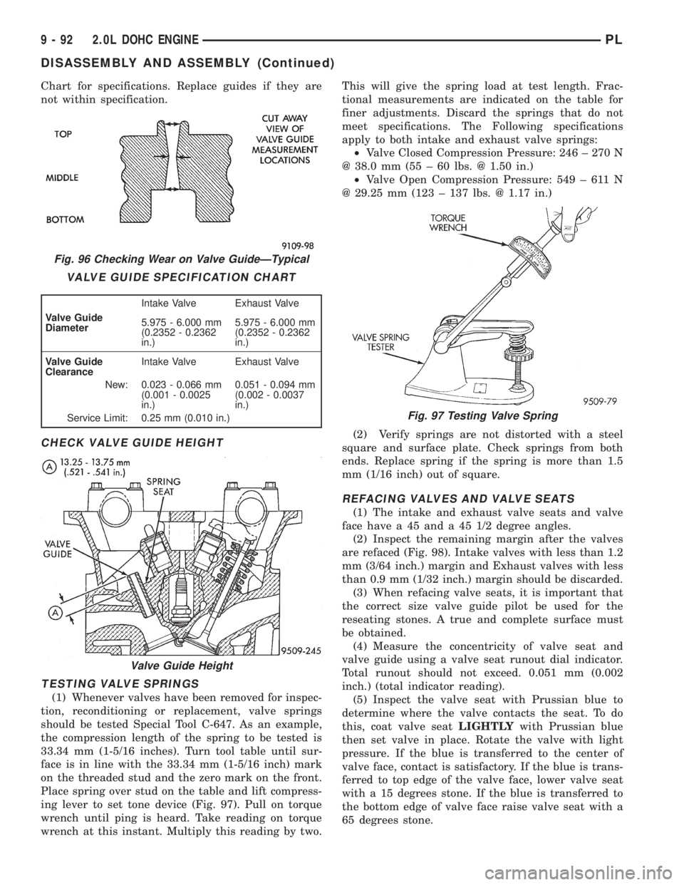
Chart for specifications. Replace guides if they are
not within specification.
CHECK VALVE GUIDE HEIGHT
TESTING VALVE SPRINGS
(1) Whenever valves have been removed for inspec-
tion, reconditioning or replacement, valve springs
should be tested Special Tool C-647. As an example,
the compression length of the spring to be tested is
33.34 mm (1-5/16 inches). Turn tool table until sur-
face is in line with the 33.34 mm (1-5/16 inch) mark
on the threaded stud and the zero mark on the front.
Place spring over stud on the table and lift compress-
ing lever to set tone device (Fig. 97). Pull on torque
wrench until ping is heard. Take reading on torque
wrench at this instant. Multiply this reading by two.This will give the spring load at test length. Frac-
tional measurements are indicated on the table for
finer adjustments. Discard the springs that do not
meet specifications. The Following specifications
apply to both intake and exhaust valve springs:
²Valve Closed Compression Pressure: 246 ± 270 N
@ 38.0 mm (55 ± 60 lbs. @ 1.50 in.)
²Valve Open Compression Pressure: 549 ± 611 N
@ 29.25 mm (123 ± 137 lbs. @ 1.17 in.)
(2) Verify springs are not distorted with a steel
square and surface plate. Check springs from both
ends. Replace spring if the spring is more than 1.5
mm (1/16 inch) out of square.
REFACING VALVES AND VALVE SEATS
(1) The intake and exhaust valve seats and valve
face have a 45 and a 45 1/2 degree angles.
(2) Inspect the remaining margin after the valves
are refaced (Fig. 98). Intake valves with less than 1.2
mm (3/64 inch.) margin and Exhaust valves with less
than 0.9 mm (1/32 inch.) margin should be discarded.
(3) When refacing valve seats, it is important that
the correct size valve guide pilot be used for the
reseating stones. A true and complete surface must
be obtained.
(4) Measure the concentricity of valve seat and
valve guide using a valve seat runout dial indicator.
Total runout should not exceed. 0.051 mm (0.002
inch.) (total indicator reading).
(5) Inspect the valve seat with Prussian blue to
determine where the valve contacts the seat. To do
this, coat valve seatLIGHTLYwith Prussian blue
then set valve in place. Rotate the valve with light
pressure. If the blue is transferred to the center of
valve face, contact is satisfactory. If the blue is trans-
ferred to top edge of the valve face, lower valve seat
with a 15 degrees stone. If the blue is transferred to
the bottom edge of valve face raise valve seat with a
65 degrees stone.
Fig. 96 Checking Wear on Valve GuideÐTypical
VALVE GUIDE SPECIFICATION CHART
Valve Guide
DiameterIntake Valve Exhaust Valve
5.975 - 6.000 mm
(0.2352 - 0.2362
in.)5.975 - 6.000 mm
(0.2352 - 0.2362
in.)
Valve Guide
ClearanceIntake Valve Exhaust Valve
New: 0.023 - 0.066 mm
(0.001 - 0.0025
in.)0.051 - 0.094 mm
(0.002 - 0.0037
in.)
Service Limit: 0.25 mm (0.010 in.)
Valve Guide Height
Fig. 97 Testing Valve Spring
9 - 92 2.0L DOHC ENGINEPL
DISASSEMBLY AND ASSEMBLY (Continued)
Page 806 of 1200
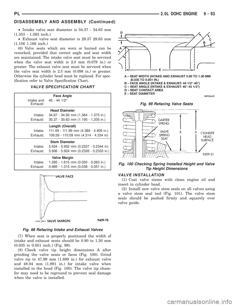
²Intake valve seat diameter is 34.37 - 34.63 mm
(1.353 - 1.363 inch.)
²Exhaust valve seat diameter is 29.37 29.63 mm
(1.156 1.166 inch.)
(6)
Valve seats which are worn or burned can be
reworked, provided that correct angle and seat width
are maintained. The intake valve seat must be serviced
when the valve seat width is 2.0 mm (0.079 in.) or
greater. The exhaust valve seat must be serviced when
the valve seat width is 2.5 mm (0.098 in.) or greater.
Otherwise the cylinder head must be replaced. For spec-
ification refer to Valve Specification Chart.
(7) When seat is properly positioned the width of
intake and exhaust seats should be 0.90 to 1.30 mm
(0.035 to 0.051 inch.) (Fig. 99).
(8) Check valve tip height dimensions A after
grinding the valve seats or faces (Fig. 100). Grind
valve tip to 47.99 mm (1.889 in.) for exhaust valve
and 48.04 mm (1.891 in.) for intake valve when
installed in the head (Fig. 100). The valve tip cham-
fer may need to be reground to prevent seal damage
when the valve is installed.
VALVE INSTALLATION
(1) Coat valve stems with clean engine oil and
insert in cylinder head.
(2) Install new valve stem seals on all valves using
a valve stem seal tool (Fig. 101). The valve stem
seals should be pushed firmly and squarely over
valve guide.
VALVE SPECIFICATION CHART
Face Angle
Intake and
Exhaust:45 - 44 1/2É
Head Diameter
Intake: 34.67 - 34.93 mm (1.364 - 1.375 in.)
Exhaust: 30.37 - 30.63 mm (1.195 - 1.205 in.)
Length (Overall)
Intake: 111.49 - 111.99 mm (4.389 - 4.409 in.)
Exhaust: 109.59 - 110.09 mm (4.314 - 4.334 in)
Stem Diameter
Intake: 5.934 - 5.952 mm (0.2337 - 0.2344 in)
Exhaust: 5.906 - 5.924 mm (0.2326 - 0.2333 in.)
Valve Margin
Intake: 1.285 - 1.615 mm (0.050 - 0.063 in.)
Exhaust: 0.985 - 1.315 mm (0.038 - 0.051 in.)
Fig. 98 Refacing Intake and Exhaust Valves
Fig. 99 Refacing Valve Seats
Fig. 100 Checking Spring Installed Height and Valve
Tip Height Dimensions
PL2.0L DOHC ENGINE 9 - 93
DISASSEMBLY AND ASSEMBLY (Continued)
Page 852 of 1200
The hose clamps have rolled edges to prevent the
clamp from cutting into the hose. Only use clamps
that are original equipment or equivalent. Other
types of clamps may cut into the hoses and cause
high pressure fuel leaks. Tighten hose clamps to 1
N´m (10 in. lbs.) torque.
QUICK-CONNECT FITTINGS
REMOVAL
When disconnecting a quick-connect fitting, the
retainer will remain on the fuel tube nipple.
WARNING: RELEASE FUEL SYSTEM PRESSURE
BEFORE DISCONNECTING A QUICK-CONNECT FIT-
TINGS. REFER TO THE FUEL PRESSURE RELEASE
PROCEDURE.
(1) Disconnect negative cable from battery.
(2) Perform Fuel Pressure Release Procedure.
Refer to the Fuel Pressure Release Procedure in this
section.
(3) Squeeze retainer tabs together and pull fuel
tube/quick-connect fitting assembly off of fuel tube
nipple. The retainer will remain on fuel tube.
INSTALLATION
CAUTION: Never install a quick-connect fitting
without the retainer being either on the fuel tube or
already in the quick-connect fitting. In either case,
ensure the retainer locks securely into the quick-
connect fitting by firmly pulling on fuel tube and fit-
ting to ensure it is secured.
(1) Using a clean lint free cloth, clean the fuel tube
nipple and retainer.
(2) Prior to connecting the fitting to the fuel tube,
coat the fuel tube nipple with clean 30 weight engine
oil.
(3) Push the quick-connect fitting over the fuel
tube until theretainer seats and a click is heard.
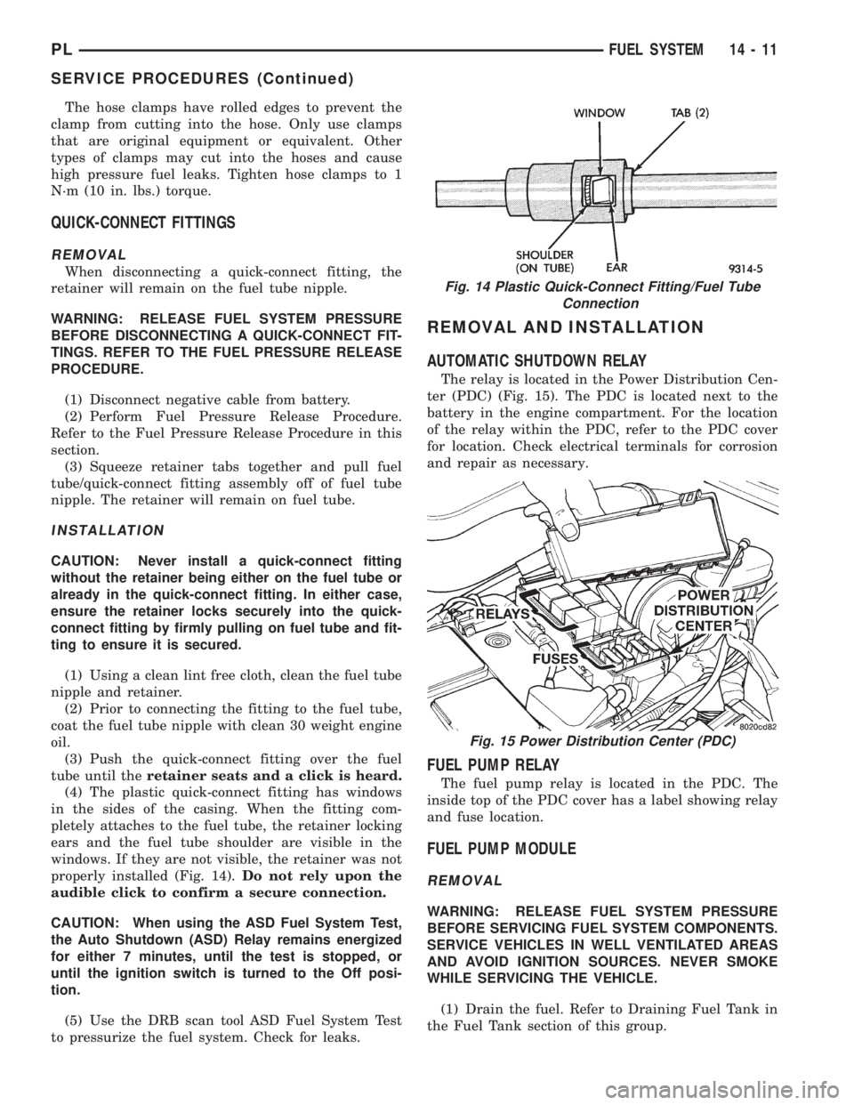
(4) The plastic quick-connect fitting has windows
in the sides of the casing. When the fitting com-
pletely attaches to the fuel tube, the retainer locking
ears and the fuel tube shoulder are visible in the
windows. If they are not visible, the retainer was not
properly installed (Fig. 14).Do not rely upon the
audible click to confirm a secure connection.
CAUTION: When using the ASD Fuel System Test,
the Auto Shutdown (ASD) Relay remains energized
for either 7 minutes, until the test is stopped, or
until the ignition switch is turned to the Off posi-
tion.
(5) Use the DRB scan tool ASD Fuel System Test
to pressurize the fuel system. Check for leaks.
REMOVAL AND INSTALLATION
AUTOMATIC SHUTDOWN RELAY
The relay is located in the Power Distribution Cen-
ter (PDC) (Fig. 15). The PDC is located next to the
battery in the engine compartment. For the location
of the relay within the PDC, refer to the PDC cover
for location. Check electrical terminals for corrosion
and repair as necessary.
FUEL PUMP RELAY
The fuel pump relay is located in the PDC. The
inside top of the PDC cover has a label showing relay
and fuse location.
FUEL PUMP MODULE
REMOVAL
WARNING: RELEASE FUEL SYSTEM PRESSURE
BEFORE SERVICING FUEL SYSTEM COMPONENTS.
SERVICE VEHICLES IN WELL VENTILATED AREAS
AND AVOID IGNITION SOURCES. NEVER SMOKE
WHILE SERVICING THE VEHICLE.
(1) Drain the fuel. Refer to Draining Fuel Tank in
the Fuel Tank section of this group.
Fig. 14 Plastic Quick-Connect Fitting/Fuel Tube
Connection
Fig. 15 Power Distribution Center (PDC)
PLFUEL SYSTEM 14 - 11
SERVICE PROCEDURES (Continued)