brake pads DODGE NEON 1999 Service Repair Manual
[x] Cancel search | Manufacturer: DODGE, Model Year: 1999, Model line: NEON, Model: DODGE NEON 1999Pages: 1200, PDF Size: 35.29 MB
Page 4 of 1200
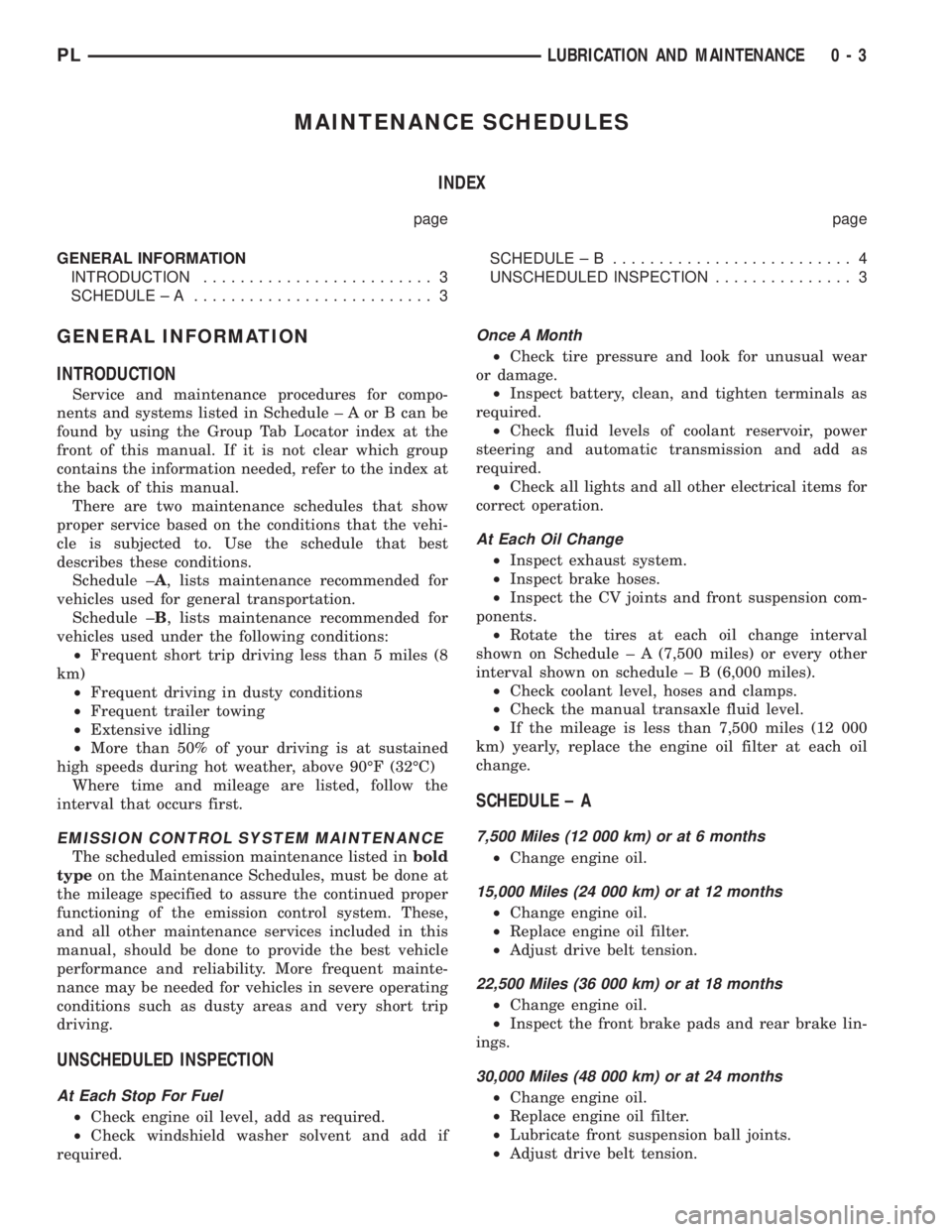
MAINTENANCE SCHEDULES
INDEX
page page
GENERAL INFORMATION
INTRODUCTION......................... 3
SCHEDULE ± A.......................... 3SCHEDULE ± B.......................... 4
UNSCHEDULED INSPECTION............... 3
GENERAL INFORMATION
INTRODUCTION
Service and maintenance procedures for compo-
nents and systems listed in Schedule ± A or B can be
found by using the Group Tab Locator index at the
front of this manual. If it is not clear which group
contains the information needed, refer to the index at
the back of this manual.
There are two maintenance schedules that show
proper service based on the conditions that the vehi-
cle is subjected to. Use the schedule that best
describes these conditions.
Schedule ±A, lists maintenance recommended for
vehicles used for general transportation.
Schedule ±B, lists maintenance recommended for
vehicles used under the following conditions:
²Frequent short trip driving less than 5 miles (8
km)
²Frequent driving in dusty conditions
²Frequent trailer towing
²Extensive idling
²More than 50% of your driving is at sustained
high speeds during hot weather, above 90ÉF (32ÉC)
Where time and mileage are listed, follow the
interval that occurs first.
EMISSION CONTROL SYSTEM MAINTENANCE
The scheduled emission maintenance listed inbold
typeon the Maintenance Schedules, must be done at
the mileage specified to assure the continued proper
functioning of the emission control system. These,
and all other maintenance services included in this
manual, should be done to provide the best vehicle
performance and reliability. More frequent mainte-
nance may be needed for vehicles in severe operating
conditions such as dusty areas and very short trip
driving.
UNSCHEDULED INSPECTION
At Each Stop For Fuel
²Check engine oil level, add as required.
²Check windshield washer solvent and add if
required.
Once A Month
²Check tire pressure and look for unusual wear
or damage.
²Inspect battery, clean, and tighten terminals as
required.
²Check fluid levels of coolant reservoir, power
steering and automatic transmission and add as
required.
²Check all lights and all other electrical items for
correct operation.
At Each Oil Change
²Inspect exhaust system.
²Inspect brake hoses.
²Inspect the CV joints and front suspension com-
ponents.
²Rotate the tires at each oil change interval
shown on Schedule ± A (7,500 miles) or every other
interval shown on schedule ± B (6,000 miles).
²Check coolant level, hoses and clamps.
²Check the manual transaxle fluid level.
²If the mileage is less than 7,500 miles (12 000
km) yearly, replace the engine oil filter at each oil
change.
SCHEDULE ± A
7,500 Miles (12 000 km) or at 6 months
²Change engine oil.
15,000 Miles (24 000 km) or at 12 months
²Change engine oil.
²Replace engine oil filter.
²Adjust drive belt tension.
22,500 Miles (36 000 km) or at 18 months
²Change engine oil.
²Inspect the front brake pads and rear brake lin-
ings.
30,000 Miles (48 000 km) or at 24 months
²Change engine oil.
²Replace engine oil filter.
²Lubricate front suspension ball joints.
²Adjust drive belt tension.
PLLUBRICATION AND MAINTENANCE 0 - 3
Page 5 of 1200
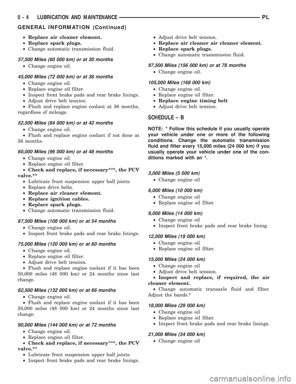
²Replace air cleaner element.
²Replace spark plugs.
²Change automatic transmission fluid.
37,500 Miles (60 000 km) or at 30 months
²Change engine oil.
45,000 Miles (72 000 km) or at 36 months
²Change engine oil.
²Replace engine oil filter.
²Inspect front brake pads and rear brake linings.
²Adjust drive belt tension.
²Flush and replace engine coolant at 36 months,
regardless of mileage.
52,500 Miles (84 000 km) or at 42 months
²Change engine oil.
²Flush and replace engine coolant if not done at
36 months.
60,000 Miles (96 000 km) or at 48 months
²Change engine oil.
²Replace engine oil filter.
²Check and replace, if necessary***, the PCV
valve.**
²Lubricate front suspension upper ball joints.
²Replace drive belts.
²Replace air cleaner element.
²Replace ignition cables.
²Replace spark plugs.
²Change automatic transmission fluid.
67,500 Miles (108 000 km) or at 54 months
²Change engine oil.
²Inspect front brake pads and rear brake linings.
75,000 Miles (120 000 km) or at 60 months
²Change engine oil.
²Replace engine oil filter.
²Adjust drive belt tension.
²Flush and replace engine coolant if it has been
30,000 miles (48 000 km) or 24 months since last
change.
82,500 Miles (132 000 km) or at 66 months
²Change engine oil.
²Flush and replace engine coolant if it has been
30,000 miles (48 000 km) or 24 months since last
change.
90,000 Miles (144 000 km) or at 72 months
²Change engine oil.
²Replace engine oil filter.
²Check and replace, if necessary***, the PCV
valve.**
²Lubricate front suspension upper ball joints.
²Inspect front brake pads and rear brake linings.²Adjust drive belt tension.
²Replace air cleaner air cleaner element.
²Replace spark plugs.
²Change automatic transmission fluid.
97,500 Miles (156 000 km) or at 78 months
²Change engine oil.
105,000 Miles (168 000 km)
²Change engine oil.
²Replace engine oil filter.
²Replace engine timing belt
²Adjust drive belt tension.
SCHEDULE ± B
NOTE: * Follow this schedule if you usually operate
your vehicle under one or more of the following
conditions. Change the automatic transmission
fluid and filter every 15,000 miles (24 000 km) if you
usually operate your vehicle under one of the con-
ditions marked with an *.
3,000 Miles (5 000 km)
²Change engine oil
6,000 Miles (10 000 km)
²Change engine oil
²Replace engine oil filter.
9,000 Miles (14 000 km)
²Change engine oil
²Inspect front brake pads and rear brake lining.
12,000 Miles (19 000 km)
²Change engine oil
²Replace engine oil filter.
15,000 Miles (24 000 km)
²Change engine oil
²Adjust drive belt tension.
²Inspect and replace, if required, the air
cleaner element.
²Change automatic transaxle fluid and filter.
Adjust the bands.*
18,000 Miles (29 000 km)
²Change engine oil
²Replace engine oil filter.
²Inspect front brake pads and rear brake linings.
21,000 Miles (34 000 km)
²Change engine oil
0 - 4 LUBRICATION AND MAINTENANCEPL
GENERAL INFORMATION (Continued)
Page 6 of 1200
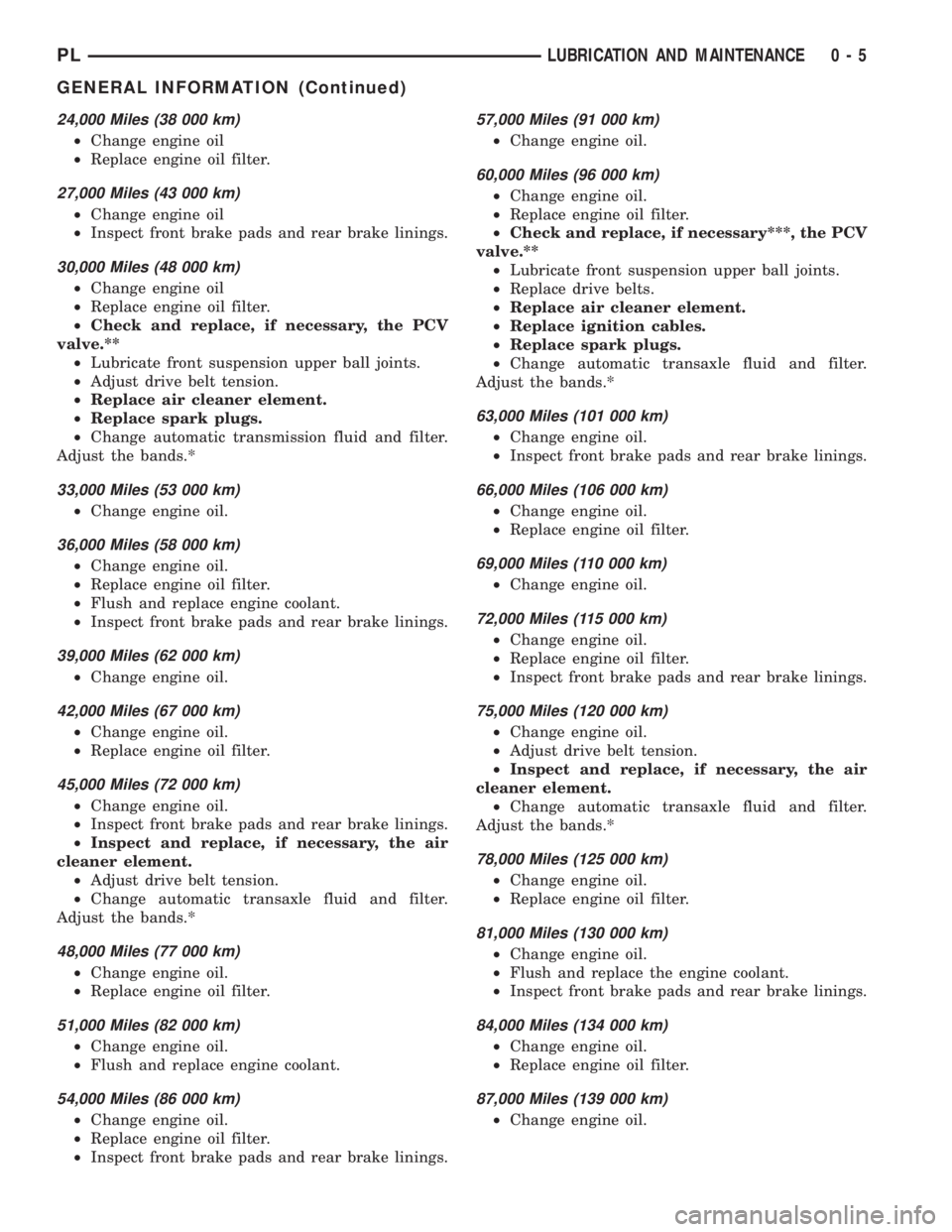
24,000 Miles (38 000 km)
²Change engine oil
²Replace engine oil filter.
27,000 Miles (43 000 km)
²Change engine oil
²Inspect front brake pads and rear brake linings.
30,000 Miles (48 000 km)
²Change engine oil
²Replace engine oil filter.
²Check and replace, if necessary, the PCV
valve.**
²Lubricate front suspension upper ball joints.
²Adjust drive belt tension.
²Replace air cleaner element.
²Replace spark plugs.
²Change automatic transmission fluid and filter.
Adjust the bands.*
33,000 Miles (53 000 km)
²Change engine oil.
36,000 Miles (58 000 km)
²Change engine oil.
²Replace engine oil filter.
²Flush and replace engine coolant.
²Inspect front brake pads and rear brake linings.
39,000 Miles (62 000 km)
²Change engine oil.
42,000 Miles (67 000 km)
²Change engine oil.
²Replace engine oil filter.
45,000 Miles (72 000 km)
²Change engine oil.
²Inspect front brake pads and rear brake linings.
²Inspect and replace, if necessary, the air
cleaner element.
²Adjust drive belt tension.
²Change automatic transaxle fluid and filter.
Adjust the bands.*
48,000 Miles (77 000 km)
²Change engine oil.
²Replace engine oil filter.
51,000 Miles (82 000 km)
²Change engine oil.
²Flush and replace engine coolant.
54,000 Miles (86 000 km)
²Change engine oil.
²Replace engine oil filter.
²Inspect front brake pads and rear brake linings.
57,000 Miles (91 000 km)
²Change engine oil.
60,000 Miles (96 000 km)
²Change engine oil.
²Replace engine oil filter.
²Check and replace, if necessary***, the PCV
valve.**
²Lubricate front suspension upper ball joints.
²Replace drive belts.
²Replace air cleaner element.
²Replace ignition cables.
²Replace spark plugs.
²Change automatic transaxle fluid and filter.
Adjust the bands.*
63,000 Miles (101 000 km)
²Change engine oil.
²Inspect front brake pads and rear brake linings.
66,000 Miles (106 000 km)
²Change engine oil.
²Replace engine oil filter.
69,000 Miles (110 000 km)
²Change engine oil.
72,000 Miles (115 000 km)
²Change engine oil.
²Replace engine oil filter.
²Inspect front brake pads and rear brake linings.
75,000 Miles (120 000 km)
²Change engine oil.
²Adjust drive belt tension.
²Inspect and replace, if necessary, the air
cleaner element.
²Change automatic transaxle fluid and filter.
Adjust the bands.*
78,000 Miles (125 000 km)
²Change engine oil.
²Replace engine oil filter.
81,000 Miles (130 000 km)
²Change engine oil.
²Flush and replace the engine coolant.
²Inspect front brake pads and rear brake linings.
84,000 Miles (134 000 km)
²Change engine oil.
²Replace engine oil filter.
87,000 Miles (139 000 km)
²Change engine oil.
PLLUBRICATION AND MAINTENANCE 0 - 5
GENERAL INFORMATION (Continued)
Page 7 of 1200
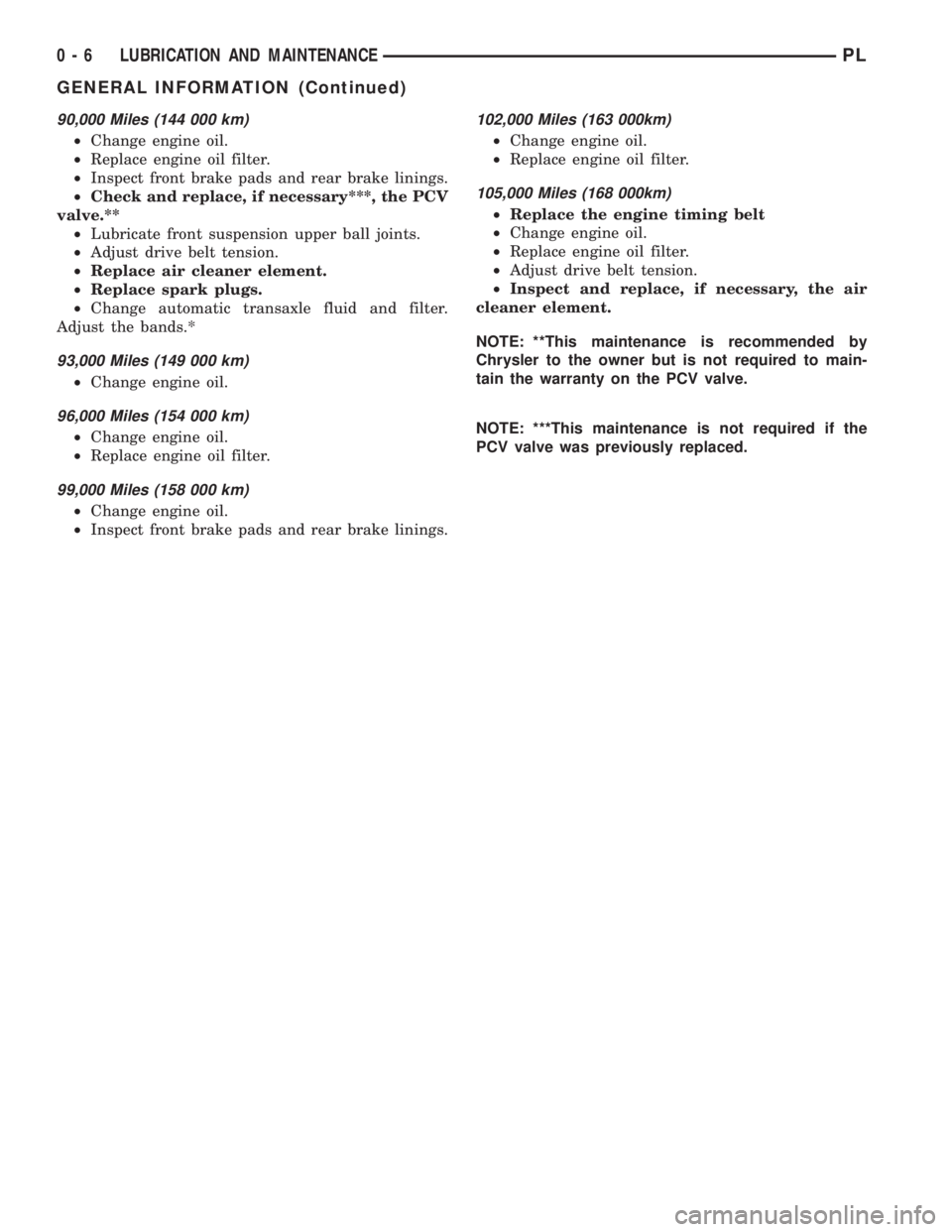
90,000 Miles (144 000 km)
²Change engine oil.
²Replace engine oil filter.
²Inspect front brake pads and rear brake linings.
²Check and replace, if necessary***, the PCV
valve.**
²Lubricate front suspension upper ball joints.
²Adjust drive belt tension.
²Replace air cleaner element.
²Replace spark plugs.
²Change automatic transaxle fluid and filter.
Adjust the bands.*
93,000 Miles (149 000 km)
²Change engine oil.
96,000 Miles (154 000 km)
²Change engine oil.
²Replace engine oil filter.
99,000 Miles (158 000 km)
²Change engine oil.
²Inspect front brake pads and rear brake linings.
102,000 Miles (163 000km)
²Change engine oil.
²Replace engine oil filter.
105,000 Miles (168 000km)
²Replace the engine timing belt
²Change engine oil.
²Replace engine oil filter.
²Adjust drive belt tension.
²Inspect and replace, if necessary, the air
cleaner element.
NOTE: **This maintenance is recommended by
Chrysler to the owner but is not required to main-
tain the warranty on the PCV valve.
NOTE: ***This maintenance is not required if the
PCV valve was previously replaced.
0 - 6 LUBRICATION AND MAINTENANCEPL
GENERAL INFORMATION (Continued)
Page 82 of 1200
BRAKES
CONTENTS
page page
ANTILOCK BRAKE SYSTEM±TEVES MARK 20 . 69
BASE BRAKE SYSTEM..................... 2GENERAL INFORMATION................... 1
GENERAL INFORMATION
INDEX
page
GENERAL INFORMATION
BASE BRAKE SYSTEM DESCRIPTION........ 1
GENERAL INFORMATION
BASE BRAKE SYSTEM DESCRIPTION
Typical brake equipment consists of:
²Double pin floating caliper disc front brakes.
²Rear automatic adjusting drum brakes.
²Brake Fluid Level Switch.
²Master cylinder.
²Vacuum power booster.
²Double pin floating caliper rear disc brakes are
available on some models.
²Hand operated auto adjust park brake lever.
²Front disc brake pads are semi-metallic.
Vehicles equipped with the optional antilock brake
system (ABS) use a system designated Mark 20 and
is supplied by Teves. This system shares the base
brake hardware with vehicles not equipped withABS. A vehicle equipped with ABS does however use
a different vacuum booster, master cylinder and
brake tubes. Also included in the ABS system is an
integrated control unit (ICU), four wheel speed sen-
sors, and an electronic controller referred to as the
controller antilock brakes (CAB). These components
will be described in detail in the Teves Mark 20 ABS
brake section in this group of the service manual.
The hydraulic brake system is diagonally split on
both the Non-ABS and ABS braking system. With the
left front and right rear brakes on one hydraulic sys-
tem and the right front and left rear on the other.
The master cylinder is anodized, lightweight alu-
minum. On vehicles equipped with front disc brakes
and rear drum brakes, the master cylinder bore is
21.0 mm. On vehicles equipped with four wheel disc
brakes, the master cylinder bore is 22.2 mm.
PLBRAKES 5 - 1
Page 85 of 1200
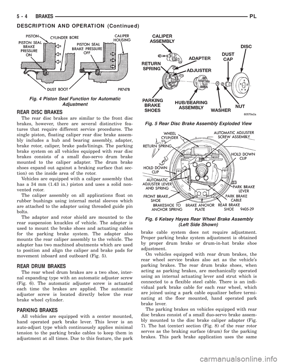
REAR DISC BRAKES
The rear disc brakes are similar to the front disc
brakes, however, there are several distinctive fea-
tures that require different service procedures. The
single piston, floating caliper rear disc brake assem-
bly includes a hub and bearing assembly, adapter,
brake rotor, caliper, brake pads/linings. The parking
brake system on all vehicles equipped with rear disc
brakes consists of a small duo-servo drum brake
mounted to the caliper adapter. The drum brake
shoes expand out against a braking surface (hat sec-
tion) on the inside area of the rotor.
Vehicles are equipped with a caliper assembly that
has a 34 mm (1.43 in.) piston and uses a solid non-
vented rotor.
The caliper assembly on all applications float on
rubber bushings using internal metal sleeves which
are attached to the adapter using threaded guide pin
bolts.
The adapter and rotor shield are mounted to the
rear suspension knuckles of vehicle. The adapter is
used to mount the brake shoes and actuating cables
for the parking brake system. The adapter also
mounts the rear caliper assembly to the vehicle. The
adapter has two machined abutments which are used
to position and align the caliper and brake pads for
movement inboard and outboard (Fig. 5).
REAR DRUM BRAKES
The rear wheel drum brakes are a two shoe, inter-
nal expanding type with an automatic adjuster screw
(Fig. 6). The automatic adjuster screw is actuated
each time the brakes are applied. The automatic
adjuster screw is located directly below the rear
brake wheel cylinder.
PARKING BRAKES
All vehicles are equipped with a center mounted,
hand operated park brake lever. This lever is an
auto-adjust type which continuously applies minimal
tension to the parking brake cables to keep them in
adjustment at all times. Due to this feature, the parkbrake cable system does not require adjustment.
Proper parking brake system adjustment is obtained
by proper drum brake or drum-in-hat brake shoe
adjustment.
On vehicles equipped with rear drum brakes, the
rear wheel service brakes also act as the vehicle's
parking brakes. The rear drum brake shoes, when
acting as parking brakes, are mechanically operated
using an internal actuating lever and strut which is
connected to a flexible steel cable. There is an indi-
vidual park brake cable for each rear wheel, which
are joined using a park cable equalizer before termi-
nating at the floor mounted, hand operated park
brake lever.
The parking brakes on vehicles equipped with rear
disc brakes consist of a small duo-servo brake assem-
bly mounted to the disc brake caliper adapter (Fig.
7). The hat (center) section (Fig. 8) of the rear rotor
serves as the braking surface (drum) for the parking
brakes. This park brake application uses the same
Fig. 4 Piston Seal Function for Automatic
Adjustment
Fig. 5 Rear Disc Brake Assembly Exploded View
Fig. 6 Kelsey Hayes Rear Wheel Brake Assembly
(Left Side Shown)
5 - 4 BRAKESPL
DESCRIPTION AND OPERATION (Continued)
Page 103 of 1200
(5) Remove master cylinder from vise.
NOTE: Note: It is not necessary to bleed the entire
hydraulic system after replacing the master cylin-
der. But the master cylinder must have been bled
and filled upon installation.
BRAKE ROTOR MACHINING
BRAKE ROTOR MACHINING PROCEDURES
Any servicing of the rotor requires extreme care to
maintain the rotor to within service tolerances to
ensure proper brake action.
If the rotor surface is deeply scored or warped, or
there is a complaint of brake roughness or pulsation,
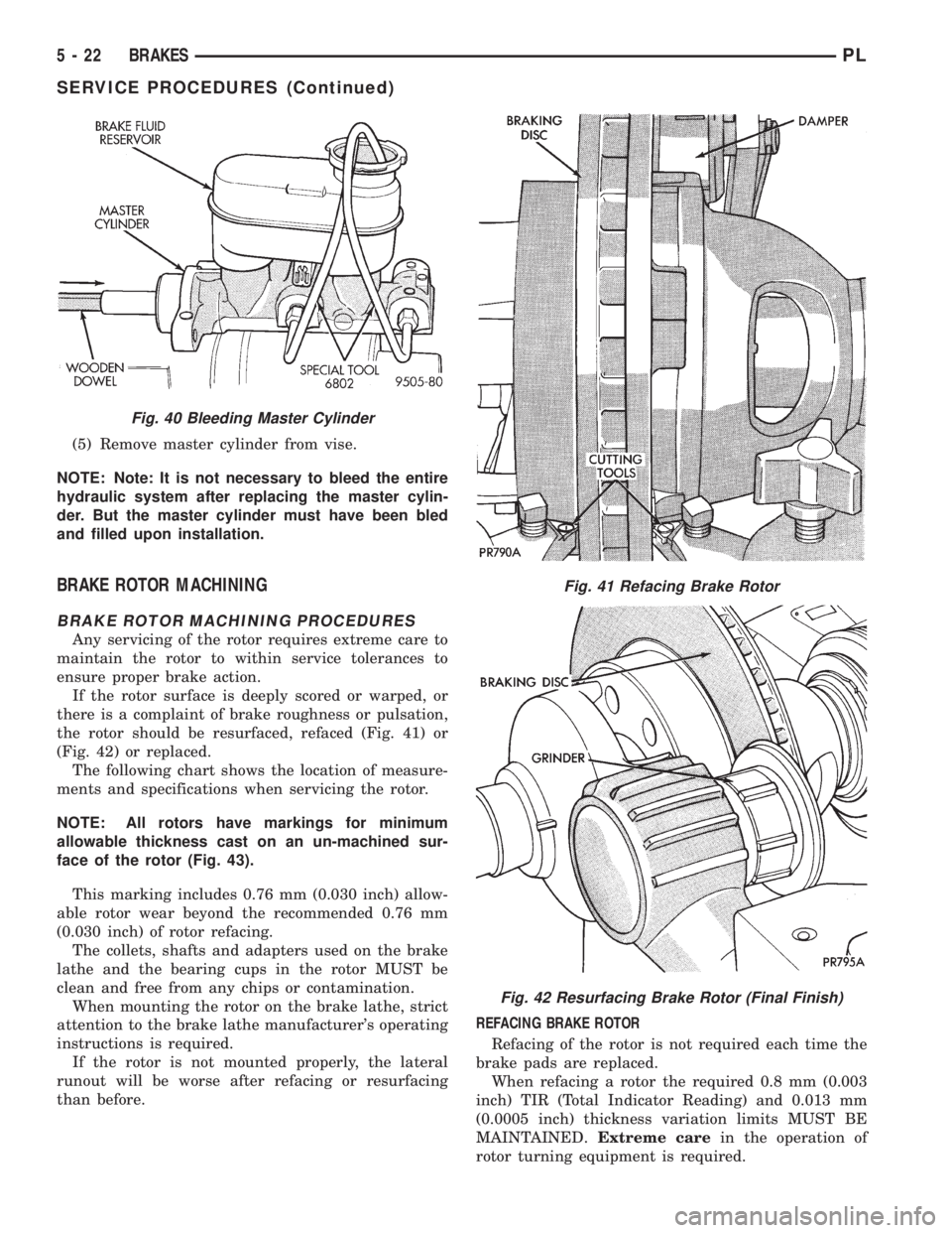
the rotor should be resurfaced, refaced (Fig. 41) or
(Fig. 42) or replaced.
The following chart shows the location of measure-
ments and specifications when servicing the rotor.
NOTE: All rotors have markings for minimum
allowable thickness cast on an un-machined sur-
face of the rotor (Fig. 43).
This marking includes 0.76 mm (0.030 inch) allow-
able rotor wear beyond the recommended 0.76 mm
(0.030 inch) of rotor refacing.
The collets, shafts and adapters used on the brake
lathe and the bearing cups in the rotor MUST be
clean and free from any chips or contamination.
When mounting the rotor on the brake lathe, strict
attention to the brake lathe manufacturer's operating
instructions is required.
If the rotor is not mounted properly, the lateral
runout will be worse after refacing or resurfacing
than before.REFACING BRAKE ROTOR
Refacing of the rotor is not required each time the
brake pads are replaced.
When refacing a rotor the required 0.8 mm (0.003
inch) TIR (Total Indicator Reading) and 0.013 mm
(0.0005 inch) thickness variation limits MUST BE
MAINTAINED.Extreme carein the operation of
rotor turning equipment is required.
Fig. 40 Bleeding Master Cylinder
Fig. 41 Refacing Brake Rotor
Fig. 42 Resurfacing Brake Rotor (Final Finish)
5 - 22 BRAKESPL
SERVICE PROCEDURES (Continued)
Page 108 of 1200
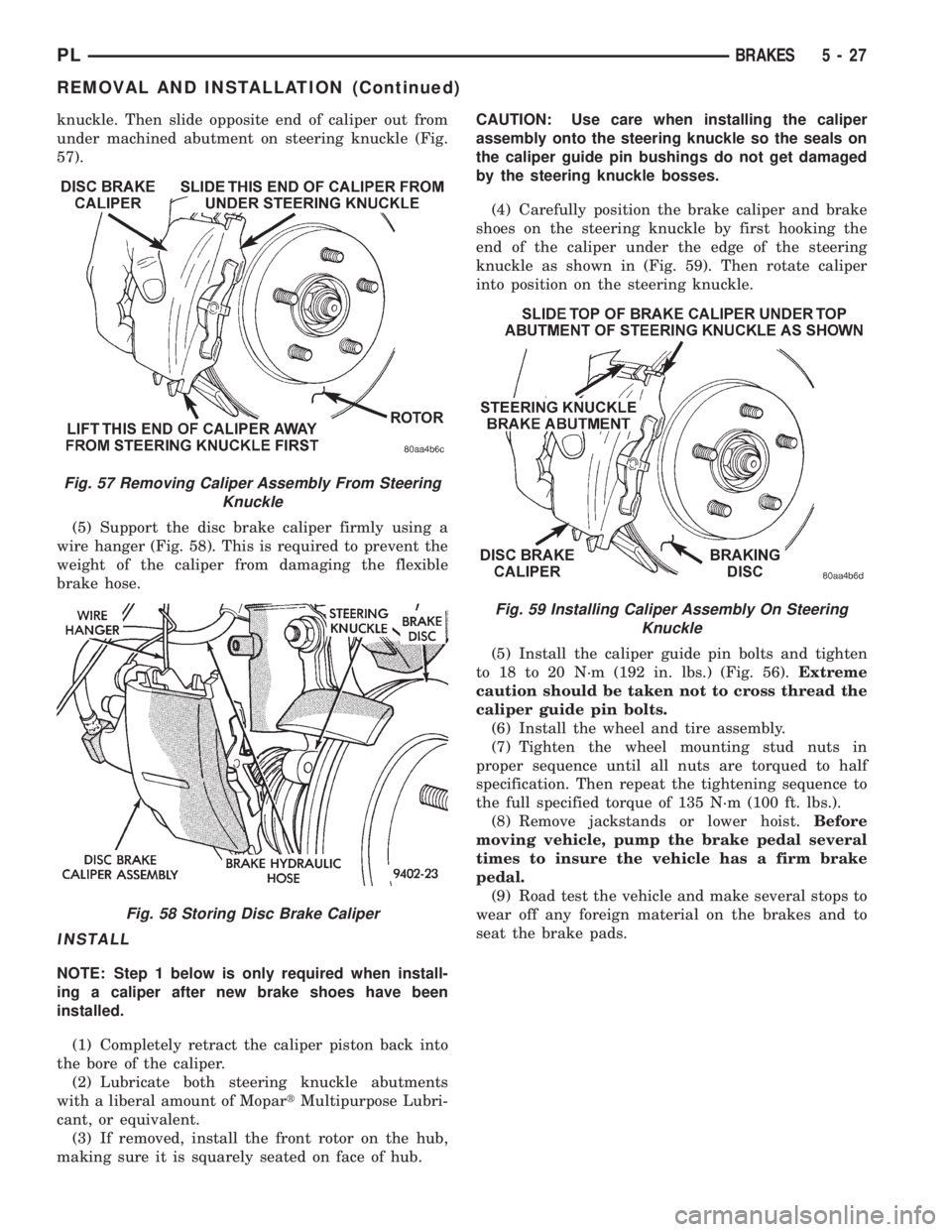
knuckle. Then slide opposite end of caliper out from
under machined abutment on steering knuckle (Fig.
57).
(5) Support the disc brake caliper firmly using a
wire hanger (Fig. 58). This is required to prevent the
weight of the caliper from damaging the flexible
brake hose.
INSTALL
NOTE: Step 1 below is only required when install-
ing a caliper after new brake shoes have been
installed.
(1) Completely retract the caliper piston back into
the bore of the caliper.
(2) Lubricate both steering knuckle abutments
with a liberal amount of MopartMultipurpose Lubri-
cant, or equivalent.
(3) If removed, install the front rotor on the hub,
making sure it is squarely seated on face of hub.CAUTION: Use care when installing the caliper
assembly onto the steering knuckle so the seals on
the caliper guide pin bushings do not get damaged
by the steering knuckle bosses.
(4) Carefully position the brake caliper and brake
shoes on the steering knuckle by first hooking the
end of the caliper under the edge of the steering
knuckle as shown in (Fig. 59). Then rotate caliper
into position on the steering knuckle.
(5) Install the caliper guide pin bolts and tighten
to 18 to 20 N´m (192 in. lbs.) (Fig. 56).Extreme
caution should be taken not to cross thread the
caliper guide pin bolts.
(6) Install the wheel and tire assembly.
(7) Tighten the wheel mounting stud nuts in
proper sequence until all nuts are torqued to half
specification. Then repeat the tightening sequence to
the full specified torque of 135 N´m (100 ft. lbs.).
(8) Remove jackstands or lower hoist.Before
moving vehicle, pump the brake pedal several
times to insure the vehicle has a firm brake
pedal.
(9) Road test the vehicle and make several stops to
wear off any foreign material on the brakes and to
seat the brake pads.
Fig. 57 Removing Caliper Assembly From Steering
Knuckle
Fig. 58 Storing Disc Brake Caliper
Fig. 59 Installing Caliper Assembly On Steering
Knuckle
PLBRAKES 5 - 27
REMOVAL AND INSTALLATION (Continued)
Page 111 of 1200
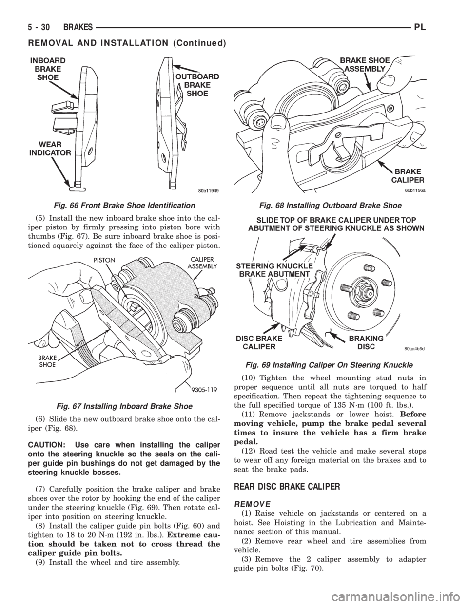
(5) Install the new inboard brake shoe into the cal-
iper piston by firmly pressing into piston bore with
thumbs (Fig. 67). Be sure inboard brake shoe is posi-
tioned squarely against the face of the caliper piston.
(6) Slide the new outboard brake shoe onto the cal-
iper (Fig. 68).
CAUTION: Use care when installing the caliper
onto the steering knuckle so the seals on the cali-
per guide pin bushings do not get damaged by the
steering knuckle bosses.
(7) Carefully position the brake caliper and brake
shoes over the rotor by hooking the end of the caliper
under the steering knuckle (Fig. 69). Then rotate cal-
iper into position on steering knuckle.
(8) Install the caliper guide pin bolts (Fig. 60) and
tighten to 18 to 20 N´m (192 in. lbs.).Extreme cau-
tion should be taken not to cross thread the
caliper guide pin bolts.
(9) Install the wheel and tire assembly.(10) Tighten the wheel mounting stud nuts in
proper sequence until all nuts are torqued to half
specification. Then repeat the tightening sequence to
the full specified torque of 135 N´m (100 ft. lbs.).
(11) Remove jackstands or lower hoist.Before
moving vehicle, pump the brake pedal several
times to insure the vehicle has a firm brake
pedal.
(12) Road test the vehicle and make several stops
to wear off any foreign material on the brakes and to
seat the brake pads.
REAR DISC BRAKE CALIPER
REMOVE
(1) Raise vehicle on jackstands or centered on a
hoist. See Hoisting in the Lubrication and Mainte-
nance section of this manual.
(2) Remove rear wheel and tire assemblies from
vehicle.
(3) Remove the 2 caliper assembly to adapter
guide pin bolts (Fig. 70).
Fig. 66 Front Brake Shoe Identification
Fig. 67 Installing Inboard Brake Shoe
Fig. 68 Installing Outboard Brake Shoe
Fig. 69 Installing Caliper On Steering Knuckle
5 - 30 BRAKESPL
REMOVAL AND INSTALLATION (Continued)
Page 113 of 1200
(4) Carefully lower caliper and brake shoe assem-
blies over braking disc (rotor) reversing the required
removal procedure (Fig. 71). Make sure that the cal-
iper guide pin bolts, bushings and sleeves are clear of
the adapter bosses.
CAUTION: Extreme caution should be taken not to
cross thread the caliper guide pin bolts when they
are installed.
(5) Install caliper assembly guide pin bolts into
adapter and tighten (Fig. 70). Then torque both guide
pin bolts to 22 N´m (192 in. lbs.).
(6) Install the wheel and tire assembly.
(7) Tighten the wheel mounting stud nuts in
proper sequence until all nuts are torqued to half
specification. Then repeat the tightening sequence to
the full specified torque of 135 N´m (100 ft. lbs.).
(8) Remove jackstands or lower hoist.Before
moving vehicle, pump the brake pedal several
times to insure the vehicle has a firm brake
pedal.
(9) Road test the vehicle and make several stops to
wear off any foreign material on the brakes and to
seat the brake pads.
REAR DISC BRAKE SHOES
WARNING: ALTHOUGH FACTORY INSTALLED
BRAKELININGS ARE MADE FROM ASBESTOS
FREE MATERIALS, SOME AFTER MARKET BRAKE-
LINING MAY CONTAIN ASBESTOS. THIS SHOULD
BE TAKEN INTO ACCOUNT WHEN SERVICING A
VEHICLE'S BRAKE SYSTEM, WHEN AFTERMARKET
BRAKELININGS MAY HAVE BEEN INSTALLED ON
THE VEHICLE. ALWAYS WEAR A RESPIRATOR
WHEN CLEANING BRAKE COMPONENTS AS
ASBESTOS CAN CAUSE SERIOUS BODILY HARM
SUCH AS ASBESTOSIS AND OR CANCER. NEVER
CLEAN BRAKE COMPONENTS BY USING COM-
PRESSED AIR, USE ONLY A VACUUM CLEANER
SPECIFICALLY DESIGNED FOR THE REMOVAL OF
BRAKE DUST. IF A VACUUM CLEANER IS NOT
AVAILABLE, CLEAN BRAKE PARTS USING ONLY
WATER DAMPENED SHOP TOWELS. DO NOT CRE-
ATE BRAKELINING DUST BY SANDING BRAKE LIN-
INGS WHEN SERVICING A VEHICLE. DISPOSE OF
ALL DUST AND DIRT SUSPECTED OF CONTAINING
ASBESTOS FIBERS USING ONLY SEALED AIR-
TIGHT BAGS OR CONTAINERS. FOLLOW ALL REC-
OMMENDED SAFETY PRACTICES PRESCRIBED BY
THE OCCUPATIONAL SAFETY AND HEALTH ADMIN-
ISTRATION (OSHA) AND THE ENVIRONMENTAL
PROTECTION AGENCY (EPA), FOR HANDLING AND
DISPOSAL OF PRODUCTS CONTAINING ASBES-
TOS.During service procedures, grease or any other for-
eign material must be kept off caliper assembly, sur-
faces of braking rotor and external surfaces of hub.
Handling of the braking rotor and caliper should
be done in such a way as to avoid deformation of the
rotor and scratching or nicking of the brake linings.
If inspection reveals that the square sectioned cal-
iper piston seal is worn or damaged, it should be
replaced immediately.
During removal and installation of a wheel and
tire assembly, use care not to strike the caliper.
NOTE: Before vehicle is moved after any brake
service work, pump the brake pedal several times
to insure the vehicle has a firm brake pedal.
NOTE: Starting with the 1998 model year, different
lining material is used on the rear disc brake shoes.
Vehicles equipped with optional 4 wheel disc
brakes use a new lining material on the rear disc
brake shoes than prior model year vehicles
equipped with this brake system. When new brake
shoes are installed, be sure brake shoes for the
correct model year and type of brake system the
vehicle is equipped with are used.REMOVE
(1) Raise vehicle on jackstands or centered on a
hoist. See Hoisting in the Lubrication and Mainte-
nance section of this manual.
(2) Remove rear wheel and tire assemblies from
vehicle.
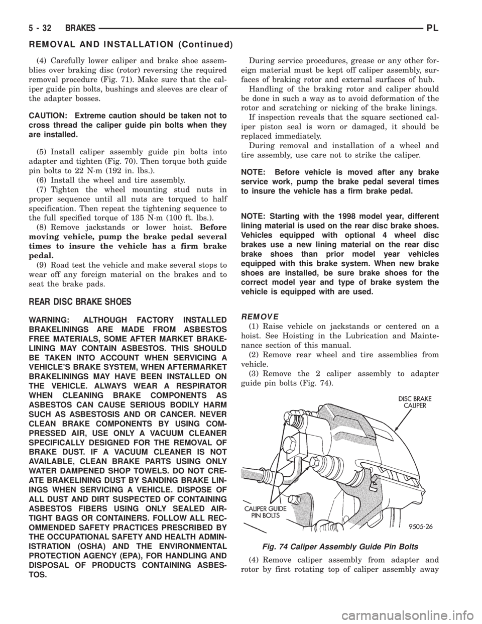
(3) Remove the 2 caliper assembly to adapter
guide pin bolts (Fig. 74).
(4) Remove caliper assembly from adapter and
rotor by first rotating top of caliper assembly away
Fig. 74 Caliper Assembly Guide Pin Bolts
5 - 32 BRAKESPL
REMOVAL AND INSTALLATION (Continued)