instrument panel DODGE NEON 1999 Service Repair Manual
[x] Cancel search | Manufacturer: DODGE, Model Year: 1999, Model line: NEON, Model: DODGE NEON 1999Pages: 1200, PDF Size: 35.29 MB
Page 88 of 1200
boosters differ at the interface to the master cylinder.
If the power brake booster requires replacement be
sure it is replaced with the correct part.
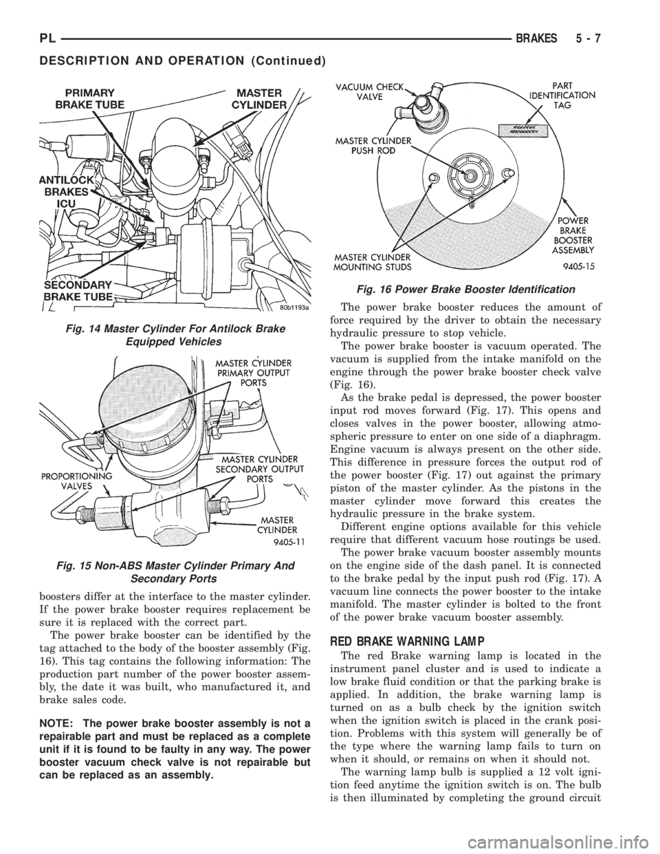
The power brake booster can be identified by the
tag attached to the body of the booster assembly (Fig.
16). This tag contains the following information: The
production part number of the power booster assem-
bly, the date it was built, who manufactured it, and
brake sales code.
NOTE: The power brake booster assembly is not a
repairable part and must be replaced as a complete
unit if it is found to be faulty in any way. The power
booster vacuum check valve is not repairable but
can be replaced as an assembly.The power brake booster reduces the amount of
force required by the driver to obtain the necessary
hydraulic pressure to stop vehicle.
The power brake booster is vacuum operated. The
vacuum is supplied from the intake manifold on the
engine through the power brake booster check valve
(Fig. 16).
As the brake pedal is depressed, the power booster
input rod moves forward (Fig. 17). This opens and
closes valves in the power booster, allowing atmo-
spheric pressure to enter on one side of a diaphragm.
Engine vacuum is always present on the other side.
This difference in pressure forces the output rod of
the power booster (Fig. 17) out against the primary
piston of the master cylinder. As the pistons in the
master cylinder move forward this creates the
hydraulic pressure in the brake system.
Different engine options available for this vehicle
require that different vacuum hose routings be used.
The power brake vacuum booster assembly mounts
on the engine side of the dash panel. It is connected
to the brake pedal by the input push rod (Fig. 17). A
vacuum line connects the power booster to the intake
manifold. The master cylinder is bolted to the front
of the power brake vacuum booster assembly.
RED BRAKE WARNING LAMP
The red Brake warning lamp is located in the
instrument panel cluster and is used to indicate a
low brake fluid condition or that the parking brake is
applied. In addition, the brake warning lamp is
turned on as a bulb check by the ignition switch
when the ignition switch is placed in the crank posi-
tion. Problems with this system will generally be of
the type where the warning lamp fails to turn on
when it should, or remains on when it should not.
The warning lamp bulb is supplied a 12 volt igni-
tion feed anytime the ignition switch is on. The bulb
is then illuminated by completing the ground circuit
Fig. 14 Master Cylinder For Antilock Brake
Equipped Vehicles
Fig. 15 Non-ABS Master Cylinder Primary And
Secondary Ports
Fig. 16 Power Brake Booster Identification
PLBRAKES 5 - 7
DESCRIPTION AND OPERATION (Continued)
Page 126 of 1200
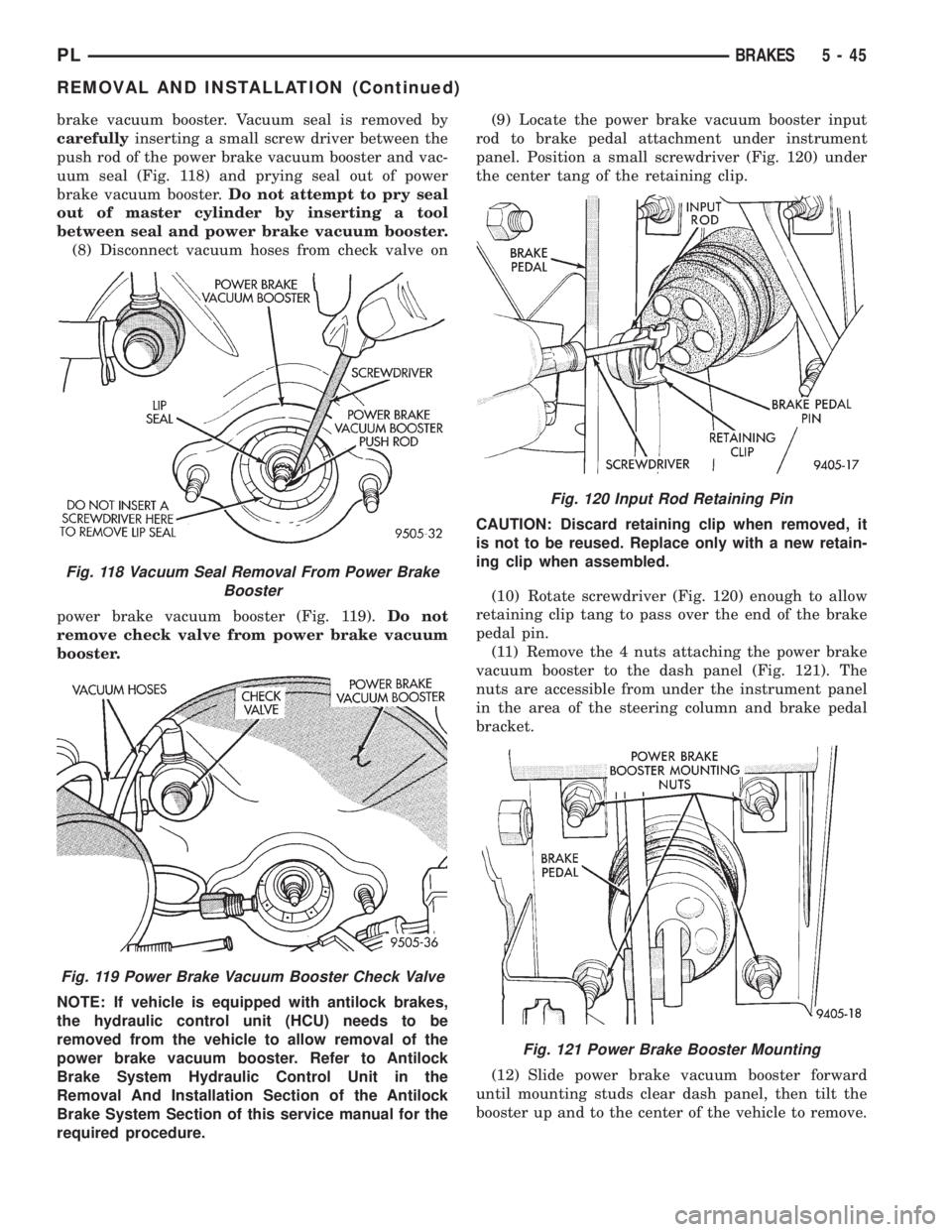
brake vacuum booster. Vacuum seal is removed by
carefullyinserting a small screw driver between the
push rod of the power brake vacuum booster and vac-
uum seal (Fig. 118) and prying seal out of power
brake vacuum booster.Do not attempt to pry seal
out of master cylinder by inserting a tool
between seal and power brake vacuum booster.
(8) Disconnect vacuum hoses from check valve on
power brake vacuum booster (Fig. 119).Do not
remove check valve from power brake vacuum
booster.
NOTE: If vehicle is equipped with antilock brakes,
the hydraulic control unit (HCU) needs to be
removed from the vehicle to allow removal of the
power brake vacuum booster. Refer to Antilock
Brake System Hydraulic Control Unit in the
Removal And Installation Section of the Antilock
Brake System Section of this service manual for the
required procedure.(9) Locate the power brake vacuum booster input
rod to brake pedal attachment under instrument
panel. Position a small screwdriver (Fig. 120) under
the center tang of the retaining clip.
CAUTION: Discard retaining clip when removed, it
is not to be reused. Replace only with a new retain-
ing clip when assembled.
(10) Rotate screwdriver (Fig. 120) enough to allow
retaining clip tang to pass over the end of the brake
pedal pin.
(11) Remove the 4 nuts attaching the power brake
vacuum booster to the dash panel (Fig. 121). The
nuts are accessible from under the instrument panel
in the area of the steering column and brake pedal
bracket.
(12) Slide power brake vacuum booster forward
until mounting studs clear dash panel, then tilt the
booster up and to the center of the vehicle to remove.
Fig. 118 Vacuum Seal Removal From Power Brake
Booster
Fig. 119 Power Brake Vacuum Booster Check Valve
Fig. 120 Input Rod Retaining Pin
Fig. 121 Power Brake Booster Mounting
PLBRAKES 5 - 45
REMOVAL AND INSTALLATION (Continued)
Page 162 of 1200
For the specific procedure covering the inspection
of the brake fluid level and adding brake fluid to the
reservoir, refer to the Service Adjustments Section in
this group of the service manual.
BLEEDING TEVES MARK 20 HYDRAULIC SYSTEM
The hydraulic system for the base brakes must be
bled anytime air enters the hydraulic system. Air can
enter the hydraulic system for the base brakes due to
the disconnection of brake lines, hoses or any other
hydraulically operated component of the base brake
system. The ABS system, particularly the ICU,
should only be bled when the ICU is replaced or it is
removed from the vehicle. The ICU must also always
be bled if for any reason it is suspected that the ICU
has ingested air. Under most circumstances that
require the bleeding of the brakes hydraulic system,
only the base brake hydraulic system needs to be
bled.
It is important to note that excessive air in the
brake system will cause a soft or spongy feeling
brake pedal.
During the brake bleeding procedure, be sure the
brake fluid level remains close to the FULL level in
the master cylinder fluid reservoir. Check the fluid
level periodically during the bleeding procedure and
add DOT 3 brake fluid as required.
The ITT Teves Mark 20 ABS must be bled as two
independent braking systems. The non ABS portion
of the brake system is to be bled the same as any
non ABS system. Refer to the Service Adjustments
section in this manual for the proper bleeding proce-
dure to be used. This brake system can be either
pressure bled or manually bled.
The ABS portion of the brake system MUST be
bled separately. This bleeding procedure requires the
use of the DRB Diagnostic Tester and the bleeding
sequence procedure outlined below.
ABS BLEEDING PROCEDURE
When bleeding the ABS system, the following
bleeding sequenceMUSTbe followed to insure com-
plete and adequate bleeding. The ABS system can be
bled using a manual bleeding procedure or standard
pressure bleeding equipment.
If the brake system is to be bled using pressurized
bleeding equipment, refer to Bleeding Brake System
in the Service Adjustments section at the beginning
of this group for proper equipment usage and proce-
dures.
(1) Assemble and install all brake system compo-
nents on the vehicle making sure all hydraulic fluid
lines are installed and properly torqued.
(2) Connect the DRB Diagnostics Tester to the
diagnostics connector. The Teves Mark 20 ABS diag-
nostic connector is located under the instrument
panel to the left of the steering column cover.(3) Using the DRB, check to make sure the CAB
does not have any fault codes stored. If it does,
remove them using the DRB.
WARNING: WHEN BLEEDING THE BRAKE SYS-
TEM WEAR SAFETY GLASSES. A CLEAR BLEED
TUBE MUST BE ATTACHED TO THE BLEEDER
SCREWS AND SUBMERGED IN A CLEAR CON-
TAINER FILLED PART WAY WITH CLEAN BRAKE
FLUID. DIRECT THE FLOW OF BRAKE FLUID AWAY
FROM THE PAINTED SURFACES OF THE VEHICLE.
BRAKE FLUID AT HIGH PRESSURE MAY COME
OUT OF THE BLEEDER SCREWS WHEN OPENED.
(4) Bleed the base brake system using the stan-
dard pressure or manual bleeding procedure as out-
lined in the Service Adjustments section of this
service manual.
(5) Using the DRB, go to the9Bleed ABS9routine.
Apply the brake pedal firmly and initiate the9Bleed
ABS9cycle one time. Release the brake pedal.
(6) Bleed the base brake system again, as in step
Step 4 above.
(7) Repeat steps Step 5 and Step 6 above until
brake fluid flows clear and is free of any air bubbles.
Check brake fluid level in reservoir periodically to
prevent reservoir from running low on brake fluid.
(8) Test drive the vehicle to be sure brakes are
operating correctly and that the brake pedal does not
feel spongy.
REMOVAL AND INSTALLATION
ABS GENERAL SERVICE PRECAUTIONS
CAUTION: Review this entire section prior to per-
forming any mechanical work on a vehicle equipped
with the ITT Tevis Mark 20 ABS brake system. This
section contains information on precautions per-
taining to potential component damage, vehicle
damage and personal injury which could result
when servicing an ABS equipped vehicle.
CAUTION: Only the recommended jacking or hoist-
ing positions for this vehicle are to be used when-
ever it is necessary to lift a vehicle. Failure to raise
a vehicle from the recommended locations could
result in lifting a vehicle by the hydraulic control
unit mounting bracket. Lifting a vehicle by the
hydraulic control unit mounting bracket will result
in damage to the mounting bracket and the hydrau-
lic control unit.
PLBRAKES 5 - 81
SERVICE PROCEDURES (Continued)
Page 173 of 1200
The clutch cable has a unique self-adjuster mecha-
nism built into the cable which compensates for
clutch disc wear. The cable requires no maintenance
or lubrication. There are no serviceable components
on the cable assembly.
The clutch pedal is connected to the cable through
a plastic spacer. The upper end of the clutch pedal
pivots in the pedal bracket on two nylon bushings
and a shaft. These bushings are greased at assembly
and do not require periodic lubrication.
CLUTCH DISC AND COVER APPLICATION
The 2.0 single overhead cam engine uses a 216 mm
(8.5 in.) clutch disc. The manual transaxle is avail-
able only with the 2.0 liter engine.
CLUTCH REPLACEMENT
The transaxle must be removed to service the
clutch disc, pressure plate, flywheel/drive plate,
and/or clutch release bearing and lever.
DESCRIPTION AND OPERATION
CLUTCH CABLE
The manual transaxle clutch release system has a
unique self-adjusting mechanism to compensate for
clutch disc wear. This adjuster mechanism is located
within the clutch cable assembly. The preload spring
maintains tension on the cable. This tension keeps
the clutch release bearing continuously loaded
against the fingers of the clutch cover assembly.
CLUTCH PEDAL POSITION SWITCH
The clutch pedal position switch functions as a
safety interlock device. It prevents possible engine
cranking with the clutch engaged.
The clutch pedal position switch is wired in series
between the starter relay coil and the ignition
switch.
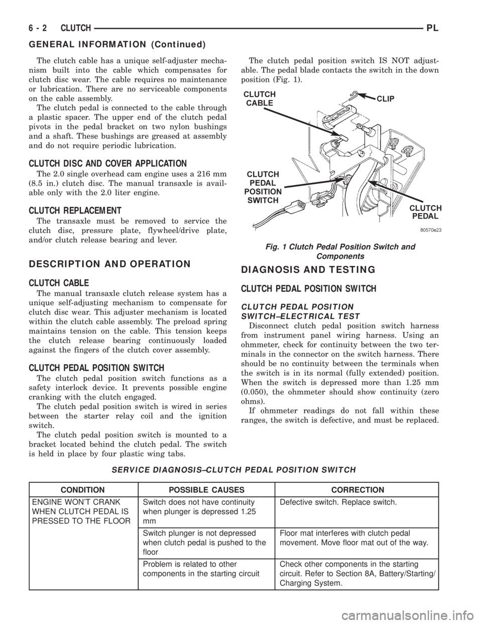
The clutch pedal position switch is mounted to a
bracket located behind the clutch pedal. The switch
is held in place by four plastic wing tabs.The clutch pedal position switch IS NOT adjust-
able. The pedal blade contacts the switch in the down
position (Fig. 1).
DIAGNOSIS AND TESTING
CLUTCH PEDAL POSITION SWITCH
CLUTCH PEDAL POSITION
SWITCH±ELECTRICAL TEST
Disconnect clutch pedal position switch harness
from instrument panel wiring harness. Using an
ohmmeter, check for continuity between the two ter-
minals in the connector on the switch harness. There
should be no continuity between the terminals when
the switch is in its normal (fully extended) position.
When the switch is depressed more than 1.25 mm
(0.050), the ohmmeter should show continuity (zero
ohms).
If ohmmeter readings do not fall within these
ranges, the switch is defective, and must be replaced.
SERVICE DIAGNOSIS±CLUTCH PEDAL POSITION SWITCH
CONDITION POSSIBLE CAUSES CORRECTION
ENGINE WON'T CRANK
WHEN CLUTCH PEDAL IS
PRESSED TO THE FLOORSwitch does not have continuity
when plunger is depressed 1.25
mmDefective switch. Replace switch.
Switch plunger is not depressed
when clutch pedal is pushed to the
floorFloor mat interferes with clutch pedal
movement. Move floor mat out of the way.
Problem is related to other
components in the starting circuitCheck other components in the starting
circuit. Refer to Section 8A, Battery/Starting/
Charging System.
Fig. 1 Clutch Pedal Position Switch and
Components
6 - 2 CLUTCHPL
GENERAL INFORMATION (Continued)
Page 211 of 1200
(9) Perform camshaft and crankshaft timing
relearn procedure as follows:
²Connect the DRB scan tool to the data link
(diagnostic) connector. This connector is located in
the passenger compartment; at the lower edge of
instrument panel; near the steering column.
²Turn the ignition switch on and access the ªmis-
cellaneousº screen.
²Select ªre-learn cam/crankº option and follow
directions on DRB screen.
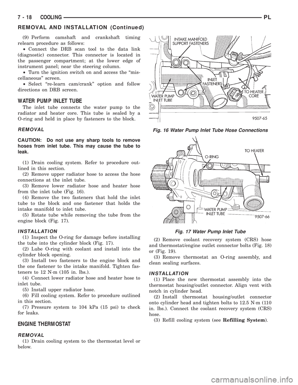
WATER PUMP INLET TUBE
The inlet tube connects the water pump to the
radiator and heater core. This tube is sealed by a
O-ring and held in place by fasteners to the block.
REMOVAL
CAUTION: Do not use any sharp tools to remove
hoses from inlet tube. This may cause the tube to
leak.
(1) Drain cooling system. Refer to procedure out-
lined in this section.
(2) Remove upper radiator hose to access the hose
connections at the inlet tube.
(3) Remove lower radiator hose and heater hose
from the inlet tube (Fig. 16).
(4) Remove the two fasteners that hold the inlet
tube to the block and one fastener that holds the
intake manifold to inlet tube.
(5) Rotate tube while removing the tube from the
engine block (Fig. 17).
INSTALLATION
(1) Inspect the O-ring for damage before installing
the tube into the cylinder block (Fig. 17).
(2) Lube O-ring with coolant and install into the
cylinder block opening.
(3) Install two fasteners to the engine block and
the one fastener to the intake manifold. Tighten fas-
teners to 12 N´m (105 in. lbs.).
(4) Connect lower radiator hose and heater hose to
inlet tube.
(5) Install upper radiator hose.
(6) Fill cooling system. Refer to procedure outlined
in this section.
(7) Pressure system to 104 kPa (15 psi) to check
for leaks.
ENGINE THERMOSTAT
REMOVAL
(1) Drain cooling system to the thermostat level or
below.(2) Remove coolant recovery system (CRS) hose
and thermostat/engine outlet connector bolts (Fig. 18)
or (Fig. 19).
(3) Remove thermostat an O-ring assembly, and
clean sealing surfaces.
INSTALLATION
(1) Place the new thermostat assembly into the
thermostat housing/outlet connector. Align vent with
notch in cylinder head.
(2) Install thermostat housing/outlet connector
onto cylinder head and tighten bolts to 12.5 N´m (110
in. lbs.). Connect the coolant recovery system (CRS)
hose.
(3) Refill cooling system (seeRefilling System).
Fig. 16 Water Pump Inlet Tube Hose Connections
Fig. 17 Water Pump Inlet Tube
7 - 18 COOLINGPL
REMOVAL AND INSTALLATION (Continued)
Page 231 of 1200
charge battery if necessary. Disconnect all testing
equipment and connect ASD relay or the Fuel Sole-
noid. Start the vehicle several times to assure the
problem has been corrected.
STARTING SYSTEM TEST
For circuit descriptions and diagrams, refer to
8W-21, Starting System in Group 8W, Wiring Dia-
grams.
WARNING: ON VEHICLES EQUIPPED WITH AIR-
BAGS, REFER TO GROUP 8M - PASSIVE
RESTRAINT SYSTEMS BEFORE ATTEMPTING
STEERING WHEEL, STEERING COLUMN, OR
INSTRUMENT PANEL COMPONENT DIAGNOSIS OR
SERVICE. FAILURE TO TAKE THE PROPER PRE-
CAUTIONS COULD RESULT IN ACCIDENTAL AIR-
BAG DEPLOYMENT AND POSSIBLE PERSONAL
INJURY.
INSPECTION
Before removing any unit from the starting system
for repair or diagnosis, perform the following inspec-
tions:
²Battery- Visually inspect the battery for indi-
cations of physical damage and loose or corroded
cable connections. Determine the state-of-charge and
cranking capacity of the battery. Charge or replace
the battery, if required. Refer to Group 8A, Battery
for more information.²Ignition Switch- Visually inspect the ignition
switch for indications of physical damage and loose
or corroded wire harness connections.
²Clutch Pedal Position Switch- Visually
inspect the clutch pedal position switch for indica-
tions of physical damage and loose or corroded wire
harness connections.
²Park/Neutral Position Switch- Visually
inspect the park/neutral position switch for indica-
tions of physical damage and loose or corroded wire
harness connections.
²Starter Relay- Visually inspect the starter
relay for indications of physical damage and loose or
corroded wire harness connections.
²Starter- Visually inspect the starter for indica-
tions of physical damage and loose or corroded wire
harness connections.
²Starter Solenoid- Visually inspect the starter
solenoid for indications of physical damage and loose
or corroded wire harness connections.
²Wiring- Visually inspect the wire harness for
damage. Repair or replace any faulty wiring, as
required.
8B - 4 STARTINGPL
DIAGNOSIS AND TESTING (Continued)
Page 236 of 1200
CHARGING SYSTEM
CONTENTS
page page
GENERAL INFORMATION
OVERVIEW............................. 1
DESCRIPTION AND OPERATION
BATTERY TEMPERATURE SENSOR.......... 2
CHARGING SYSTEM OPERATION........... 1
ELECTRONIC VOLTAGE REGULATOR......... 2
GENERATOR............................ 2
DIAGNOSIS AND TESTING
BATTERY TEMPERATURE SENSOR.......... 8
CHARGING SYSTEM RESISTANCE TESTS..... 5CHARGING SYSTEM...................... 2
CURRENT OUTPUT TEST.................. 8
ON-BOARD DIAGNOSTIC SYSTEM TEST..... 10
REMOVAL AND INSTALLATION
BATTERY TEMPERATURE SENSOR......... 11
GENERATOR........................... 10
SPECIFICATIONS
GENERATOR RATINGS................... 12
TORQUE.............................. 12
GENERAL INFORMATION
OVERVIEW
The battery, starting, and charging systems oper-
ate with one another, and must be tested as a com-
plete system. In order for the vehicle to start and
charge properly, all of the components involved in
these systems must perform within specifications.
Group 8A covers the battery, Group 8B covers the
starting system, and Group 8C covers the charging
system. Refer to Group 8W - Wiring Diagrams for
complete circuit descriptions and diagrams. We have
separated these systems to make it easier to locate
the information you are seeking within this Service
Manual. However, when attempting to diagnose any
of these systems, it is important that you keep their
interdependency in mind.
The diagnostic procedures used in these groups
include the most basic conventional diagnostic meth-
ods to the more sophisticated On-Board Diagnostics
(OBD) built into the Powertrain Control Module
(PCM). Use of an induction ammeter, volt/ohmmeter,
battery charger, carbon pile rheostat (load tester),
and 12-volt test lamp may be required.
All OBD-sensed systems are monitored by the
PCM. Each monitored circuit is assigned a Diagnos-
tic Trouble Code (DTC). The PCM will store a DTC in
electronic memory for any failure it detects. See the
On-Board Diagnostics Test in Group 8C - Charging
System for more information.
DESCRIPTION AND OPERATION
CHARGING SYSTEM OPERATION
The charging system consists of:
²Generator
²Electronic Voltage Regulator (EVR) circuitry
within the Powertrain Control Module (PCM)
²Ignition switch (refer to Group 8D, Ignition Sys-
tem for information)
²Battery (refer to Group 8A, Battery for informa-
tion)
²Battery temperature sensor
²Voltmeter (refer to Group 8E, Instrument Panel
and Gauges for information)
²Wiring harness and connections (refer to Group
8W, Wiring for information)
The charging system is turned on and off with the
ignition switch. When the ignition switch is turned to
the ON position, battery voltage is applied to the
generator rotor through one of the two field termi-
nals to produce a magnetic field. The generator is
driven by the engine through a serpentine belt and
pulley arrangement.
The amount of DC current produced by the gener-
ator is controlled by the EVR (field control) circuitry,
contained within the PCM. This circuitry is con-
nected in series with the second rotor field terminal
and ground.
PLCHARGING SYSTEM 8C - 1
Page 254 of 1200
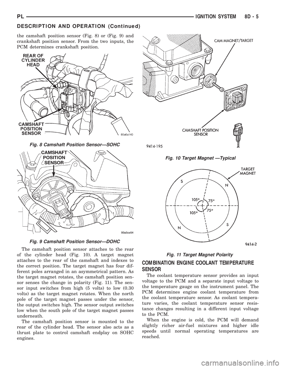
the camshaft position sensor (Fig. 8) or (Fig. 9) and
crankshaft position sensor. From the two inputs, the
PCM determines crankshaft position.
The camshaft position sensor attaches to the rear
of the cylinder head (Fig. 10). A target magnet
attaches to the rear of the camshaft and indexes to
the correct position. The target magnet has four dif-
ferent poles arranged in an asymmetrical pattern. As
the target magnet rotates, the camshaft position sen-
sor senses the change in polarity (Fig. 11). The sen-
sor input switches from high (5 volts) to low (0.30
volts) as the target magnet rotates. When the north
pole of the target magnet passes under the sensor,
the output switches high. The sensor output switches
low when the south pole of the target magnet passes
underneath.
The camshaft position sensor is mounted to the
rear of the cylinder head. The sensor also acts as a
thrust plate to control camshaft endplay on SOHC
engines.
COMBINATION ENGINE COOLANT TEMPERATURE
SENSOR
The coolant temperature sensor provides an input
voltage to the PCM and a separate input voltage to
the temperature gauge on the instrument panel. The
PCM determines engine coolant temperature from
the coolant temperature sensor. As coolant tempera-
ture varies, the coolant temperature sensor resis-
tance changes resulting in a different input voltage
to the PCM.
When the engine is cold, the PCM will demand
slightly richer air-fuel mixtures and higher idle
speeds until normal operating temperatures are
reached.
Fig. 8 Camshaft Position SensorÐSOHC
Fig. 9 Camshaft Position SensorÐDOHC
Fig. 10 Target Magnet ÐTypical
Fig. 11 Target Magnet Polarity
PLIGNITION SYSTEM 8D - 5
DESCRIPTION AND OPERATION (Continued)
Page 270 of 1200
INSTRUMENT PANEL AND SYSTEMS
CONTENTS
page page
GENERAL INFORMATION
INTRODUCTION......................... 1
DESCRIPTION AND OPERATION
DOME LAMP............................ 1
ELECTRONIC DIGITAL CLOCK.............. 1
INSTRUMENT CLUSTER................... 2
WARNING AND INDICATOR LAMPS......... 2
DIAGNOSIS AND TESTING
AIRBAG WARNING SYSTEM............... 2
BRAKE SYSTEM WARNING LAMP TEST...... 2
FOG LAMP SWITCH TEST................. 2
FUEL TANK SENDING UNIT TEST........... 3
HEADLAMP SWITCH TEST................. 3
HEATER A/C BLOWER SWITCH TEST........ 3
HEATER BLOWER SWITCH TEST............ 3
INDIVIDUAL GAUGE INOPERATIVE.......... 4
INSTRUMENT PANEL AND COMPONENTS.... 4
LOW OIL PRESSURE WARNING LAMP TEST . . 4
MULTIPLE GAUGE INOPERATIVE TEST....... 4
SEAT BELT REMINDER SYSTEM TEST....... 6
SENDING UNIT......................... 6
SERVICE ENGINE SOON INDICATOR......... 6
VEHICLE SPEED SENSOR TEST............. 6
REMOVAL AND INSTALLATION
ASH RECEIVER RETAINER AND LAMP....... 6
CENTER BEZEL.......................... 6
CIGAR LIGHTER RECEPTACLE.............. 6
CLUSTER LAMP......................... 7
CLUSTER PRINTED CIRCUIT BOARD........ 7CLUSTER.............................. 7
DOME LENS/LAMP....................... 8
FLOOR CONSOLE........................ 8
GAUGE................................ 8
GLOVE BOX DOOR/BIN................... 8
GLOVE BOX SWITCH/LAMP................ 9
HEADLAMP SWITCH..................... 9
HEATER A/C CONTROL BLOWER SWITCH . . . 10
HEATER A/C CONTROL LAMP............ 10
HEATER A/C CONTROL................... 9
HEATER CONTROL BLOWER SWITCH....... 10
IGNITION KEY LAMP.................... 10
INSTRUMENT PANEL.................... 10
LEFT TRIM PANEL...................... 10
ODOMETER............................ 10
RADIO................................ 12
REAR WINDOW DEFOGGER AND/OR FOG
LAMP SWITCH....................... 12
RIGHT TRIM PANEL..................... 12
SHIFTER KNOB......................... 13
STEERING COLUMN COVER LINER......... 13
STEERING COLUMN COVER.............. 13
STEERING COLUMN SHROUDS............ 13
TOP COVER AND CLUSTER BEZEL
REMOVAL........................... 14
TRANSMISSION RANGE INDICATOR LAMP . . 14
TRUNK LAMP/LENS..................... 14
VEHICLE SPEED SENSOR................ 14
GENERAL INFORMATION
INTRODUCTION
The purpose of the dash gauges and indicator
lamps is to keep the driver informed about the oper-
ating condition of the vehicle. If an abnormal condi-
tion occurs, the driver is informed by indicator lamp.
The driver can seek service before damage occurs.
Indicator lamps use ON/OFF switch functions for
operation, while gauges use a sending unit or sensor.
DESCRIPTION AND OPERATION
DOME LAMP
The Dome Lamp operates when a door is open or
when the headlamp switch is placed in courtesy posi-
tion.
ELECTRONIC DIGITAL CLOCK
The electronic digital clock is in the radio. The
clock and radio each use the display panel built into
the radio. A digital readout indicates the time in
hours and minutes whenever the ignition switch is in
the ON or ACC position.
PLINSTRUMENT PANEL AND SYSTEMS 8E - 1
Page 271 of 1200
When the ignition switch is in the OFF position, or
when the radio frequency is being displayed, time
keeping is accurately maintained.
The procedure for setting the clock varies slightly
with each radio. The correct procedure is described in
the individual radio operating instructions. Refer to
the Owner's Manual supplied with the vehicle.
INSTRUMENT CLUSTER
There are two conventional instrument cluster
assemblies available. The clusters electronically drive
the speedometer, odometer, and gauges (Fig. 1) and
(Fig. 2).
GAUGES
All gauges in the electronic clusters are the analog
type gauges. When the ignition switch is moved to
the OFF position, the cluster drives each gauge to its
lowest position.
WARNING AND INDICATOR LAMPS
The instrument cluster has warning lamps and
indicators for the following systems:
²Airbag
²Anti-lock Brakes (ABS) if equipped
²Brake warning
²Charging System
²Door Ajar
²High beam indicator
²Low oil pressure
²Malfunction indicator (service engine soon) lamp
²Right and left turn signals.
²Seat belt warning
DIAGNOSIS AND TESTING
AIRBAG WARNING SYSTEM
For testing of this system refer to Group 8M,
Restraint Systems.
BRAKE SYSTEM WARNING LAMP TEST
The brake warning lamp illuminates when the
parking brake is applied with ignition switch turned
to the ON position. The same lamp will also illumi-
nate if one of the two service brake systems fail the
when brake pedal is applied.
To test the system:
²As the ignition switch is turned to the start posi-
tion the lamp should light.
²Turn ignition switch to the ON position and
apply the parking brake. The lamp should light.
If lamp fails to light inspect for:
²A burned out lamp
²Loose, corroded or damaged socket
²A damaged circuit board
²A broken or disconnected wire at the switch
²Defective switch
To test the service brake warning system, refer to
Group 5, Brakes, Hydraulic System Control Valves.
FOG LAMP SWITCH TEST
(1) Remove the fog lamp switch. Refer to the Rear
Window Defogger and/or Fog Lamp Switch Removal.
(2) Using two jumper wires, connect Pin 2 and Pin
4 of the switch to battery voltage.
(3) Using a test lamp, connect the test lamp to Pin
3 as shown in (Fig. 3). Refer to (Fig. 4) for fog lamp
switch circuit.
(4) Push the fog lamp switch button. The test lamp
and the LED indicator on the front of the switch
should illuminate.
(5) If either the LED or the test lamp fails to illu-
minate, replace the switch.Fig. 1 Instrument Cluster Without Tachometer
Fig. 2 Instrument Cluster With Tachometer
Fig. 3 Fog Lamp Switch Test
8E - 2 INSTRUMENT PANEL AND SYSTEMSPL
DESCRIPTION AND OPERATION (Continued)